

The Essentials of Capacitor Impedance
Capacitor impedance is the total opposition a capacitor offers to alternating current (AC). You might think of sim
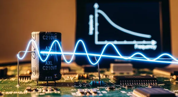
Capacitor impedance is the total opposition a capacitor offers to alternating current (AC). You might think of simple resistance, but impedance is dynamic and changes with frequency. For a capacitor, this opposition is called capacitive reactance, which you measure in Ohms (Ω).
A resistor directly opposes current. A capacitor, however, creates opposition by storing and releasing energy.
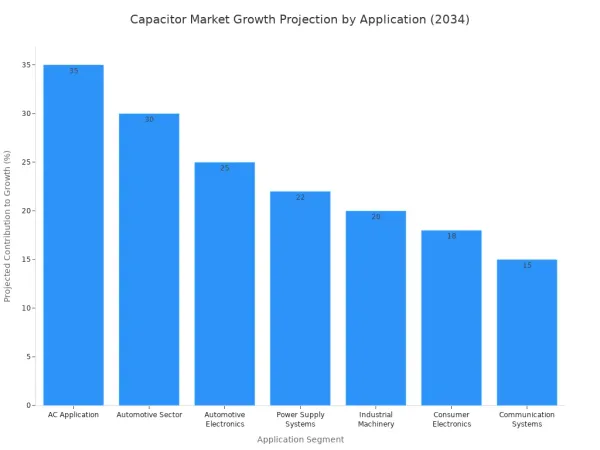
Understanding the impedance of capacitor is vital. The capacitor market is growing fast, with AC applications being a major segment.
| Application Segment | 2024 Market Share | Projected Contribution to Market Growth by 2034 |
|---|---|---|
| AC Application | 65.8% | 35% |
| Automotive Sector | 34.8% | 30% (of sector's market growth) |
This growth highlights the importance of the capacitor in various industries.
Key Takeaways
- Capacitor impedance is how much a capacitor resists alternating current (AC). This resistance changes with the signal's frequency.
- A capacitor acts like a gate. It blocks low-frequency signals and direct current (DC). It lets high-frequency signals pass through easily.
- You can use capacitors to filter signals, block DC, and smooth power. This makes them very useful in electronic devices.
- Real capacitors have small internal flaws. These flaws can affect how well they work, especially at high frequencies.
Calculating the Impedance of a Capacitor
To understand how a capacitor behaves in a circuit, you need to calculate its opposition to current. This calculation gives you the impedance of a capacitor. Let's break down the formulas you will use.
The Core Impedance Formula
The complete formula for a capacitor's impedance includes both its magnitude and phase shift. You express it this way:
The complex impedance
Zcof a capacitance is expressed with an imaginary componentjas:
Zc = 1 / (jωC)
This formula might look complex, so let's define each part:
- Zc is the impedance of the capacitor, measured in Ohms (Ω).
- j is the imaginary unit. It represents a 90-degree phase shift. In a capacitor, the current leads the voltage by 90 degrees. The
-jthat results from this formula mathematically shows you that the voltage lags the current. - ω (Omega) is the angular frequency of the AC signal, measured in radians per second. You find it by multiplying the frequency in Hertz by 2π (
ω = 2πf). - C is the capacitance of the capacitor, measured in Farads (F).
Finding Magnitude: Capacitive Reactance
In many real-world scenarios, you only need to know the magnitude of the impedance. This magnitude is called capacitive reactance (Xc). You can use a simpler formula to find it. This practical formula removes the imaginary unit j.
The formula for capacitive reactance is:
Xc = 1 / (2πfC)
Here, f is the frequency in Hertz (Hz). This formula is essential for circuit design. It shows that capacitive reactance is inversely proportional to both frequency and capacitance.
💡 Tip: A higher frequency or a larger capacitance will result in a lower capacitive reactance. The capacitor will oppose the current less.
Let's walk through an example. How do you find the capacitive reactance of a 10µF capacitor at a frequency of 60Hz?
- Identify your values:
- Capacitance (C) = 10µF, which you convert to
10 x 10⁻⁶Farads. - Frequency (f) = 60 Hz.
- Capacitance (C) = 10µF, which you convert to
- Use the reactance formula:
Xc = 1 / (2πfC)
- Substitute the values into the formula:
Xc = 1 / (2 × π × 60 Hz × 10 × 10⁻⁶ F)
- Calculate the result:
- The capacitive reactance (Xc) is approximately 265.25 Ω.
At 60Hz, this capacitor presents 265.25 Ohms of reactance to the current.
Ideal vs. Real Capacitor Impedance
The formulas above describe an ideal capacitor. However, a real-world capacitor is not perfect. It has small, unwanted internal characteristics called parasitic elements.
A real capacitor can be modeled as an ideal capacitor in series with:
- Equivalent Series Resistance (ESR): The internal resistance of the capacitor's materials.
- Equivalent Series Inductance (ESL): The internal inductance from the capacitor's physical construction.
The total impedance (Z) of a real capacitor combines all three elements: Z = ESR + j(ωESL – 1/ωC). At low frequencies, the capacitive reactance (1/ωC) dominates. But as the frequency gets very high, the inductive reactance (ωESL) starts to take over, and the impedance of the capacitor actually begins to rise again. The point where the capacitive reactance and inductive reactance cancel each other out is called the self-resonant frequency (SRF). At this frequency, the capacitor's impedance is at its absolute minimum and is equal to the ESR.
These parasitic elements are undesirable and can cause problems in circuits, especially at high frequencies. Their effects include:
- Increased energy dissipation as heat due to ESR.
- Reduced overall circuit efficiency.
- Generation of Electromagnetic Interference (EMI).
- Diminished capacitor responsiveness and performance.
For demanding, high-frequency designs, such as those in modern telecommunications and processing units, selecting a capacitor with low ESR and ESL is critical. This is where partnering with experts can make a significant difference. For instance, Nova Technology Company (HK) Limited, a HiSilicon-designated solutions partner, specializes in helping engineers choose optimal components to ensure circuit integrity and performance.
Frequency's Effect on a Capacitor
A capacitor's impedance is not a fixed value. It changes based on the frequency of the signal you apply. This dynamic behavior is what makes the capacitor such a versatile tool in electronics. You can think of a capacitor as a frequency-sensitive gate for current.
Behavior at Low Frequencies (Open Circuit)
At low frequencies, a capacitor strongly opposes the flow of current. The capacitive reactance is inversely proportional to frequency. As the frequency gets lower, the reactance of the capacitor gets higher.
For a direct current (DC) signal, the frequency is zero. This makes the capacitive reactance of the capacitor theoretically infinite. The capacitor charges up and then completely blocks any more current from flowing. It acts like an open switch or a break in the circuit.
This DC-blocking feature is extremely useful. You can use a capacitor to separate the AC and DC parts of a signal. This is common in applications like:
- Audio amplifiers
- RF communication systems
- Sensor interfaces
In these circuits, a coupling capacitor lets the desired AC signal pass between stages while stopping any unwanted DC voltage. This ensures different parts of your circuit do not interfere with each other's DC operating points.
Behavior at High Frequencies (Short Circuit)
On the other hand, a capacitor behaves very differently at high frequencies. As the signal frequency increases, the capacitive reactance of the capacitor drops significantly. The capacitor offers very little opposition to the current. At extremely high frequencies, the reactance becomes so low that the capacitor essentially acts like a short circuit or a simple piece of wire.
This behavior allows a capacitor to work as an effective noise filter. High-frequency noise is a common problem in electronic circuits, especially on power supply lines. By placing a capacitor between a power line and ground, you create an easy escape path for this noise.
- The capacitor provides a low-reactance path for high-frequency AC noise.
- The noise bypasses the sensitive components and goes directly to ground.
- The DC power, which the capacitor blocks, continues to the component as intended.
This is why you often see small bypass capacitors placed right next to the power pins of integrated circuits (ICs). A small value of capacitance is very effective at filtering high-frequency noise, keeping the power supply clean for the IC.
Practical Applications in Electronics
The dynamic impedance of a capacitor is more than just a number in a formula. It is a powerful property that you can use to control signals in electronic circuits. This frequency-dependent behavior allows a capacitor to act as a filter, a signal coupler, and a power smoother. Let's explore these essential roles.
Signal Filtering
You can use a capacitor to build circuits that separate signals based on their frequency. This process is called filtering. Because a capacitor has low impedance to high frequencies and high impedance to low frequencies, it acts as a frequency-sensitive gate.
A common example is a high-pass filter. This circuit allows high-frequency signals to pass through while blocking low-frequency ones.
To build a simple high-pass filter, you place the capacitor in series with the input signal. You then connect a resistor from the capacitor's output to the ground. The output signal is taken from across the resistor. High frequencies pass through the capacitor easily, while low frequencies are blocked.
You will find this principle at work in many audio devices, including:
- Speaker Crossovers: A capacitor directs high-frequency sounds to the tweeter.
- Equalizers: These use filters to boost or cut specific frequency ranges, letting you adjust bass and treble.
- Phono Preamps: A capacitor helps shape the signal coming from a vinyl record player.
- Notch Filters: You can design a filter to remove a specific unwanted frequency, like the 60 Hz hum from power lines that can sneak into an audio amplifier's output.
AC Coupling and DC Blocking
One of the most fundamental jobs for a capacitor is to separate AC signals from DC voltage. This is known as AC coupling or DC blocking. Many circuits, like audio amplifiers, have multiple stages. Each stage needs a specific DC voltage to work correctly, but you only want the AC signal (the music or voice) to pass between them.
A coupling capacitor makes this possible. It connects the output of one stage to the input of the next. Here is how it works:
- DC Signal Blocking: The capacitor charges up to the DC voltage of the first stage. Once charged, it acts like an open circuit to the DC, preventing it from affecting the next stage's bias.
- AC Signal Passage: The AC signal changes rapidly. The capacitor does not have enough time to fully charge or discharge in response to these quick changes. This allows the AC signal to pass through the capacitor with very little opposition.
This mechanism ensures each amplifier stage maintains its own DC operating point while the AC signal moves cleanly through the circuit.
💡 Choosing the Right Capacitor: Selecting the right coupling capacitor is critical. You must calculate the cutoff frequency using the capacitor value and the input impedance of the next stage. A common goal for audio is a cutoff frequency around 2 Hz to ensure all audible frequencies (20 Hz and up) pass through. Typical values are often 10 nF or 100 nF.
Choosing a capacitor with too low a capacitance can cause problems. It will form a high-pass filter with a higher cutoff frequency, which can reduce the low-frequency gain and make your audio sound thin. In some cases, it can even introduce nonlinear distortion. For critical designs where signal integrity is paramount, working with specialists who understand component selection is key. For example, a solutions partner like Nova Technology Company (HK) Limited, which is designated by HiSilicon, helps engineers select optimal components to avoid such issues.
Power Supply Smoothing
Electronic devices need a smooth, stable DC voltage to operate correctly. The power from a wall outlet is AC, so it must first be converted to DC using a circuit called a rectifier. However, the output of a rectifier is not perfectly flat; it has bumps and dips called "ripple." A smoothing capacitor, also known as a filter capacitor, is used to fix this.
The capacitor acts like a small, temporary energy reservoir.
- Charging: As the rectified voltage rises to its peak, the capacitor charges up, storing energy.
- Discharging: When the rectified voltage starts to fall, the capacitor discharges. It releases its stored energy, supplying current to the load and filling in the voltage dip.
- Recharging: On the next voltage peak, the capacitor recharges, and the cycle repeats.
This rapid charging and discharging action smooths out the ripple, turning the bumpy DC into a much more stable voltage. The higher the capacitance value of the capacitor, the more energy it can store and the smaller the final ripple voltage will be.
Because they need to store a large amount of charge, large electrolytic capacitors are commonly used for this purpose. Their high capacitance density makes them perfect for filtering out ripple and ensuring the stable operation of both linear and switch-mode power supplies.
The impedance of a capacitor is its frequency-dependent opposition to AC. You can think of a capacitor as a gate. Its high capacitive reactance blocks low frequencies, while its low reactance passes high ones. A capacitor with a higher capacitance has lower reactance. This inverse relationship is why a capacitor is essential for:
- Filtering: A capacitor removes noise.
- Coupling: A capacitor blocks DC.
- Smoothing: A capacitor stabilizes power.
Understanding the impedance of a capacitor and its capacitive reactance is fundamental. The reactance of a capacitor with a specific capacitance makes this capacitor a versatile tool.
FAQ
What is the difference between resistance and impedance?
You can think of resistance as a constant opposition to all current. Impedance is different. It is the total opposition to AC current and changes with frequency. A capacitor has impedance, not simple resistance.
Why does a capacitor block DC?
A direct current (DC) signal has zero frequency. This makes the impedance of a capacitor theoretically infinite. The capacitor charges up and then stops any more current from flowing. It acts like an open switch in the circuit.
Does a bigger capacitor always have lower impedance?
Yes, for a given frequency. The formula Xc = 1 / (2πfC) shows this relationship. A capacitor with a larger capacitance (C) will have a lower impedance. This means it allows more AC current to pass through it.
What happens at a capacitor's self-resonant frequency?
At its self-resonant frequency (SRF), a real-world capacitor has its lowest possible impedance. At this specific point, the capacitor's internal inductance cancels out its capacitance. The only opposition left is its internal resistance (ESR).


