The hidden role of the time constant of RC circuit
The time constant of RC circuit is the fundamental clockwork inside electronics. It governs how quickly a circuit

The time constant of RC circuit is the fundamental clockwork inside electronics. It governs how quickly a circuit responds to change. This single value is the key to understanding many critical functions. It helps with signal filtering, timing events, and creating clean signals in electronics.
Imagine filling a leaky bucket. Resistance is like the narrow pipe controlling water inflow. Capacitance is the size of the bucket. A larger pipe (less resistance) or a smaller bucket (less capacitance) means it fills faster. This relationship is the core of the RC time constant.
Key Takeaways
- The RC time constant (τ = R * C) shows how fast a circuit reacts to changes. It is key for understanding how electronic parts work.
- RC circuits can smooth signals by acting as filters. Low-pass filters remove noise, and high-pass filters block unwanted DC voltage.
- RC circuits create timing for electronics. They make clock pulses for digital devices and cause delays for system resets.
- RC circuits help digital systems work better. They stop switches from bouncing and manage how fast signals change in high-speed circuits.
- The 5τ rule means a capacitor is fully charged or discharged after five time constants. This rule helps engineers design reliable circuits.
Defining the time constant of RC circuit
The time constant, represented by the Greek letter tau (τ), is the product of resistance (R) and capacitance (C). This value, calculated as τ = R * C, is measured in seconds. It defines the core charging and discharging behavior of the circuit. A larger resistance or capacitance results in a longer time constant, meaning the circuit responds more slowly to voltage changes.
The charge and discharge cycle
An RC circuit has two primary states: charging and discharging.
-
Charging Phase ⚡: When a voltage source is connected, the capacitor begins to store energy. The voltage across the capacitor,
V_C(t), increases exponentially over time. Meanwhile, the current flowing through the resistor,I(t), is highest at the start and decreases as the capacitor charges. The voltage across the resistor,V_R(t), also decreases. At one time constant (t = τ), the capacitor charges to approximately 63.2% of the source voltage. -
Discharging Phase 🔋: When the voltage source is removed and a path is provided, the capacitor releases its stored energy through the resistor. Both the capacitor's voltage and the circuit's current decrease exponentially toward zero. Specific equations also govern this discharge behavior, depending on the initial voltage, resistance, and capacitance.
The 5τ rule for full charge
In theory, a capacitor in an RC circuit never reaches 100% of the source voltage. It only gets infinitely closer. For practical purposes, engineers use a guideline called the 5τ (five-tau) rule.
💡 Pro Tip: The 5τ rule states that a capacitor is considered fully charged after five time constants have passed.
This rule comes from the charging equation V(t) = V_final × (1 - e^(-t/τ)). When we substitute t = 5τ, the capacitor's voltage reaches (1 - e^-5), or approximately 99.3% of the final voltage. This is close enough to "full" for most electronics design.
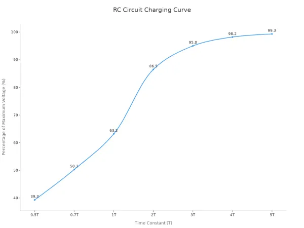
The charging process is predictable, making the time constant of rc circuit a powerful design tool. Here is how the charge level increases with each time constant:
| Time Constant | Percentage of Maximum Voltage |
|---|---|
| 1τ | 63.2% |
| 2τ | 86.5% |
| 3τ | 95.0% |
| 4τ | 98.2% |
| 5τ | 99.3% |
This predictable curve is the foundation for using RC circuits in filters and timers.
RC circuits as signal filters

The predictable charging and discharging behavior of an RC circuit makes it an excellent tool for filtering electronic signals. A filter selectively allows certain frequencies to pass while blocking others. The time constant is the key that sets the filter's behavior.
Low-pass filters for signal smoothing
A low-pass filter allows low-frequency signals to pass through to the output. It blocks or attenuates high-frequency signals. This is useful for removing unwanted noise from a signal.
A simple RC low-pass filter places a resistor in series with the signal path and a capacitor in parallel with the load (from the signal path to ground). The capacitor's opposition to current flow, its impedance, is high for low frequencies. This allows low-frequency signals to pass to the output. For high frequencies, the capacitor's impedance is very low. It creates an easy path to ground, effectively shorting out high-frequency noise.
The time constant of rc circuit determines the cutoff frequency. This is the frequency at which the filter starts to work. Signals above this frequency are significantly reduced.
Practical Example: Smoothing a DC Power Supply A common use for a low-pass filter is in a DC power supply. After converting AC to DC, the voltage often has small, high-frequency fluctuations called "ripple." An RC low-pass filter can smooth this out. The filter's capacitor charges during voltage peaks and discharges during troughs, averaging out the ripple and providing a much smoother, stable DC output voltage.

High-pass filters for AC coupling
A high-pass filter does the opposite of a low-pass filter. It blocks low-frequency signals and allows high-frequency signals to pass. The most common low-frequency signal it blocks is 0 Hz, which is DC voltage.
In a high-pass filter, the capacitor is placed in series with the signal path, and the resistor is in parallel with the load. The capacitor blocks the DC component of an input signal. It only allows the changing (AC) part of the signal to pass through.
Practical Example: AC Coupling in Audio Amplifiers Audio signals are AC waveforms. Sometimes, these signals have an unwanted DC voltage added to them, known as a DC offset. This offset can cause problems for an amplifier. A high-pass filter is used for AC coupling to solve this. The series capacitor blocks the DC offset but allows the AC audio signal to pass through to the amplifier for clean, distortion-free sound.
The choice of capacitor is important for audio quality. A 10uF capacitor is a standard choice for AC coupling in many audio circuits. The component values determine the low-frequency response.
| Capacitor Value | Load Resistance | Approximate Low-Frequency Cutoff |
|---|---|---|
| 1µF | 16 kΩ | 10 Hz |
| 1µF | 1.6 kΩ | 100 Hz |
| 10µF | 16 kΩ | 1 Hz |
Using larger capacitors, like 100µF or 220µF, can help preserve the deepest bass frequencies, especially when the circuit's impedance might vary.
RC networks as timing elements
Beyond filtering, the predictable charge and discharge curve of an RC circuit makes it a perfect timing mechanism. This capability is the foundation for creating the regular pulses and deliberate delays that orchestrate operations in countless electronic systems.
Creating clock pulses with oscillators
An oscillator is a circuit that produces a continuous, repeating electronic signal, often a square wave or a sine wave. These signals act as the "heartbeat" or clock for digital circuits, synchronizing all their actions. RC networks are essential for building simple and effective oscillators.
RC oscillators use a resistor-capacitor network to control timing. They are primarily used for generating lower frequencies, such as those in the audio range. Several designs exist, each with specific strengths.
- RC Phase-Shift Oscillator: This design is known for its simple structure and low cost. However, its output waveform can be poor, making it suitable for applications with less strict requirements.
- Wien Bridge Oscillator: This type is widely used because it starts easily and produces a good quality output waveform. It also offers convenient frequency adjustment.
- Astable Multivibrator: This is a very common type of relaxation oscillator. Its operation depends entirely on the charging and discharging cycles of its capacitors.
In an astable multivibrator, the frequency of the clock pulse is directly set by the resistor and capacitor values. For a common configuration, the frequency (
f) can be calculated with the formula:f = 1 / (1.38 * R * C).
A popular and versatile component for building oscillators is the IC 555 timer. In its astable mode, it generates a continuous stream of pulses. The frequency is determined by two resistors (R1, R2) and one capacitor (C).
| Component | Role in 555 Timer Oscillator |
|---|---|
| R1 & R2 | Control the charging time of the capacitor. |
| R2 | Controls the discharging time of the capacitor. |
| C | The timing capacitor that charges and discharges. |
The output frequency is calculated using the formula: Frequency = 1.44 / ((R1 + 2*R2) * C). By carefully selecting these R and C values, an engineer can design an oscillator that produces a clock pulse at a precise, desired frequency.
Generating delays for system resets
Microcontrollers (MCUs) and other complex chips need a stable power supply before they can start running their programs. If a chip tries to start while the voltage is still rising, it can enter an unknown state and fail to operate correctly. An RC network provides a simple and reliable solution: the power-on reset (POR) circuit.
A POR circuit uses the time constant of rc circuit to create a brief delay, ensuring the MCU stays in a reset state until the power supply is stable. The process is straightforward:
- When the system is powered on, the capacitor in the RC circuit begins to charge through the resistor.
- The voltage across the capacitor is connected to the MCU's
RESETpin. While this voltage is low, the MCU is held in a reset state. - The capacitor continues to charge. The voltage across it rises exponentially.
- Once the voltage reaches a specific threshold (e.g., a high logic level), the
RESETpin is released. - With the reset signal removed, the microcontroller begins its normal startup sequence and runs its program.
This precise control over system startup is fundamental in modern electronics. Companies like Nova Technology Company (HK) Limited, a HiSilicon-designated (authorized) solutions partner, leverage deep expertise in these principles. Their work in creating robust chip-level solutions and system integrations relies on the flawless execution of timing functions, including power-on resets, to ensure device reliability. The delay time is directly proportional to the R * C product, allowing designers to customize the reset duration for any system's needs.
RC circuits in digital logic
The influence of RC circuits extends deep into the world of digital logic. Here, they solve physical-world problems and manage the fundamental characteristics of high-speed signals.
Debouncing mechanical switches
Mechanical switches seem simple, but they can create a problem called contact bounce or chatter. When you press a button, the metal contacts do not make a single, clean connection. Instead, they bounce against each other for a few moments. This creates a series of rapid, unwanted electrical pulses from a single physical press. A microcontroller might see this as multiple presses, causing errors like extra characters when typing.
An RC circuit acts as a simple low-pass filter to solve this issue. It smooths out the noisy signal from the switch.
How it Works: A resistor and capacitor are placed at the switch's output. When the switch bounces, the capacitor charges and discharges slowly. This filters out the fast, erratic voltage spikes. The output becomes a single, smooth transition from low to high.
The effectiveness of this solution depends on the time constant of rc circuit. The time constant must be long enough to ignore the bounce (typically a few milliseconds) but short enough that the user does not feel a delay. A common combination is a 10kΩ resistor and a 0.1μF capacitor.
Managing signal rise time
In high-speed digital electronics, signals must switch between high and low states very quickly. Rise time measures how quickly a signal transitions from a low voltage (logic '0') to a high voltage (logic '1'). This is a critical parameter. A slow rise time can cause a digital chip to miss data or fail to operate correctly.
Every circuit board trace has tiny amounts of resistance and capacitance, known as parasitic effects. Together, they form an unintentional RC circuit.
- The Problem: This parasitic RC network can slow down a signal's rise time. A longer trace or poor layout increases these parasitic values.
- The Consequence: A larger parasitic R and C product results in a longer time constant, which slows the signal's edge. This can limit the maximum operating speed of the entire system.
Engineers use specific design techniques to manage these effects and ensure fast rise times. They carefully control the width of circuit traces and route critical signals on internal layers of the circuit board to maintain signal integrity.
The RC time constant is a versatile design tool. It unifies the concepts of filtering, timing, and signal integrity. This single principle allows engineers to reduce noise in ECG signals, shape pulses for spectroscopy, and manage the frequency response of high-speed circuits. You can find its application in almost every electronic gadget, from phone chargers to audio gear.
The formula
τ = R * Cis more than a calculation. It is a practical lever for controlling circuit speed and behavior.
Mastering the time constant is a key step. It helps you advance from assembling circuits to designing them with intent and precision.
FAQ
What happens if the time constant is too short or too long?
A short time constant (τ) creates a fast response. This is good for high-speed signals but poor for filtering noise. A long time constant creates a slow response. This is excellent for smoothing power supplies but can delay important signals in a circuit.
How do I choose R and C values?
The choice depends on your goal. For filtering, the values set the cutoff frequency. For timing, they set the delay duration.
First, determine the time constant your application needs. Then, select practical resistor and capacitor values that multiply to that time constant.
Does the source voltage affect the time constant?
No, the source voltage does not change the time constant. The formula is τ = R * C. It only depends on the resistance and capacitance values. Voltage affects the final charge level, not the charging rate.
Can I use the 5τ rule for discharging too?
👍 Yes, the 5τ rule applies to discharging as well. After five time constants, a capacitor is considered fully discharged. Its voltage will have dropped to less than 1% of its initial value, which is effectively zero for most practical applications.