

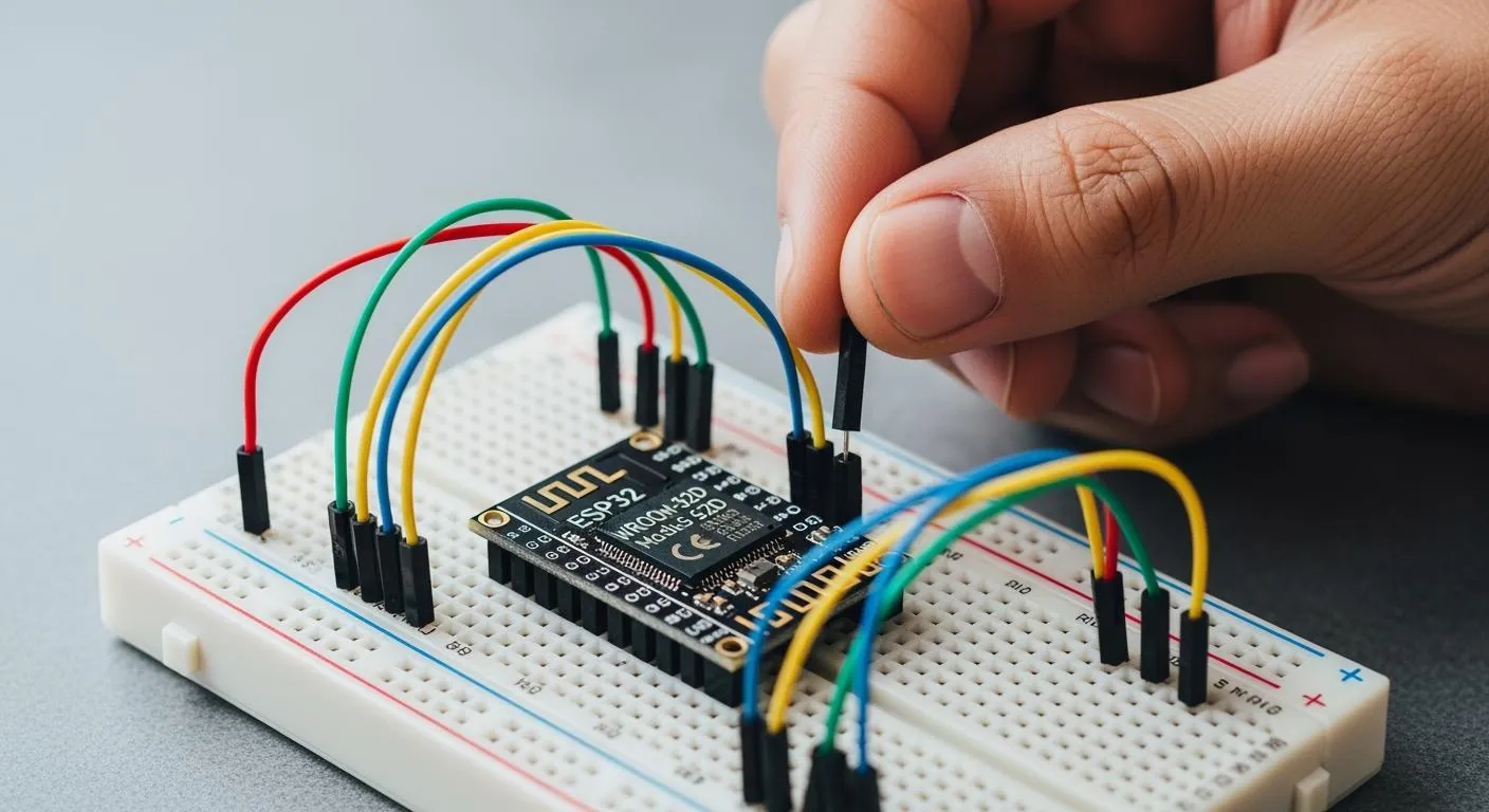
How to Set Up ESP32-WROOM-32D on a Breadboard
How to breadboard ESP32-WROOM-32D: solder to a breakout adapter, connect power, ground, and serial lines, and program your module for reliable IoT prototyping.
If you want to learn how to breadboard esp32-wroom-32d, you need to start with the right tools. For this tutorial, grab an esp32-wroom-32d, a breakout adapter, a breadboard, jumper wires, a USB-to-serial adapter, and a stable 3.3V power supply. You’ll find breadboard esp32-wroom-32d tricky because of the microcontroller’s pin spacing, the need for reliable 3.3V power, and the special serial programming interface. This tutorial helps you overcome those issues. With breadboard esp32-wroom-32d, you can build iot prototypes, test wi-fi and bluetooth features, and make breadboard esp32-wroom-32d a core part of your wi-fi projects. This tutorial gives you hands-on experience with breadboard esp32-wroom-32d for iot prototyping and microcontroller-based iot devices.
Key Takeaways
- Gather essential components like the ESP32-WROOM-32D, breakout adapter, and a stable 3.3V power supply to start your project.
- Use a breakout adapter to connect the ESP32 module to the breadboard, ensuring proper pin spacing and avoiding damage.
- Always check your power supply voltage; connecting 5V can damage the ESP32. Use capacitors for stable operation.
- Program the ESP32 using a USB-to-serial adapter, and ensure correct wiring to avoid upload errors.
- Take your time with each setup step; careful preparation prevents troubleshooting headaches later.
Components Needed for Breadboard ESP32-WROOM-32D
ESP32-WROOM-32D Module and Breakout Adapter
You need the right hardware to get your esp32 project started. Grab an esp32-wroom-32d module. This module packs wi-fi and bluetooth features, making it perfect for iot and breadboard esp32 prototyping. The wroom module has tiny pads spaced at 2.00mm, which don’t fit standard breadboards. You need a 2.00mm-to-2.54mm breakout adapter. This adapter converts the pad spacing to breadboard-friendly headers. You can easily insert the module into your breadboard and connect jumper wires. You avoid soldering wires directly to the esp32-wroom-32d, which keeps your setup neat and reliable.
Tip: A breakout adapter makes testing and repairs much easier. You can also transition your breadboard esp32 project to a custom PCB later.
If you want professional support for chip-level solutions and system integration, Nova Technology Company (HK) Limited is a HiSilicon-designated solutions partner. Nova specializes in semiconductor applications, advanced IC integration, and offers expertise for wi-fi, bluetooth, and iot scenarios.
Breadboard and Power Supply (3.3V)
Pick a standard breadboard for your esp32-wroom-32d setup. Make sure your breakout adapter fits snugly. You need a stable 3.3V power supply. The esp32 runs at 3.3V, so never connect 5V directly. Use a 3.3V regulator to protect your wroom module. Place a 10uF capacitor and a 0.1uF capacitor near the power pins. These capacitors help stabilize the voltage and prevent random resets or brownouts. Reliable power keeps your esp32 running smoothly.
USB-to-Serial Adapter and Wires
You need a USB-to-serial adapter to program your esp32-wroom-32d. This adapter connects your computer to the esp32 for uploading code and debugging. Choose a USB-to-TTL serial adapter that works with 3.3V logic. Grab jumper wires to connect everything. You also need two push buttons for boot and reset functions. Optional: Use a logic level shifter if you want extra protection for your wroom module.
Here’s a quick list of what you need:
- esp32-wroom-32d module
- 2.00mm-to-2.54mm breakout board
- Standard breadboard
- Male header pins
- 3.3V regulator
- 10uF capacitor
- 0.1uF capacitor
- USB-to-TTL serial adapter
- Two push buttons
- Jumper wires
- Optional logic level shifter
You now have all the essential components to build your breadboard esp32 project. With these tools, you can start experimenting with wi-fi, bluetooth, and iot features.
Key Challenges When You Breadboard ESP32
Setting up the esp32-wroom-32d on a breadboard can feel like a puzzle. You might run into a few common problems, but don’t worry—there are simple fixes for each one. Let’s break down the main challenges and how you can solve them.
Pin Spacing and Breadboard Fit
The first thing you’ll notice is that the esp32-wroom-32d doesn’t fit your breadboard. The wroom module uses 2mm pin spacing, while standard breadboards use 2.54mm. This mismatch means you can’t plug the esp32 directly into the breadboard. If you try, the pins won’t line up with the holes, and you risk bending or damaging them.
Here’s what you can do:
- Use a breakout board to convert the 2mm spacing to 2.54mm. This adapter lets you insert the wroom module into your breadboard without hassle.
- Solder the esp32-wroom-32d onto the breakout board, then add male header pins. Now you can use jumper wires to connect everything.
- Double-check the orientation of the pins before powering up.
Tip: A breakout board not only solves the fit issue but also makes your breadboard esp32 project much easier to debug and upgrade.
Power Supply Issues
The esp32 needs a stable 3.3V power supply. Many users accidentally connect 5V, which can damage the wroom module. The pins on the esp32 are sensitive, so always check your voltage before powering up.
Common power problems include:
- Unstable voltage from cheap regulators.
- Insufficient current, especially when using wi-fi or bluetooth features.
- Upload failures caused by poor ground connections.
To avoid these issues:
- Use a quality 3.3V regulator and add a 10uF and 0.1uF capacitor near the power pins.
- Never connect the esp32 to more than 3.3V.
- If you connect to higher voltage devices, use level shifters or voltage dividers to protect the pins.
Serial Programming Interface
Programming the esp32-wroom-32d is different from plugging in a USB cable. The module doesn’t have a built-in USB port, so you need a USB-to-serial adapter. This extra step can trip up beginners.
Here are some common issues and solutions:
| Common Issue | Recommended Solution |
|---|---|
| Failed Uploads | Hold GPIO0 low during reset to enter bootloader mode. |
| Power Supply Problems | Use a reliable 3.3V source with enough current to avoid resets. |
| Driver Issues | Install the correct USB-to-Serial drivers for your operating system. |
| Port Selection | Make sure you select the right COM port in your development environment. |
| Boot Loops | Check your code for watchdog timer problems or continuous resets. |
If you wire the serial pins incorrectly or miss a ground connection, uploads will fail. Always double-check your connections before you start programming.
With these tips, you can tackle the main challenges of breadboarding the esp32-wroom-32d. Once you get the hang of it, you’ll find the esp32 perfect for iot projects, wi-fi experiments, and custom wroom-based designs.
How to Breadboard ESP32-WROOM-32D: Step-by-Step
Ready to bring your esp32 project to life? Let’s walk through the setup process, from soldering to your first test. You’ll learn how to connect esp32 to breadboard, wire everything for reliable operation, and avoid the most common mistakes. Grab your tools and let’s get started!
Soldering to a Breakout Board
First, you need to attach your esp32-wroom-32d module to a breakout adapter. The wroom module’s 2mm pin spacing won’t fit a standard breadboard. The breakout board converts those tiny pads to breadboard-friendly headers. Place the esp32-wroom-32d on the adapter, making sure the pins line up with the labels. Solder each pin carefully. Take your time—good solder joints mean fewer problems later.
Tip: If you’re new to soldering, practice on spare header pins before working on your wroom module. Avoid cold joints and bridges between pins.
Many beginners skip this step or rush through it. Don’t! A solid solder job gives you a stable foundation for the rest of your setup.
Inserting ESP32-WROOM-32D into Breadboard
Once you finish soldering, insert the breakout board into your breadboard. Make sure the pins sit straight and the board fits snugly. Leave enough space on both sides for jumper wires. You want easy access to all the pins for wiring. Double-check the orientation—match the labels on the breakout with your breadboard layout.
If you force the board or misalign the pins, you risk damaging the esp32 or the breadboard. Take a moment to plan your layout. This step makes wiring much easier and keeps your setup neat.
Wiring Power, Ground, and Boot Pins
Now, let’s handle the most important wiring: power, ground, and boot pins. The esp32 needs a stable 3.3V supply. Never connect 5V directly to the module. Use a 3.3V regulator and place a 10uF and 0.1uF capacitor near the power pins for smooth operation.
Here’s a quick reference for wiring the essential pins:
| ESP32-WROOM-32D Pin | Connection |
|---|---|
| 3V3 | Stable 3.3V Power |
| GND | Common Ground |
| EN / CHIP_PU | Pull Up To 3.3V |
| GPIO0 | BOOT Button To GND |
| GPIO2 | Keep Safe For Boot |
| GPIO12 / MTDI | Avoid Pulling High At Boot |
| GPIO15 / MTDO | Avoid Wrong Boot Pull State |
Connect the 3V3 pin to your regulated 3.3V supply. Tie all GND pins to a common ground rail on the breadboard. Pull the EN (or CHIP_PU) pin up to 3.3V using a 10kΩ resistor. Add a push button between GPIO0 and GND for boot mode. Place another button between EN and GND for reset. Keep GPIO2, GPIO12, and GPIO15 in their safe states during boot to avoid startup issues.
Note: Double-check your wiring before powering up. Incorrect connections can prevent the esp32 from booting or even damage the module.
Connecting USB-to-Serial Adapter
To program your esp32-wroom-32d, you need a USB-to-serial adapter. This device lets your computer talk to the esp32 for uploading code and debugging. Use an adapter that supports 3.3V logic, such as CP2102, CH340, FT232, or FTDI.
Follow these steps for proper wiring:
- Connect the U0TXD pin on the esp32 to the RX pin on the USB-to-serial adapter.
- Connect the U0RXD pin on the esp32 to the TX pin on the adapter.
- Tie the GND pins of both the esp32 and the adapter together.
- Make sure your adapter is set to 3.3V logic. Check the jumper position to avoid sending 5V to the esp32.
- If your adapter does not support auto-reset, use the manual upload sequence: Hold the BOOT button, press and release RESET, then release BOOT when the upload starts.
Tip: Label your wires or use color-coded jumpers. This helps you avoid mix-ups during setup and troubleshooting.
First Power-Up and Testing
You’re almost ready to test your setup. Start with a minimal circuit: connect 3.3V, GND, EN pull-up, BOOT button, RESET button, TX, and RX. Power up your breadboard esp32 and watch for signs of life.
Here’s a simple checklist for your first test:
- Upload a basic blink or serial print program. This confirms your wiring, boot mode, and serial connection.
- Open your serial monitor. Look for output from the esp32. If you see messages, your setup works!
- After you test your setup, add more components like LEDs, sensors, or relays. Expand your iot project step by step.
- Use a simple serial print sketch for your first upload. This checks UART wiring, boot mode, reset button, USB driver, and power supply.
- Once you see serial output, try a wi-fi scan sketch to confirm wireless features.
⚠️ Common mistakes include using the wrong pin spacing, unstable power supplies, missing programming interfaces, and poor soldering. Take your time with each step. Careful setup now saves hours of troubleshooting later.
Breadboarding esp32 gives you hands-on experience with microcontrollers, wi-fi, and iot. With the right wiring and careful setup, you’ll have a reliable platform for prototyping and learning. Enjoy building your next project!
Programming and Troubleshooting ESP32-WROOM-32D
Setting Up Arduino IDE
You want to program the esp32 development board on your breadboard, so you need to set up the Arduino IDE first. Follow these steps to get started:
- Download the Arduino IDE installer from the official site and install it.
- Add the ESP32 board support URL in the preferences.
- Open the Board Manager and install the ESP32 package.
- Select the correct esp32 development board from the Tools menu.
- Configure board settings like Flash Size and Partition Scheme.
- Upload a test sketch, such as Blink, to verify your setup.
You might run into issues like the IDE not recognizing your esp32 development board’s serial port, failed uploads, or pins not working as expected. If you see these problems, check your drivers and make sure you selected the right board and port.
Tip: Always double-check your breadboard connections before you program the esp32. Loose jumper wires can cause strange errors.
Uploading Code to ESP32
When you program the esp32-wroom-32d, you need to upload code through the USB-to-serial adapter. Open Arduino IDE and go to File > Examples > 01.Basics > Blink. Select your esp32 development board and the correct port. Examine the code, then click Upload. The IDE will compile and transfer the sketch to your esp32.
If you see error messages like “ESP32 Board Not Detected” or “Upload Timeout,” try lowering the upload speed to 115200 baud. Sometimes you need to manually put the esp32-wroom-32d into boot mode by holding the BOOT button during reset. Make sure all drivers are installed and your USB cable is secure.
Note: If your esp32 development board overheats, disconnect it right away. Check your power supply and make sure you use 3.3V.
Troubleshooting Power and Serial Issues
Power and serial problems can stop your breadboard esp32 project. Here are some quick fixes:
- Use a steady 3.3V power supply for the esp32-wroom-32d.
- Check all ground connections before measuring voltage.
- Use a voltmeter to verify voltages with the board unplugged.
- Try a lower baud rate if upload errors happen.
- Disconnect other devices from the esp32 pins during programming.
- Never power the esp32 development board with 5V directly.
Here’s a handy table for common issues:
| Problem | Likely Cause | Fix |
|---|---|---|
| No Serial Port | USB Driver Missing | Install Adapter Driver |
| Upload Fails | Wrong TX/RX Wiring | Swap TX and RX |
| Timed Out Waiting For Packet | Not In Boot Mode | Hold BOOT and Reset |
| Brownout Reset | Weak 3.3V Supply | Use Better Regulator |
| Wi-Fi Disconnects | Antenna Blocked | Clear Antenna Area |
| Board Boots Only Sometimes | Strapping Pin Conflict | Check GPIO0, GPIO2, GPIO12, GPIO15 |
| Module Gets Hot | Wrong Voltage | Disconnect Immediately |
Tips for Stable Breadboard ESP32 Operation
You want your breadboard esp32 development board to run smoothly. Here are some tips:
- Keep jumper wires short to reduce noise.
- Use quality capacitors near the power pins.
- Always check your breadboard layout before you program the esp32.
- Avoid connecting other devices to the wroom pins during programming.
- Press the reset button if you lose connection.
⚡ Stable power and careful wiring make programming the esp32 easier. You can build reliable iot projects and test new ideas with your breadboard setup.
Breadboard ESP32 vs. Dev Boards and Next Steps
Pros and Cons of Breadboard ESP32
You might wonder if using a breadboard for your esp32 project is the best choice. Let’s look at the ups and downs. Breadboard setups give you flexibility. You can change your wiring, swap sensors, and test new ideas fast. If you make a mistake, you just move a jumper wire. You don’t need to worry about soldering everything right away.
Here’s a quick list of pros:
- Easy to experiment with esp32 and wroom modules.
- No need for permanent soldering.
- Great for learning and prototyping.
- Quick changes for testing features.
But breadboard esp32 setups also have some drawbacks:
- Connections can get loose or messy.
- Power issues pop up if you use long jumper wires.
- Breadboard layouts don’t work well for bigger projects.
- You might see random resets or glitches if the wiring isn’t solid.
Dev boards solve many of these problems. They come with built-in USB ports, voltage regulators, and stable connections. You don’t need to worry about pin spacing or boot mode buttons. If you want a reliable platform for daily use, dev boards make things easier.
Tip: Use a breadboard esp32 for quick iot prototypes. Switch to a dev board when you need stability or want to build something permanent.
When to Move to PCB or Production
You start with a breadboard esp32 to test your wroom module and ideas. When your project works and you want to make it last, it’s time to move to a custom PCB. PCBs give you strong connections, compact layouts, and professional results. You can design your own board with the exact features you need.
Here’s a simple table to help you decide:
| Stage | Best Platform |
|---|---|
| Learning | Breadboard esp32 |
| Prototyping | Breadboard or Dev Board |
| Final Product | Custom PCB with wroom |
If you plan to sell your device or use it in the field, a PCB is the way to go. You get better performance and fewer problems. You can also add custom chips, connectors, and sensors.
Note: Moving to production means you need to think about system integration, chip-level solutions, and reliable power. Make sure your esp32 and wroom module fit your application.
You can always start with a breadboard esp32, then upgrade to a dev board or PCB as your project grows. This path helps you learn, test, and build better devices.
You’ve learned how to set up the esp32 on a breadboard for your next iot project. Here’s a quick recap of the steps:
- Gather all parts, including the esp32 module, breakout board, and power supply.
- Solder the esp32 to the breakout board.
- Insert the module into your breadboard and connect power, ground, and serial lines.
- Use a 3.3V regulator and add capacitors for stability.
- Program the esp32 with Arduino IDE.
Before you upload code, check your wiring and power. Use this table for safety:
| Safety Precaution | Description |
|---|---|
| Use One Power Option | Only power the esp32 one way at a time. |
| Ensure Power Stability | Use a clean 3.3V supply to avoid resets. |
| Add Capacitors | Place 10uF and 0.1uF capacitors near power pins. |
Try building a smart LED controller or a home automation system next. Don’t forget to experiment and share your results!
FAQ
What power supply should I use for ESP32-WROOM-32D on a breadboard?
You need a stable 3.3V power supply. Never use 5V. A low-dropout regulator works best. Add a 10uF and a 0.1uF capacitor near the power pins for extra stability.
Can I program ESP32-WROOM-32D without a USB port?
Yes! You use a USB-to-serial adapter. Connect TX, RX, and GND. Hold the BOOT button during reset to enter programming mode. The Arduino IDE handles the rest.
Why won’t my ESP32 boot on the breadboard?
Check your wiring. Make sure EN is pulled up to 3.3V. Double-check power and ground. If you see random resets, your power supply might be unstable.
Do I need to solder the ESP32-WROOM-32D?
Yes, you must solder the module to a breakout board. The pins are too close together for direct breadboard use. Soldering gives you reliable connections.
What’s the difference between a breadboard setup and a dev board?
A dev board has built-in USB, voltage regulator, and buttons. Breadboard setups need more wiring and parts. You get more flexibility with a breadboard, but dev boards are easier for beginners.


