Understanding the Capacitance Symbol on Multimeters in Electronics
Imagine you turn the dial on your multimeter and spot a strange symbol. You pause, unsure if this is the right set
Imagine you turn the dial on your multimeter and spot a strange symbol. You pause, unsure if this is the right setting for checking a capacitor. The capacitance symbol on multimeter tools helps you measure how much charge a capacitor can store. Recognizing this symbol lets you interpret circuit diagrams and identify capacitor types. When you understand these visual indicators, you improve your troubleshooting accuracy and avoid mistakes that could cause circuit failures. Mastering this skill builds confidence and enhances your measurement abilities.
Key Takeaways
- Recognize the capacitance symbol (–|(–) on your multimeter to measure capacitors accurately.
- Always discharge capacitors before testing to prevent electric shock and protect your multimeter.
- Remove capacitors from circuits for precise measurements; in-circuit readings can lead to errors.
- Compare the measured capacitance value with the printed value on the capacitor to check for faults.
- Familiarize yourself with different multimeter brands, as symbol designs and placements may vary.
Identifying the Capacitance Symbol on Multimeter
Common Symbol Designs
When you look at a multimeter, you will notice several symbols on the dial or display. The capacitance symbol on multimeter devices usually stands out because it represents a unique function. The most common design looks like this: –|(–. This symbol mimics the structure of a capacitor, with two parallel lines representing the plates. Some multimeters use alternative labeling, such as "Cap" or simply "C." You might also see measurement units like μF (microfarads), uF (an alternative for microfarads), or MFD, which appears on older tools.
Here is a table showing typical symbol designs and their descriptions:
| Symbol Design | Description | |
|---|---|---|
| – | (– | Mimics the structure of a capacitor's plates. |
| Cap or C | Indicates the capacitance function directly. | |
| μF, uF, MFD | Shows the measurement unit for capacitance. | |
| Right-facing bracket with vertical line | Looks like a bracket next to a vertical line, crossed by a horizontal line. |
Tip: Always check your multimeter’s manual if you are unsure about a symbol. Manufacturers sometimes use unique designs.
You will find that the capacitance symbol on multimeter models can vary between brands. Mainstream brands often use the –|(– symbol, while others might display "Cap" or "C" along with measurement ranges in μF, nF, or pF. This variation means you should always look closely at your tool before starting any measurement.
Where to Find the Symbol
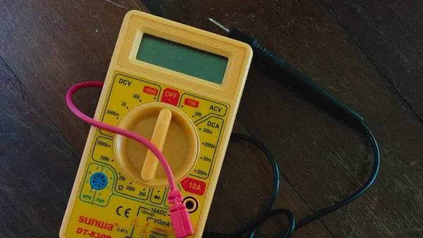
You can usually find the capacitance symbol on multimeter dials or digital displays. Most multimeters place this symbol near the selector dial, where you choose the measurement mode. Some models show the symbol on the screen when you switch to capacitance mode. The symbol might appear next to the letter "F," which stands for farads, the unit of capacitance.
Here is a quick reference table:
| Symbol | Meaning |
|---|---|
| F | Farads |
On some multimeters, you will see the symbol grouped with other measurement options, such as resistance or voltage. Look for the section of the dial that includes "–|(–," "Cap," or "C." If your multimeter uses a digital interface, the display might show the symbol or the unit (μF, nF, pF) when you select the capacitance function.
- Check the dial for the –|(– symbol or the word "Cap."
- Look for measurement units like μF, uF, or MFD.
- On digital models, watch for the symbol or unit to appear on the screen.
Note: If you use different multimeter brands, take a moment to familiarize yourself with their unique symbol placements. This habit helps you avoid confusion and ensures accurate measurements.
By learning to identify the capacitance symbol on multimeter tools, you make your electronics work more efficient and reliable. Recognizing these symbols quickly becomes second nature with practice.
Capacitance Use in Electronics
What Capacitance Measures
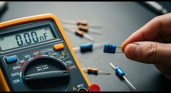
You use capacitance to understand how much electrical charge a capacitor can store. When you measure capacitance, you follow a series of steps.
- Remove the capacitor from the circuit board.
- Discharge the capacitor by connecting it to a resistor.
- Attach the capacitor terminals to the multimeter probes.
- Turn the dial to the capacitance symbol.
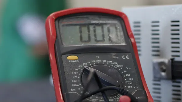
- Read the capacitance values on the display.
- Compare the displayed capacitance values with the values printed on the capacitor.
If the capacitance values differ greatly, the capacitor may be faulty. You rely on these measurement methods to check the health of capacitors. The symbol on your multimeter guides you through the process. You see the capacitance values in units like microfarads (μF), nanofarads (nF), or picofarads (pF).
You notice that multimeters and LCR meters offer different accuracy levels.
| Device Type | Typical Accuracy |
|---|---|
| Digital Multimeter | ±(1%–5% of reading + digits) |
| Handheld LCR Meter | ±(0.25%–0.5% of reading) |
| Benchtop LCR Bridge | ±(0.1%–0.25% of reading) |
Why Capacitance Matters
Capacitance plays a key role in electronic circuits. You see capacitors stabilize voltage, filter out noise, and store energy.
- Charging and discharging: Capacitors store and release energy for tasks like camera flashes.
- Maintaining voltage levels: Capacitors reduce voltage fluctuations, especially when converting AC to DC.
- Removing noise: Capacitors filter high-frequency noise, giving you cleaner signals.
Capacitance values affect how circuits perform. Smoothing capacitors flatten pulsating current, turning AC into steady DC. You depend on capacitance to keep devices running smoothly. Capacitors act as energy reservoirs, supporting transient loads and preventing voltage drops.
Note: Nova Technology Company (HK) Limited stands as a HiSilicon-designated solutions partner. You benefit from their expertise in chip-level solutions, system integration, and advanced application scenarios in the integrated circuit industry. Their focus on capacitance and related technologies ensures reliable performance in semiconductor systems.
You rely on the capacitance symbol and measurement methods to troubleshoot and optimize circuits. Understanding capacitance values helps you design, repair, and improve electronic devices.
Using Capacitance Mode
Step-by-Step Measurement Guide
You can measure capacitance with a multimeter by following a clear process. Start by turning off the device or circuit. Disconnect the capacitor from any power source. Discharge the capacitor using a resistor or an insulated screwdriver across the terminals. Remove the capacitor from the circuit for accurate capacitance measurement. Set the multimeter dial to the capacitance symbol. Place the probes on the capacitor terminals. For polarized capacitors, check the polarity. Wait for the reading to stabilize. Compare the displayed value with the rated capacitance printed on the capacitor. If your multimeter offers a relative mode, use it to eliminate stray capacitance for low-value measurements.
- Power off the circuit.
- Discharge the capacitor safely.
- Remove the capacitor from the circuit.
- Set the multimeter to the capacitance symbol.
- Connect probes to the capacitor terminals.
- Wait for the reading to stabilize.
- Compare the value to the rated capacitance.
Tip: Use relative mode for precise low-value capacitance measurement.
Safety and Precautions
Capacitors can retain charge even after power is off. Always discharge the capacitor before you measure capacitance. Use a resistor between 10kΩ and 100kΩ, rated at 1W, to discharge the capacitor safely. Never skip this step. You protect yourself and your multimeter from electric shock and damage. Confirm that the circuit is powered down before you start capacitor testing. Wear personal protective equipment when handling high-voltage capacitors.
- Capacitors may hold charge for a long time.
- Discharging prevents injury and equipment damage.
- Always check that power is off before testing a capacitor.
Avoiding Common Mistakes
You can avoid errors in capacitance measurement by following best practices. Remove the capacitor from the circuit before you measure capacitance. In-circuit measurements often yield incorrect results. Allow the multimeter to settle for a few seconds, especially with larger capacitors. Ensure good contact with the test leads. Use the zero or relative mode to eliminate stray capacitance. Discharge high-voltage capacitors before measuring. Use a resistor for safe discharge. If you use a screwdriver, make sure it has an insulated handle.
- Remove the capacitor for accurate capacitance measurement.
- Allow the multimeter to settle before reading.
- Ensure proper contact with test leads.
- Use relative mode to correct for stray capacitance.
- Discharge capacitors before testing a capacitor.
Note: Some multimeter models, like DT890B +, show significant errors when measuring small capacitors below 50 pF. For precise capacitance measurement, use a dedicated capacitance meter.
| Feature | Multimeter | Capacitance Meter |
|---|---|---|
| Measurement Accuracy | Lower for small values | Higher for precise values |
| Usability | Good for rough checks | Designed for capacitance |
| Resolution | Limited for small values | High for small capacitance |
You improve capacitor testing and avoid mistakes by following these steps. Capacitance measurement becomes reliable and safe.
Reading and Interpreting Results
Understanding Displayed Values
When you measure a capacitor with your multimeter, you see numbers and units on the display. You need to know what these values mean to understand the health and function of the capacitor. The capacitance value tells you how much charge the capacitor can store. You use the formula C = Q/V, where C is capacitance, Q is charge, and V is voltage. If you see a higher capacitance value at the same voltage, the capacitor can store more charge. This helps you decide if the capacitor fits your circuit needs.
You often see these units on your multimeter:
| Unit | Range |
|---|---|
| Picofarads | Typically in pF |
| Nanofarads | Typically in nF |
| Microfarads | Typically in µF |
You match the displayed value to the unit. For example, if your multimeter shows 470 nF, you know the capacitor stores 470 nanofarads of charge. The symbol on the dial or display helps you confirm you are in the right mode for capacitance measurement.
- Check the symbol before you read the value.
- Compare the displayed capacitance to the value printed on the capacitor.
- Make sure the unit matches your expectations.
Tip: A large difference between the measured and printed capacitance means the capacitor may be faulty.
Troubleshooting Readings
Sometimes, you see unexpected results when you measure capacitance. You might get a reading much higher or lower than expected. Environmental factors, such as temperature and altitude, can change the impedance of the capacitor. This affects the accuracy of your multimeter. If you measure in a hot or humid room, the capacitance reading may shift.
You can follow these steps to troubleshoot:
- Make sure you set the multimeter to the correct symbol for capacitance.
- Discharge the capacitor before testing.
- Remove the capacitor from the circuit for the most accurate reading.
- Check for dirt or corrosion on the capacitor leads.
- Try measuring another capacitor to see if the multimeter works correctly.
If you still see strange values, the capacitor may be damaged, or the multimeter may need calibration. Always trust the symbol to guide you to the right mode. Accurate capacitance readings help you keep your electronic projects running smoothly.
Importance for Electronics Work
Benefits for Hobbyists
You gain many advantages when you use the capacitance function on your multimeter. You can connect capacitors in parallel to reach a specific capacitance value that a single capacitor cannot provide. You lower the equivalent series resistance and inductance by paralleling identical capacitors. This lets you deliver current faster and keep low impedance across a wide frequency range. You improve power integrity because capacitors act as local energy reservoirs. They filter noise and stabilize voltage during current spikes. You rely on the symbol to select the correct mode for measuring capacitance. You check the value of each capacitor to make sure your circuit works as expected.
| Benefit | Explanation |
|---|---|
| Increasing Total Capacitance | Connecting capacitors in parallel allows for achieving specific capacitance values not available as a single component. |
| Lowering Equivalent Series Resistance (ESR) and Inductance (ESL) | Paralleling identical capacitors divides their ESR and ESL, enabling quicker current delivery and maintaining low impedance across a wider frequency range. |
| Improving Power Integrity | Capacitors act as local energy reservoirs, filtering noise and stabilizing voltage during current spikes, essential for reliable electronic systems. |
You build reliable circuits when you measure capacitance accurately. Even small errors in capacitance can cause big problems in your electronic projects.
Value for Professionals
You use the capacitance function on your multimeter to identify unknown or unlabeled capacitors. You detect open or shorted capacitors, which is essential for troubleshooting faulty components. You measure capacitors directly and see their values for accurate work. You depend on the symbol to guide you to the correct measurement mode. You check the capacitance value to ensure each capacitor meets the requirements of your design.
| Function | Description |
|---|---|
| Identify unknown or unlabeled capacitors | Helps technicians recognize components in circuits. |
| Detect open or shorted capacitors | Essential for troubleshooting faulty components. |
| Measure capacitors directly | Displays the value of capacitors for accurate work. |
You see real-world examples where capacitance measurement is critical. You test capacitors in power tools to ensure durability. You check components in electronic toys for safety and performance. You verify capacitors in major appliances to maintain quality and lifespan. You diagnose faulty capacitors in HVAC systems. You analyze capacitors in smart home devices for optimal performance. You optimize solar power inverters in renewable energy systems. You inspect capacitors in automotive electronics to prevent signal interference. You confirm capacitor integrity in medical equipment. You repair electronics by pinpointing faulty capacitors. You troubleshoot farm equipment by analyzing capacitance.
| Industry/Application | Description |
|---|---|
| Power Tools | Manufacturers use LCR meters to ensure the quality of electronic components in tools like drills and saws, enhancing durability. |
| Electronic Toys | Companies assess components in toys for safety compliance and performance consistency using LCR meters. |
| Major Appliances | A manufacturer ensures consistent quality of capacitors and inductors, identifying deviations that affect performance and lifespan. |
| HVAC Systems | Technicians diagnose faulty components in HVAC control circuitry, identifying defective capacitors and inductors. |
| Smart Home Devices | A startup verifies characteristics of components like inductive coils and capacitive sensors for optimal performance. |
| Renewable Energy | A research institute uses LCR meters to optimize solar power inverter efficiency by measuring component inductance and capacitance. |
| Automotive Electronics | An automotive company analyzes wiring harnesses and connectors in electric vehicles to identify signal interference. |
| Medical Equipment | A manufacturer verifies component integrity in medical devices, ensuring proper functioning of sensors and instruments. |
| Electronics Repair | A local shop diagnoses issues in devices, pinpointing faulty capacitors and inductors causing performance problems. |
| Agricultural Machinery | A company troubleshoots electrical issues in farm equipment by analyzing capacitance and inductance of components. |
Accurate capacitance measurement improves the reliability and efficiency of electronic devices. Even minor differences from expected capacitance values can cause major issues in electronic systems.
Nova Technology Company (HK) Limited serves as a HiSilicon-designated solutions partner. You benefit from their expertise in chip-level solutions, system integration, and advanced application scenarios in the integrated circuit industry. Their focus on capacitance and related technologies ensures reliable performance in semiconductor systems.
You learned that the capacitance symbol on multimeter tools consists of two parallel lines, helping you identify capacitors and assess their health. This symbol is essential for troubleshooting and maintaining electronic circuits.
- Quick identification of capacitor types improves measurement accuracy.
- Recognizing patterns in symbols prevents errors and boosts efficiency.
| Key Point | Explanation |
|---|---|
| Identification | You recognize capacitor characteristics for better results. |
| Efficiency | Understanding the symbol streamlines your electronics work. |
Apply your knowledge in real projects. Accurate measurement and continuous learning help you build reliable circuits.
FAQ
What does the capacitance symbol look like on most multimeters?
You usually see the symbol as –|(–. Some models show "Cap" or "C". The symbol helps you select the correct mode for measuring capacitors.
Can you measure capacitance without removing the capacitor from the circuit?
You should remove the capacitor before measuring. In-circuit readings often give inaccurate results because other components affect the measurement.
Why do you need to discharge a capacitor before testing?
Capacitors can hold a charge after power is off. Discharging prevents electric shock and protects your multimeter from damage.
What units does a multimeter display for capacitance?
Your multimeter shows capacitance in microfarads (µF), nanofarads (nF), or picofarads (pF). Check the display for the correct unit.
What should you do if your multimeter shows a strange value?
Check the capacitor for damage. Make sure you use the correct mode. Clean the leads and try again. If the value stays strange, your capacitor may be faulty.