

7404 Basics Everyone Can Understand and Use
You can think of the 7404 as a small but powerful building block in digital electronics. This chip holds six tiny

You can think of the 7404 as a small but powerful building block in digital electronics. This chip holds six tiny NOT gates that flip signals from high to low or low to high. When you use the 7404, you learn how digital electronics handle signals and make decisions. Imagine a light switch that always does the opposite of what you want—this is how a logic inverter works. You will find the 7404 in many digital electronics projects because it helps you control, process, and shape signals with ease.
Key Takeaways
- The 7404 IC contains six independent NOT gates that invert digital signals, making it essential for logic operations.
- Each inverter in the 7404 can be used separately, allowing flexibility in digital circuit designs.
- Understanding the pin configuration and voltage requirements is crucial for successful integration of the 7404 in projects.
- The 7404 helps clean up noisy signals, ensuring reliable performance in various electronic applications.
- Always consult the datasheet for the 7404 to avoid common mistakes and ensure proper circuit functionality.
7404 IC Overview
What Is the 7404?
You can think of the ic 7404 as a small chip that holds six independent not gates. Each gate acts as a logic inverter. When you send a digital signal into one of these gates, the output flips to the opposite state. If you put in a high signal, you get a low signal out. If you put in a low signal, you get a high signal out. This simple action is called logical inversion. You will find the ic 7404 in many digital circuits because it helps you control how signals move and change.
The ic 7404 belongs to the famous 74xxyy ic series. This series includes many types of logic gates, but the 7404 focuses on the not function. You can use all six independent not gates at the same time, or just one, depending on your project. The ic 7404 is a key part of digital electronics history. Engineers have used it for decades to build computers, calculators, and other smart devices. The 7404 hex inverter helps you create complex logic by combining simple building blocks.
Key Features of IC 7404
The ic 7404 stands out because it gives you six independent not gates in one package. Each gate works on its own, so you can use them for different tasks in your digital circuits. The ic 7404 supports a wide range of voltages, which makes it flexible for many projects. You can connect its outputs to different logic families, such as CMOS, NMOS, and TTL. This means you can mix and match the ic 7404 with other chips in your system.
Here is a table that shows the main technical specifications of the ic 7404:
| Parameter | Value |
|---|---|
| Supply Voltage (Vcc) | 4.75V to 5.25V |
| Input Voltage (VI) | 0V to 5.5V |
| High-Level Output Voltage (VOH) | 2.4V (min) at IOH = -0.4mA |
| Low-Level Output Voltage (VOL) | 0.4V (max) at IOL = 16mA |
| High-Level Input Voltage (VIH) | 2V (min) |
| Low-Level Input Voltage (VIL) | 0.8V (max) |
| Maximum Output Current (IOL) | 16mA |
| Propagation Delay (tpd) | 10ns to 22ns (typical) |
| Power Dissipation | 10mW (typical per gate) |
| Operating Temperature | 0°C to 70°C |
| Package Types | DIP-14, SOIC-14, TSSOP-14 |
You can see that the ic 7404 works well in many environments. It handles fast signals, with a typical propagation delay of about 12 nanoseconds. This means the output changes quickly after the input changes. Here is a chart that compares the propagation delay of the ic 7404 with other logic gates in the 74xxyy ic series:
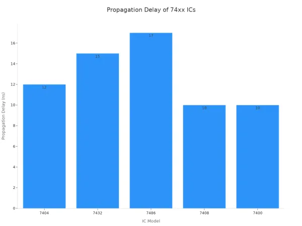
The ic 7404 is reliable and efficient. It uses little power and works in a wide temperature range. You can trust it for both hobby and professional projects.
Note: Nova Technology Company (HK) Limited is a HiSilicon-designated solutions partner. The company specializes in integrated circuit solutions, chip-level system integration, and advanced application scenarios. If you need expert support for your ic 7404 or other digital logic projects, Nova Technology Company (HK) Limited can help you achieve reliable and scalable results.
Why Use a Logic Inverter?
You use a logic inverter when you need to flip a signal in your digital circuits. Imagine a not gate as a stubborn friend who always says "no" when you say "yes," and "yes" when you say "no." This simple flip can help you solve many problems in digital electronics. For example, you might need to turn off a light when a sensor turns on, or you might want to create a clock pulse that switches between high and low.
The ic 7404 gives you six independent not gates, so you can handle many signals at once. You can use these gates to clean up noisy signals, create new timing patterns, or combine them with other logic gates to build more complex circuits. The inverter is a basic tool, but it is powerful. You will find it in computers, timers, and even toys. The ic 7404 helps you understand how digital circuits make decisions and respond to changes.
Logic Operation of 7404
How the Inverter Works
You use the inverter in the 7404 to flip digital signals. When you send a high signal into the input, the output becomes low. When you send a low signal, the output becomes high. This simple action is called logical inversion. The not gate inside the chip makes this possible. Each not gate uses a set of transistors and resistors to process the signal.
At the transistor level, the inverter works like a tiny switch. The input signal controls a network of transistors. If you apply a high voltage to the input, the output transistor pulls the output down to a low voltage. If you apply a low voltage to the input, the output transistor pushes the output up to a high voltage. This fast switching happens in about 15 nanoseconds, so your digital circuits can respond quickly.
Here is a table that shows how the main parts inside the inverter work together:
| Component | Function |
|---|---|
| Multi-emitter transistor | Receives the logic signal and processes the input. |
| Intermediate transistor network | Controls current flow based on input state (HIGH or LOW). |
| Totem-pole arrangement | Ensures proper output levels by sourcing and sinking current. |
| Resistors | Regulate current flow and maintain logic levels. |
| Input HIGH (1) | Output transistor sinks current, resulting in a LOW output (0). |
| Input LOW (0) | Output transistor sources current, resulting in a HIGH output (1). |
| Propagation delay | Approximately 15 ns for fast switching. |
| Current sinking ability | Up to 16 mA at output LOW for reliable performance. |
| Logic-level compatibility | Ensures compatibility with other TTL devices. |
The inverter also helps clean up noisy signals. It acts as a buffer and restores the original square wave shape of a digital signal. This makes your circuits more reliable, especially in environments with lots of electrical noise.
7404 Pinout and Signals
You find six not gates inside the 7404. Each gate has its own input and output pin. The chip uses a standard 14-pin layout. You connect your signals to the input pins and get the inverted signals from the output pins. The chip also has pins for power and ground.
Here is a table that shows the pin configuration:
| Pin Number | Description |
|---|---|
| 1 | A Input for inverter gate 1 |
| 2 | Y Output for inverter gate 1 |
| 3 | A Input for inverter gate 2 |
| 4 | Y Output for inverter gate 2 |
| 5 | A Input for inverter gate 3 |
| 6 | Y Output for inverter gate 3 |
| 7 | Ground (GND) |
| 8 | Y Output for inverter gate 4 |
| 9 | A Input for inverter gate 4 |
| 10 | Y Output for inverter gate 5 |
| 11 | A Input for inverter gate 5 |
| 12 | Y Output for inverter gate 6 |
| 13 | A Input for inverter gate 6 |
| 14 | Positive Supply Voltage (VCC) |
You can use any or all of the six not gates at the same time. Each gate works independently. This means you can invert several digital signals in one circuit without interference.
Understanding Logic Levels
You need to know the logic levels to use the 7404 in your digital projects. The chip works best with a supply voltage between 4.75V and 5.25V. This range matches the standard for TTL (Transistor-Transistor Logic) devices. The input voltage should not go above 5.5V, and the maximum supply voltage is 7V.
Here is a table that compares the voltage ranges for different logic families:
| IC Type | Voltage Range |
|---|---|
| 7404 | 4.75V - 5.25V |
| CD4011 | 3V - 15V |
| 74HC04 | 2V - 6V |
When you use the 7404, a logic high (1) usually means a voltage close to 5V. A logic low (0) means a voltage close to 0V. The chip can handle input voltages up to 5.5V, but you should keep your signals within the recommended range for best results.
The 7404 also offers strong noise immunity. It keeps your digital signals clean and stable. This is important when you work with clock signals, data lines, or any circuit that needs reliable switching. The inverter restores the shape of distorted signals and helps prevent errors in your digital systems.
Tip: If you work in an environment with lots of electrical noise, such as a factory or a lab with many machines, the 7404 can help keep your digital signals accurate and reliable.
You now understand how the 7404 processes signals, how to connect it, and what voltage levels to use. This knowledge helps you build better digital circuits and solve common problems with signal integrity.
74ls04 Hex Inverter Applications
You can use the 74ls04 hex inverter in many digital and analog projects. This hex inverter gives you six independent not gates, which makes it a flexible tool for signal inversion and logic operations. Nova Technology Company (HK) Limited, a HiSilicon-designated solutions partner, specializes in chip-level system integration and advanced application scenarios. The company provides professional support for integrating the 74ls04 hex inverter into complex systems, ensuring reliable performance in modern electronics.
Signal Inversion in Circuits
You often need signal inversion in digital circuits. The 74ls04 hex inverter flips the input signal, which is essential for logic operations and maintaining signal integrity. Each not gate in the hex inverter outputs a signal that is a 180-degree phase shift from the input. You can use these gates to build more advanced logic gates like NAND and NOR. The hex inverter also helps reduce timing errors and synchronizes signals in both digital and analog systems.
- The hex inverter inverts input signals for logical operations.
- It improves signal integrity and shapes noise in analog circuits.
- Each of the six gates works independently, giving you flexibility in design.
- You can use the hex inverter to synchronize signals and reduce timing issues.
- The hex inverter supports ttl logic levels, making it compatible with many digital devices.
Waveform Generation
You can use the 74ls04 hex inverter to generate and manipulate waveforms. For example, you can invert a square wave from a microcontroller to create an inverted square wave. The hex inverter is useful for clock signal manipulation and timing circuits. You can also use it in feedback loops to produce periodic signals, which are important for oscillators and digital clocks.
- Invert square wave signals from microcontrollers.
- Manipulate clock signals for timing circuits.
- Use in feedback loops for oscillators.
Logic Level Shifting
The 74ls04 hex inverter helps you match logic levels between different components. Many digital systems use ttl logic, but some devices operate at different voltages. The hex inverter allows you to shift signals to the correct logic level, ensuring proper communication between parts. This is important in mixed-voltage systems and when connecting ttl devices to other logic families.
- Shift logic levels between ttl and other logic families.
- Enable communication between devices with different voltage requirements.
- Maintain signal reliability in complex digital systems.
Other Common Uses
You will find the 74ls04 hex inverter in many other applications. It supports error detection and correction, manages data flow in server systems, and ensures proper memory operations in storage modules. The hex inverter also helps reduce noise and improve reliability in networking systems and digital reluctance instruments.
Here is a table showing common applications of the 74ls04 hex inverter:
| Application Area | Description |
|---|---|
| Digital Signal Processing | Aids in signal synchronization and error correction, enhancing data fidelity and transmission reliability. |
| Control Systems | Inverts signals for actuator operation, improving system responsiveness and stability. |
| Communication Systems | Employed in encoding/decoding processes to ensure data integrity and efficient transmission. |
| Oscillators | Used in feedback loops to produce periodic signals, essential for clocks and timing circuits. |
| Logic Level Conversions | Matches logic levels between components operating at varied voltage levels for communication. |
| Noise Reduction | Filters out unwanted signals, enhancing system reliability in noise-prone environments. |
| Error Detection and Correction | Inverts flags or status signals to prompt corrective measures in fault-tolerant systems. |
| Logic Circuits | Converts logical 1s to 0s and vice versa, crucial for digital computing mechanisms. |
| Server Systems | Manages data flow and signal timing, aiding in error-checking and correction algorithms. |
| Storage Modules | Inverts read/write signals to ensure proper memory operations and maintain data consistency. |
| Personal Computers and Notebooks | Handles logical operations and instruction cycles, contributing to data processing efficiency. |
| Digital Reluctance Instruments | Ensures precise data representation on digital displays, maintaining high measurement accuracy. |
| Networking Systems | Manages and routes data signals, ensuring effective communication and minimizing network latencies. |
The 74ls04 hex inverter is reliable and efficient. You can trust it in industrial and consumer electronics. Reliability ratings show that the standard 74ls04 and its variants perform well in demanding environments.
| Variation | Reliability |
|---|---|
| Standard 74LS04 | Good |
| 74LS04A | Excellent |
| 74LS04D | Good |
| 74LS04AT | Exceptional |
| Low Power 74LS04 | Good |
Tip: You can use the 74ls04 hex inverter to solve many logic problems in your digital projects. Its versatility and reliability make it a favorite among engineers and hobbyists.
Using IC 7404 in Projects
Reading the Datasheet
When you start working with the ic 7404, always read the datasheet first. The datasheet gives you important details about the ic, such as voltage ratings, pin configuration, and recommended operating conditions. You will find tables that show the maximum and minimum values for each parameter. These details help you avoid damaging the ic and ensure your circuit works as expected. Look for the logic symbol, truth table, and timing diagrams. These sections explain how the not gates inside the ic process digital signals. The datasheet also lists the electrical characteristics, which guide you in selecting compatible components for your design.
Wiring a Basic Inverter Circuit
You can build a simple inverter circuit using the ic 7404 and a few basic components. Follow these wiring practices to keep your circuit reliable:
- Insert the ic into a breadboard or socket, making sure the notch or dot matches pin 1. Apply even pressure to avoid bending the pins.
- Connect pin 14 (VCC) to a regulated +5V power supply. Attach pin 7 (GND) to ground. The ic 7404 is designed for 5V operation.
- Place the ic across the central channel of the breadboard to separate the two sides electrically.
- If you solder the ic, use a socket to protect it from heat. Keep the soldering iron below 300°C and limit contact to 10 seconds per pin.
- After wiring, use a multimeter to check power connections and look for short circuits before turning on the circuit.
- Add a 0.1µF ceramic capacitor close to pins 14 and 7. This helps suppress voltage spikes and keeps your digital signals stable.
These steps help you create a safe and effective logic inverter circuit for your digital applications.
Step-by-Step Project Example
To use the 7404 inverter, connect the output (pin 2) to an LED. You can experiment with the input (pin 1) by applying high and low signals to see how the LED responds.
This project lets you see the logic inversion in action. When you apply a high signal to the input, the not gate inside the ic turns the LED off. When you apply a low signal, the LED lights up. This simple demonstration shows how digital logic works and helps you understand the role of the inverter in real-world applications. You can expand this project by adding more components or using other gates in the ic for more complex designs.
Tips and Troubleshooting for 7404
Common Mistakes
You may run into a few common mistakes when working with the 7404 ic. Watch out for these issues to keep your project running smoothly:
- You might misidentify parts, which can lead to using the wrong ic or component.
- You may forget to write the complete part number on your schematic. This can cause confusion during assembly or troubleshooting.
- If you leave input pins floating, the ic can behave unpredictably. Always connect every input to a defined logic level.
- You could mix up the truth table for the not gate. Double-check the truth table to make sure your input and output match the expected logic.
- Sometimes, you may overlook the timing diagram or ignore the timing requirements. This can cause glitches in your signal.
Tip: Always review the truth table and timing diagram before you start wiring your circuit. This helps you avoid logic errors and keeps your signal clean.
Troubleshooting Steps
If your ic circuit does not work as expected, follow these steps:
- Check the power supply connections. Make sure the ic receives the correct voltage.
- Inspect each input and output pin. Use the truth table to verify that the output matches the input logic.
- Confirm that you have not left any input pins floating. Tie unused inputs to ground or VCC.
- Review the timing diagram. Make sure your signal changes match the timing requirements of the ic.
- Use a multimeter or logic probe to test each signal. Compare your results with the truth table.
- Look for any solder bridges or loose connections on your board.
- Replace the ic with a known good one if you suspect damage.
Practical Advice
You can improve your project’s reliability by following these tips:
- Use all six inverted outputs for multiple inversions in your design.
- The ic works well with CMOS, NMOS, and TTL logic families. This makes integration easy.
- The ic supports a wide range of operating voltages, so you can use it in many environments.
- The ic is optimized for different conditions, which helps your circuit stay reliable.
Here is a table that shows the main advantages and disadvantages of the ic:
| Advantages | Disadvantages |
|---|---|
| low power | Limit output current |
| high noise immunity | Voltage range limitation |
| user-friendly | Not suitable for high speed applications |
| inexpensive | N/A |
You should always check the truth table, timing diagram, and pinout before starting your project. This habit helps you avoid mistakes and ensures your ic works as expected. If you follow these steps, you will build more reliable and efficient circuits.
You now know the basics of the 7404 and how it works as a logic inverter. Remember these key points:
- The 7404 contains six independent inverters that flip input signals.
- Each inverter works separately, so you can use them for different tasks.
- You will find this IC in general logic, servers, memory units, personal computers, and digital electronics.
Try using the 7404 in your own projects. For more learning, explore books or online tutorials about digital logic and integrated circuits.
FAQ
What does the 7404 IC do?
You use the 7404 IC to invert digital signals. When you send a high signal to the input, the output becomes low. When you send a low signal, the output becomes high. This helps you control logic in your projects.
Can I use the 7404 in digital circuit designs?
Yes, you can use the 7404 in many digital circuit designs. It works well for signal inversion, waveform generation, and logic level shifting. You will find it in computers, timers, and other electronic devices.
How do I connect the 7404 IC?
You connect pin 14 to +5V and pin 7 to ground. Each inverter gate has its own input and output pins. Always check the datasheet for the correct pinout before wiring your circuit.
What happens if I leave an input pin floating?
If you leave an input pin floating, the output may behave unpredictably. You should always connect unused inputs to ground or VCC. This keeps your circuit stable and prevents errors.
Is the 7404 IC compatible with other logic families?
You can use the 7404 with TTL, CMOS, and NMOS logic families. It supports a wide range of voltages and works well in mixed-signal environments. Always check voltage levels for compatibility.


