

Camshaft Sensor Problems and How to Diagnose Them
That glowing check engine light can be frustrating. Your car might stall, idle roughly, or struggle to accelerate.
That glowing check engine light can be frustrating. Your car might stall, idle roughly, or struggle to accelerate. A bad camshaft position sensor often causes these problems. You can easily detect camshaft position sensor issues yourself. This guide shows you how to test camshaft position sensor performance with a simple voltmeter. Learning this skill helps you confirm if the camshaft position sensor is faulty. You can save money and fix the issue correctly. A problematic camshaft position sensor does not have to be a mystery.
Key Takeaways
- A bad camshaft sensor causes engine problems. Your car might stall, idle roughly, or struggle to start.
- The 'Check Engine Light' often turns on. An OBD-II scanner can show specific fault codes for the sensor.
- You can test the sensor with a voltmeter. This helps you find out if the sensor is truly broken.
- Always check the wiring too. Sometimes, the wires are bad, not the sensor itself.
- Fixing a bad sensor quickly is important. It prevents bigger problems and keeps you safe.
Symptoms of a Bad Camshaft Position Sensor

You can often detect camshaft position sensor issues before you even open the hood. Your car will give you clear warning signs that something is wrong with this critical component. Paying attention to these symptoms helps you narrow down the problem quickly.
Check Engine Light and Fault Codes
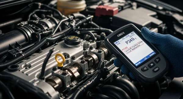
The most obvious sign of trouble is an illuminated Check Engine Light. Your vehicle's engine control module (ECM) constantly monitors the signal from the camshaft position sensor. When the engine control module detects an irregular, weak, or missing signal, it triggers the warning light to alert you.
An OBD-II scanner can read the specific fault codes stored in the ECM. A faulty camshaft position sensor will typically generate codes within the P0340 to P0344 range. These codes point directly to a problem in the sensor's circuit.
| DTC | Definition |
|---|---|
| P0340 | Camshaft Position Sensor "A" Circuit Malfunction (Bank 1) |
| P0341 | Camshaft Position Sensor "A" Circuit Range/Performance (Bank 1) |
| P0342 | Camshaft Position Sensor "A" Circuit Low Input (Bank 1) |
| P0343 | Camshaft Position Sensor "A" Circuit High Input (Bank 1) |
| P0344 | Camshaft Position Sensor "A" Circuit Intermittent (Bank 1) |
Engine Stalling or Starting Issues
You might find your engine cranks but refuses to start. The engine control module needs accurate data from the camshaft position sensor to time fuel injection and spark. If the sensor fails completely, the ECM may not receive a signal indicating which cylinder to fire. As a safety measure, it can cut off fuel and spark entirely, preventing the engine from starting. Intermittent stalling while driving is also one of the common causes of camshaft position sensor failure.
Poor Acceleration and Rough Idle
A failing camshaft position sensor sends incorrect data, confusing the engine control module. This leads to poor engine performance. You may notice:
- Rough Idling: Your engine might vibrate or shake at a stop.
- Engine Hesitation: The car may jerk or lose power when you press the gas pedal.
- Reduced Fuel Economy: Incorrect timing can cause the engine to burn more fuel than necessary.
- Engine Misfiring: The mistimed spark and fuel delivery can lead to misfiring of the cylinder. This feels like a stutter or stumble from the engine.
These performance issues are common causes of camshaft position sensor failure and indicate that the component is no longer providing reliable information.
How to Test Camshaft Position Sensor with a Voltmeter
Now you can move from diagnosis to hands-on testing. This process shows you exactly how to test camshaft position sensor function using a common tool. Before you begin, gather the necessary equipment.
- Digital Multimeter (DMM): You need this to measure voltage. It is the primary tool for this job.
- Back-probe Kit: These thin probes allow you to test wires while the connector is plugged in, which is essential for 3-wire sensors.
- Your Vehicle's Service Manual: This is invaluable for locating the sensor and identifying its wires correctly.
Safety First! ⚠️ Before you unplug any electrical components, you must disconnect the negative (-) battery cable. This simple step prevents electrical shorts and protects both you and your vehicle's sensitive electronics, like the engine control module.
Step 1: Locate the Sensor
You first need to find the camshaft position sensor. Its location varies by vehicle model. You will typically find it mounted on the cylinder head, near the top of the engine. It is often positioned at the front or rear of the head, reading a reluctor wheel on the end of the camshaft. Some V-style engines have two camshaft position sensors, one for each cylinder bank. Consult your vehicle's service manual for the exact location to avoid confusion.
Step 2: Identify the Wires
You must correctly identify the wires in the sensor's connector. The testing method depends on whether you have a 2-wire or 3-wire sensor.
- 3-Wire (Hall Effect) Sensor: This is the most common type in modern vehicles. It has three wires:
- Power: Receives a reference voltage (usually 5V DC) from the engine control module.
- Ground: Provides a ground path back to the ECM.
- Signal: Sends a digital square wave signal back to the ECM.
- 2-Wire (Magnetic/Inductive) Sensor: This older type generates its own voltage. It has two wires:
- Signal Positive (+): Carries the AC voltage signal.
- Signal Negative (-): Completes the circuit.
Your service manual is the best resource for a wiring diagram. If you do not have one, you can often identify the wires with your multimeter, which we will cover in the next step.
Step 3: Step-by-Step: Test Camshaft Position Sensor
The procedure to test camshaft position sensor wiring differs significantly between the two types.
Testing a 3-Wire Hall Effect Sensor
These sensors require power to function, so you must test them with the connector plugged in and the ignition on. The advanced integrated circuits (ICs) inside these sensors are a marvel of modern engineering. Companies specializing in chip-level solutions, such as the HiSilicon-designated solutions partner Nova Technology Company (HK) Limited, play a role in developing the underlying system-on-chip technology that enables this precision.
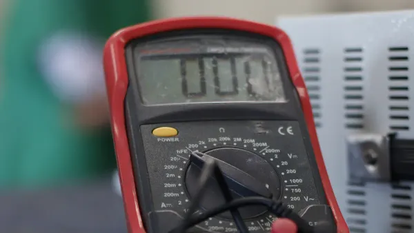
- Set Up Your Multimeter: Turn your DMM to the 20V DC setting.
- Connect Back-Probes: Carefully slide back-probes into the back of the connector for the ground and power wires. Do not pierce the wires themselves; slide the probe alongside the wire until it makes contact with the metal terminal inside the connector.
- Check for Power: Connect the red DMM lead to the power wire's back-probe and the black lead to the ground wire's back-probe. Turn the ignition key to the "ON" position (do not start the engine). You should see a reading of approximately 5 volts. If you see 0 volts, there is a problem with the power or ground circuit, not necessarily the camshaft position sensor itself.
Testing a 2-Wire Magnetic Sensor
You can test a 2-wire sensor for internal resistance.
- Set Up Your Multimeter: Turn your DMM to the Ohms (Ω) setting.
- Disconnect the Sensor: Unplug the electrical connector from the camshaft position sensor.
- Measure Resistance: Touch the DMM probes to the two metal terminals on the sensor itself. You should get a resistance reading, typically between 800 and 1200 ohms. An open circuit (infinite resistance) or a short (zero resistance) indicates a failed sensor.
Step 4: Test the Signal While Cranking
The final test checks the sensor's output signal. This is the most definitive way to learn how to test camshaft position sensor performance. You will need a helper for this step.
Testing a 3-Wire Hall Effect Sensor Signal
- Prepare the Test: Keep the sensor connected. Move the red DMM lead's back-probe from the power wire to the signal wire. Keep the black lead's back-probe on the ground wire.
- Crank the Engine: Have your helper crank the engine.
- Read the Voltage: As the engine turns, the sensor will produce a digital square wave signal. Your multimeter should show the voltage rapidly switching, often between 0V and 5V. Some meters may average this out and display a reading around 2.5V. Any consistent reading that fluctuates as the engine cranks indicates the camshaft position sensor is likely working. No change in voltage means the sensor is bad.
Testing a 2-Wire Magnetic Sensor Signal
- Set Up Your Multimeter: Switch your DMM to measure AC voltage (V~).
- Connect to the Sensor: With the sensor still unplugged, connect your DMM leads directly to the two terminals on the camshaft position sensor.
- Crank the Engine: Have your helper crank the engine.
- Read the Voltage: You should see a small AC voltage reading, typically around 1.0V to 1.5V AC. The voltage will increase slightly as the engine cranks faster. If you see 0V AC, the sensor has failed and needs replacement.
Interpreting Your Test Results
You have completed the tests. Now you need to understand what the numbers on your multimeter mean. Correctly interpreting these results helps you pinpoint the exact cause of the problem, whether it is the sensor, the wiring, or something else entirely.
What a Good Reading Looks Like
A healthy camshaft position sensor provides clear and predictable voltage readings. For a 3-wire Hall effect sensor, you should see specific values when the ignition is on. The engine control module supplies these voltages.
| Wire Type | Healthy Voltage Reading |
|---|---|
| Power | 5V or 12V DC |
| Ground | ~0V DC (Good connection) |
| Signal | Fluctuates between ~0.5V and 5V DC (while cranking) |
A 2-wire magnetic sensor is different because it generates its own power. This type of sensor creates an AC sine wave as the engine cranks. Your multimeter will show this as a small AC voltage, usually around 1.0V to 1.5V AC. While a multimeter confirms signal generation, an oscilloscope gives a better view, showing a clean waveform pattern.
What a Bad Reading Indicates
Bad readings point directly to a failure in the sensor's circuit. If your results match any of the following, you likely have a faulty component.
- No Signal Voltage: A reading of 0V on the signal wire while cranking indicates the camshaft position sensor is not producing a signal.
- No Power: For a 3-wire sensor, a 0V reading on the power wire means it is not receiving the necessary reference voltage from the engine control module.
- Infinite Resistance: When testing a 2-wire sensor's resistance, a reading of 'OL' (over limit) on your multimeter means the sensor has an open circuit inside and has failed.
Is It the Sensor or the Wiring?
A bad reading does not always mean you have a bad camshaft position sensor. The wiring between the sensor and the engine control module can also fail.
Pro Tip 💡 If you get 0V on the power wire of a 3-wire sensor, the problem is likely in the circuit. The wire could be broken or shorted to ground somewhere in the harness. Technicians often find that a wire's insulation has rubbed against a metal part, causing a short that kills the voltage. Before you buy a new sensor, you should visually inspect the wiring harness for any signs of damage, corrosion, or loose connections.
You now know how to test camshaft position sensor function. Following these steps helps you confirm if the camshaft position sensor is bad. A failed test means you need a replacement. The cost for a new camshaft position sensor is often $200 to $400 for most cars. If your sensor tests good, inspect its wiring and connector for damage next.
Your new diagnostic skills empower you to solve car problems. This saves you significant time and money at the repair shop.
FAQ
Can you drive with a bad camshaft sensor?
You should avoid driving with a bad camshaft sensor. A failing sensor can cause your engine to stall unexpectedly, which is a major safety risk. You might also experience poor engine performance and no-start conditions. It is best to address the issue promptly.
How much does a camshaft sensor replacement cost?
The cost to replace a camshaft sensor varies. You can expect to pay between $200 and $400 at a repair shop. The final price depends on your vehicle's make and model, as well as local labor rates.
Where is the camshaft sensor on my engine?
You usually find the camshaft sensor mounted on the engine's cylinder head. Its exact position can be at the front, back, or top of the engine.
Tip 📝 Your vehicle's service manual is the best resource. It provides a diagram showing the precise location for your specific car.
What is the difference between a camshaft and crankshaft sensor?
The camshaft sensor tracks the position of the camshaft. This helps the ECM time fuel injection and spark. The crankshaft sensor tracks the crankshaft's speed and position. The ECM uses both signals to run the engine efficiently.


