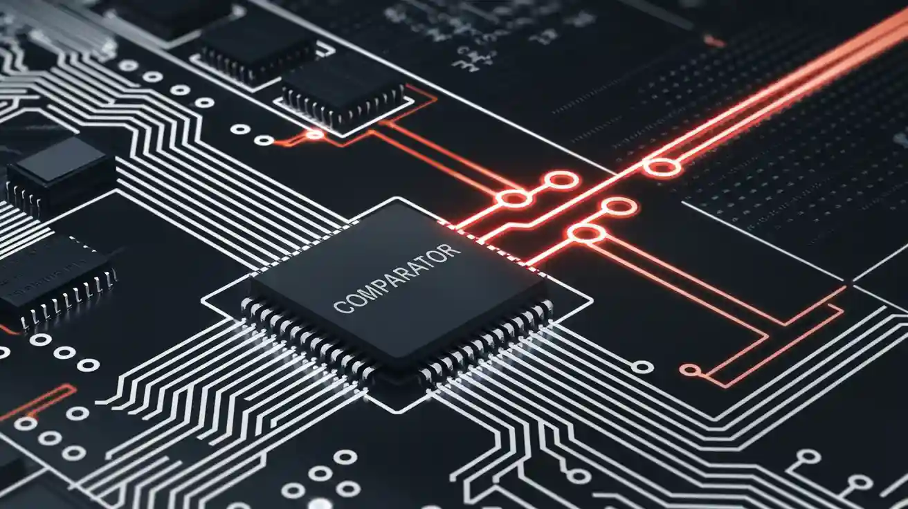
Comparator Integrated Circuits: Essential Components for Signal Processing and Threshold Detection
Comparator integrated circuits are important amplifiers. They compare two analog voltages. Then, they give a digital output. These ics help find when a signal passes a certain level. This protects sensitive electronics.
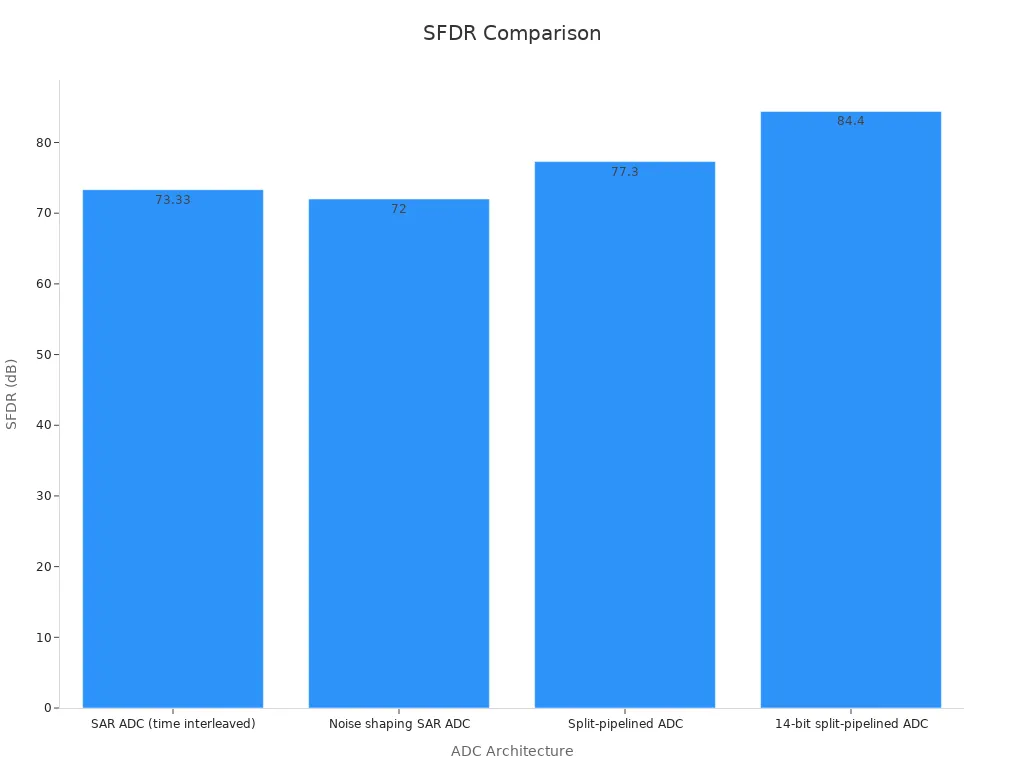
Comparator integrated circuits are important amplifiers. They compare two analog voltages. Then, they give a digital output. These ics help find when a signal passes a certain level. This protects sensitive electronics. It also helps make choices in signal processing. When a comparator sees a signal cross a set point, it changes its output. This helps turn analog signals into digital ones. Many amplifiers, like those in ADC designs, need comparators for correct work. The table below shows how different comparators help change analog signals to digital in amplifiers:
|
ADC Architecture |
Comparator Role |
ENOB (bits) |
SFDR (dB) |
SNR (dB) |
SNDR (dB) |
Sampling Rate (MS/s) |
Power Consumption (mW) |
Chip Area (mm²) |
Process Technology |
|---|---|---|---|---|---|---|---|---|---|
|
SAR ADC (time interleaved) |
Comparator-based SAR conversion |
11 |
73.33 |
N/A |
N/A |
90 |
0.806 (806 μW) |
0.03 |
65 nm CMOS |
|
Noise shaping SAR ADC |
Comparator with integrator for noise shaping |
10 |
72 |
N/A |
N/A |
90 |
0.806 |
0.03 |
65 nm CMOS |
|
Charge sharing SAR ADC |
Comparator in charge sharing DAC |
10.64 |
N/A |
70.06 |
65.82 |
20 |
N/A |
0.81 (1600×505 μm) |
130 nm CMOS |
|
Pipelined ADC (dynamic comparator) |
Dynamic comparator in pipelined stages |
N/A |
N/A |
61 |
66 |
50 |
31 |
N/A |
N/A |
|
Split-pipelined ADC |
Comparator in sub-stages and flash ADC |
N/A |
77.3 |
N/A |
66 |
N/A |
9 |
N/A |
N/A |
|
14-bit split-pipelined ADC |
Comparator in pipelined stages with calibration |
N/A |
84.4 |
N/A |
71.7 |
N/A |
32 |
N/A |
N/A |
Key Takeaways
-
Comparators check two voltages and give a digital output. They change analog signals into clear high or low signals. This helps make fast decisions.
-
Adding hysteresis to comparator circuits stops false switching from noise. This makes the outputs more steady and dependable.
-
Comparators are not like op-amps because they work without feedback. They also switch faster. This makes them good for digital signal processing and threshold detection.
-
There are different types of comparators for different jobs. Some are for low-power devices. Others are for fast communication systems. They help with things like battery monitoring and motor control.
-
Picking the right comparator means you must balance accuracy, speed, power use, and noise protection. This helps your electronic design work well for its job.
Definition and Structure
Comparator integrated circuits are very important in electronics today. These amplifiers look at two voltages and give a digital output. The main part of a comparator is a differential amplifier stage. This part has two inputs. One input is inverting, and the other is non-inverting. If the non-inverting input gets a higher voltage, the output goes high. If the inverting input is higher, the output goes low. This lets comparators change analog signals into digital signals.
A normal comparator circuit uses a high-gain differential amplifier. The output can be open-collector or push-pull. Open-collector outputs need a pull-up resistor. They can connect to different logic levels. Push-pull outputs give stronger drive and even waveforms. Many comparator ics have features like built-in reference voltages and adjustable hysteresis. These features help stop unwanted switching from noise.
The table below shows important technical details and features of comparator integrated circuits:
|
Specification / Feature |
Details / Performance Data |
|---|---|
|
Adjustable pins are there but often not used to make design simple and work better |
|
|
Operating Voltage |
Usually uses +5V supply (VCC+ at +5V, VCC- at ground) for steady work |
|
Output Characteristics |
Open collector output lets it work with logic levels |
|
Response Behavior |
Changes output when input voltage is compared to reference voltage |
|
Input Terminals |
Has both inverting and non-inverting inputs for comparing voltages |
|
Applications |
Used in signal conditioning, PWM motor control, voltage regulation, battery monitoring, motion detection, overcurrent protection |
|
Design Notes |
Accurate switching makes digital and analog interfacing work better |
Differential comparators use both NPN and PNP transistors in the input stage. This helps the device handle many input voltages. The output stage often uses emitter followers for full supply swing. Some popular comparator ics are LM339, LM393, and TLV3501. These devices switch fast and work well in many uses.
Tip: Adding hysteresis to a comparator circuit helps stop false switching from noise. Designers also use bypass capacitors and short input traces for better stability.
Comparator vs. Op-Amp
Many people mix up comparators and operational amplifiers. Both use differential amplifier stages, but they are made for different jobs. Comparators are made for fast switching and digital output. They work in open-loop mode and do not use feedback resistors. This makes them react quickly to small voltage changes.
Operational amplifiers, called op-amps, are general amplifiers. They make analog signals bigger and often use feedback for gain and stability. Op-amps are best for linear jobs, like audio amplifiers or filters. Comparators are electronic comparators. They compare two voltages and give a digital output.
Here are some main differences between comparators and op-amps:
-
Comparators work in open loop, but op-amps use feedback.
-
Comparators give digital outputs; op-amps give analog outputs.
-
Comparator ics are faster and have special output stages.
-
Comparators often have hysteresis and internal latches for better switching.
-
Op-amps are not made for fast changes or digital connections.
Differential comparators are needed in mixed-signal systems. They help with threshold detection, zero-crossing detection, and window comparison. Digital comparators and voltage comparators help make fast choices in analog-to-digital converters and protection circuits. Electronic comparators are also used in motion detection, battery monitoring, and overcurrent protection.
Note: Good layout, grounding, and signal routing are important for comparator circuits. These steps help stop oscillations and keep the circuit stable, especially in fast designs.
Working Principle
Input and Output Behavior
Comparators are important in electronics because they compare two voltages. They use a differential input stage to do this job. One input is called non-inverting, and the other is inverting. If the non-inverting input has more voltage than the inverting input, the output goes high. If the inverting input is higher, the output goes low. This quick change makes a clear digital signal from an analog difference.
The output of a comparator works like a switch. It moves between two steady voltage levels. These levels match the logic used in digital circuits. This lets comparators act as voltage-level detectors. Designers use comparators for voltage detection, signal detection, and level sensing. They can notice small voltage differences and give fast, steady digital outputs.
Tests show that devices like the LM339AN comparator switch output very fast. They do this when the input passes a set reference voltage. This makes comparators good as 1-bit analog-to-digital converters. In real life, like in power supply monitoring, comparators keep a steady binary output even if the input changes. Adding hysteresis helps stop unwanted switching from noise. This makes the output more stable.
Note: How fast a comparator responds depends on the input overdrive and output load. Fast comparators, like the LM339AN and LT1394, can switch in nanoseconds. This speed is needed for signal processing that needs quick choices.
Comparators are not like general amplifiers. They do not make signals bigger in a smooth way. Instead, they act as digital comparators. They give a clear high or low output after comparing input voltages. This is why they are needed in circuits that need fast and correct voltage comparison.
Threshold Detection
Threshold detection is a main job for comparators. Here, the comparator watches an input voltage and checks it against a set reference voltage. When the input crosses the reference, the output changes. This shows the exact time a signal passes a certain voltage. Engineers use this in many signal processing systems.
The threshold is the voltage where the comparator switches its output. Designers often add hysteresis to the circuit. Hysteresis makes two switching points: one for rising input and one for falling input. This stops the output from changing too much when the input is near the threshold, especially if there is noise. The Schmitt trigger is a common comparator circuit with hysteresis. Tests show that hysteresis helps block noise and keeps the output steady.
A comparator can work as a simple analog-to-digital converter. It turns an analog voltage into a digital signal. When the input goes above the threshold, the output goes high. When the input drops below the threshold, the output goes low. This lets comparators do voltage detection and signal processing right away.
The table below shows common numerical thresholds and error margins in comparator-based threshold detection:
|
Aspect |
Numerical Threshold / Value |
Error Margin / Variability |
Notes |
|---|---|---|---|
|
Forced-choice procedure threshold |
Stimulus level giving 0.707 chance of correct answer in 3I-3AFC |
Adaptive step sizes: 5 dB at first, then 1 dB near threshold |
Threshold is 0.561 quantile after guessing correction |
|
Reaction probability threshold (LT(RP)) |
Stimulus level causing reaction probability of 0.561 |
Usually 5-6 dB higher than forced-choice detection threshold |
Corrected for false alarms for accuracy |
|
Reaction time threshold (RQ) |
0.561 quantile of measured reaction time |
Close to reaction probability threshold after correction |
Assumes constant minimum reaction delay (RQmin) per person/session |
|
Correction factors |
Correction for guessing (forced-choice) and false alarms (reaction measures) |
Needed for good threshold estimates |
Day-to-day changes noticed |
|
Step size in adaptive procedure |
5 dB until 4th reversal, then 1 dB for last 8 reversals |
Gives finer detail near threshold |
Mean of last 4 reversals used as threshold estimate |
This data shows why accurate threshold detection matters and why error margins are important in real systems. Correction factors, like those for guessing and false alarms, help make sure threshold estimates are reliable.
Types of Comparators
There are many kinds of comparators. Each kind is good for different jobs in electronics. Engineers use analog comparators in cars, factories, and home devices. The table below shows how each comparator type helps different industries and uses.
|
Comparator Type |
Usage/Application Highlights |
Market/Usage Insights |
|---|---|---|
|
Analog Comparators |
Used in automotive electronics, consumer electronics, industrial automation |
Growth driven by electric/autonomous vehicles, smart devices, Industry 4.0 automation |
|
Micropower Comparators |
Low power consumption, used in battery-operated devices and medical electronics |
Rising demand due to energy efficiency needs |
|
High-Speed Comparators |
Fast response for high-frequency communication, radar, data acquisition |
Increasing importance in high-speed applications |
|
Product Type Segmentation |
Single-channel: simple circuits, low power; Dual-channel: simultaneous signal comparison; Quad-channel: complex, multi-signal applications; Others: niche, specialized |
Single-channel holds significant share; Quad-channel fastest growth; Others stable in defense/aerospace |
|
End-User Segments |
OEMs: major market portion integrating comparators in manufacturing; Aftermarket: replacement and maintenance |
OEM demand driven by automotive, industrial, healthcare, consumer electronics; Aftermarket grows with device lifespan |
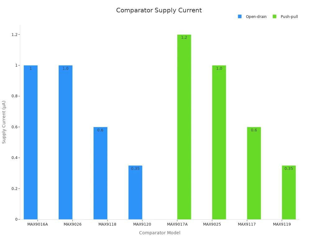
Open-Collector and Push-Pull
Open-collector comparators need a pull-up resistor on the output. This lets them work with different voltage levels and logic types. They are good for cars and tough places because they handle high voltages. Push-pull comparators have an output that is powered both ways. They switch faster and do not need a pull-up resistor. Push-pull types are best when you need quick switching and strong digital signals.
|
Comparator Model |
Output Stage Type |
Notes |
|
|---|---|---|---|
|
MAX9016A |
Open-drain |
1 |
Needs pull-up resistor; flexible level shifting |
|
MAX9017A |
Push-pull |
1.2 |
Faster switching; actively driven output |
|
MAX9119 |
Push-pull |
0.35 |
Lowest supply current in series |
|
MAX9120 |
Open-drain |
0.35 |
Same supply current as push-pull counterpart |
Open-collector outputs can handle higher voltages. Push-pull outputs are faster and make circuits easier.
High-Speed and Low-Power
High-speed comparators react fast to voltage changes. Engineers use them in radar, fast data, and communication. These comparators often use latch designs to work quickly. Low-power comparators use very little energy. They are good for battery gadgets and medical tools. Designers must pick between speed and saving power. Faster comparators can use more power and make more noise. Careful design helps save power but keeps speed.
|
Parameter |
Value |
Notes |
|---|---|---|
|
Power Consumption |
At 1 V supply, worst-case scenario |
|
|
Propagation Delay |
44.55 ps |
Measured under PVT variations |
|
Input-referred Offset |
2.47 mV |
Optimized via cascode NMOS transistor design |
|
Energy per Operation |
11 fJ |
At 10 GHz sample frequency |
|
Active Area |
97.04 μm² |
Compact layout suitable for high-speed applications |
Window and Zero-Crossing
Window comparators check if a voltage stays inside a set range. They use two analog comparators to watch the top and bottom limits. These circuits help with battery checks and stopping too much voltage. Zero crossing detectors find when a voltage goes through zero. Engineers use them in phase-locked loops, checking waves, and motor control. Zero crossing detectors give exact timing for switching and signals. Many analog and electronic comparators work as zero crossing detectors in today’s circuits.
Zero crossing detectors are important in signal processing. They help with timing and finding the phase of signals.
Comparators in Applications
Signal Processing
Comparators are very important in signal processing. They help change analog voltages into digital signals. This lets systems make quick and correct choices. Engineers use analog comparators for signal detection and level sensing. They also use them as zero crossing detectors. These circuits can tell when a signal passes a certain voltage. This is needed for timing and changing data.
A high-speed comparator can switch very fast, in just nanoseconds. This fast speed helps with real-time analog-to-digital conversion. It is used in things like 5G and radar. For example, a 40-Gb/s CMOS clocked comparator can have a bit error rate less than 10^-12 at a 10 GHz toggle rate. This means it works well for high-speed signal processing in new electronics.
|
Application Area |
Comparator Type |
Quantified Example / Performance Metric |
Impact / Use Case Description |
|---|---|---|---|
|
High-Speed Signal Processing |
High-Speed Comparator |
Nanosecond switching speeds (ns-level response time) |
Enables real-time analog-to-digital conversion at GHz rates for ADCs and 5G communications. |
|
Portable Devices |
Low-Power Comparator |
Minimal current draw, low supply voltage (e.g., 1.8V–5V) |
Extends battery life in IoT sensors and wearable devices by reducing power consumption. |
Voltage Monitoring
Comparators are needed for voltage monitoring in batteries and power supplies. They also help in temperature sensors. They compare input voltages to a reference voltage. When the voltage goes past a safe limit, they send a signal. This helps protect circuits from too much or too little voltage.
A window comparator checks if a voltage stays between two set levels. For example, it can watch if a battery stays between 3.5V and 4.2V. In adaptive power control, a variable threshold comparator can lower net power by 12.39% and leakage by 7.96%. The LM339AN comparator is fast and easy to use. It is good for voltage monitoring. It uses very little current, sometimes less than 2µA. It can work with supply voltages as low as 1.0V.
|
Application Area |
Comparator Role |
Numerical Evidence |
Additional Details |
|---|---|---|---|
|
Voltage Monitoring in APC |
Variable threshold comparator |
12.39% net power reduction; 7.96% leakage reduction |
5% area overhead; 1.08% power overhead; monitors VDDV node |
|
Battery Voltage Monitoring |
Window Comparator |
Output high when voltage is between 3.5V and 4.2V |
Ensures safe battery charging by detecting voltage within a specific range. |
-
Simple circuit design and fast response make comparators good for voltage detection.
-
How reliable they are depends on the parts and design.
-
Accuracy can be affected by offset and hysteresis, so these must be controlled.
Noise Immunity and Hysteresis
Noise can make comparator circuits switch by mistake. This happens when input voltages are close to the threshold. Engineers add hysteresis to help stop this problem. Hysteresis makes two switching points. One is for rising voltage and one is for falling voltage. This stops the output from changing too quickly because of small noise spikes.
For example, a 74LS14 Schmitt trigger uses a positive threshold of 1.6V and a negative threshold of 0.8V. The difference between them is called hysteresis voltage, which is 0.8V. This gap stops the output from chattering and keeps the signal steady. In real designs, resistors set the hysteresis voltage. A TLC39 comparator with a 22.6 mV hysteresis voltage can block noise near the threshold. But it also makes a small dead zone.
Hysteresis in comparators works like a thermostat’s "backlash." It stops fast switching and keeps voltage monitoring circuits steady, even when there is noise.
Selecting a Comparator
Key Parameters
Engineers pick comparators by checking some main things. These amplifiers must compare voltages very accurately. Input offset voltage is one important thing. It tells how much the input voltages can be different before the output changes. If the offset is lower, the accuracy is better. Response time is another key thing. A fast response lets the comparator catch quick changes in signals. Power use is important for battery devices. Designers want amplifiers that save energy but still work well. Common-mode rejection ratio helps block unwanted voltages on both inputs. This makes the device more accurate in noisy places.
|
Parameter |
Value |
Description |
|---|---|---|
|
Input Offset Voltage (Vos) |
Small voltage difference needed for output to switch; affects precision. |
|
|
Response Time |
165 ns–1.3 μs |
Time to change output after input changes; important for fast signal detection. |
|
Input Bias Current |
250–300 nA |
Current entering input terminals; impacts signal integrity. |
|
Output Current per Channel |
18–50 mA |
Maximum current each channel can deliver. |
|
Supply Voltage Range |
±1.75 V to 15 V |
Range of voltages for proper operation. |
Design Considerations
Designers have to think about many things when picking amplifiers.
-
They check both dynamic and static power use to save energy.
-
They look at how much energy is used each time the comparator switches.
-
Cost depends on how many chips are good from each wafer. More good chips mean lower price.
-
Analog IC design needs careful transistor size and bias. This gives the right gain and speed.
-
Designers pick ASICs for special jobs and SoCs for flexible uses.
Good design choices help make circuits more accurate, use less power, and find voltages reliably.
Advantages and Limitations
Comparators have lots of good points in electronics today. They switch fast and work well with digital logic. Their accuracy helps find small voltage changes. But these amplifiers can be bothered by noise. Designers add hysteresis or use special layouts to stop false switching. Power use and careful testing setups can also be a problem sometimes.
|
Performance Parameter |
Description & Impact |
|---|---|
|
Fast switching, but affected by internal capacitance and resistance. |
|
|
Supply Voltage Range |
Wide range supports many applications, but some amplifiers need higher voltages. |
|
Input Common-Mode Range |
Inputs must stay within this range for proper operation. |
|
Hysteresis Behavior |
Built-in or external hysteresis improves stability and precision. |
|
Output Stage Configuration |
Push-pull or open-drain outputs affect logic compatibility and current sourcing. |
Designers should always pick comparator features that fit their signal processing needs for the best results.
Comparator integrated circuits are very important in today’s electronics. They help devices handle signals and find when levels change. They also keep delicate parts safe from harm. The market for comparators is getting bigger. It was $1.86 billion in 2023. Experts think it will grow to $3.0 billion by 2032.
-
More businesses use comparators in cars, hospitals, and factories.
-
Companies spend money on research and work together to make better products.
Engineers and students can use comparators to make their projects work better and be more dependable.
FAQ
What does a comparator integrated circuit do?
A comparator IC looks at two voltages. It gives a digital output to show which one is higher. This helps a device know when a signal passes a certain level.
How is a comparator different from an op-amp?
A comparator changes its output fast between high and low. An op-amp makes signals stronger and uses feedback. Comparators work with digital signals. Op-amps are used for analog signals.
Why do engineers add hysteresis to comparator circuits?
Hysteresis stops the output from switching by mistake. It makes two points for switching, so the output stays steady even if the input has noise.
Where do people use comparator ICs?
-
Checking battery voltage
-
Signal processing
-
Overcurrent protection
-
Motor control
These ICs help many devices stay safe and make quick choices.