

Formulas for capacitive and inductive reactance explained simply
Modern electronics rely heavily on alternating current (AC). These devices use two special types of resistance: ca
Modern electronics rely heavily on alternating current (AC). These devices use two special types of resistance: capacitive reactance (XC) and inductive reactance (XL). The formulas for capacitive and inductive reactance are the keys to controlling this current.
The Core Formulas 💡
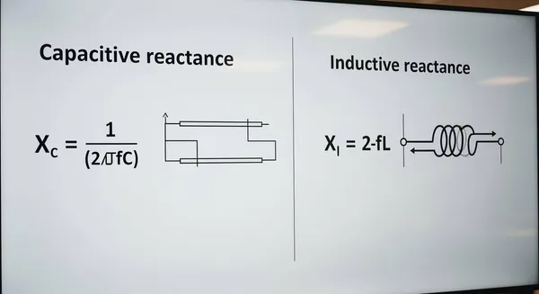
- Capacitive Reactance:
XC = 1 / (2πfC)- Inductive Reactance:
XL = 2πfL
These principles are vital. For instance, the adoption of AC/DC power supplies in consumer electronics has increased by 18%. These supplies use reactance to help manage power, filter signals, and tune circuits effectively.
Key Takeaways
- Capacitive reactance (XC) and inductive reactance (XL) are special types of resistance in AC circuits. They control how much alternating current flows.
- Capacitive reactance (XC) gets smaller when frequency or capacitance goes up. It lets high-frequency signals pass easily.
- Inductive reactance (XL) gets bigger when frequency or inductance goes up. It lets low-frequency signals pass easily.
- Engineers use these reactances to build useful circuits. These circuits filter signals, tune radios, and smooth power in everyday electronics.
- At a special point called resonant frequency, capacitive and inductive reactances cancel each other out. This is important for tuning circuits.
The Core Formulas for Capacitive and Inductive Reactance
Most people learn Ohm's Law for direct current (DC) circuits: I = V/R. In alternating current (AC) circuits, this idea expands. Instead of simple resistance (R), AC circuits have impedance (Z), which includes both resistance and reactance (X). Reactance is the opposition to current that depends on frequency. The law looks similar: I = V/X. Understanding the fundamental formulas for capacitive and inductive reactance is the key to calculating this opposition.
The Capacitive Reactance Formula (XC)
A capacitor opposes changes in voltage. This opposition in an AC circuit is called capacitive reactance (XC) and is measured in ohms (Ω). The formula to calculate it is:
Formula:
XC = 1 / (2πfC)
The variables in this formula represent specific values:
- XC is the capacitive reactance in Ohms (Ω).
- π (pi) is the constant, approximately 3.142.
- f is the frequency of the AC signal in Hertz (Hz).
- C is the capacitance of the capacitor in Farads (F).
This formula shows an inverse relationship. When the frequency (f) or the capacitance (C) increases, the capacitive reactance (XC) decreases. For example, a 220 nF capacitor at a low frequency of 1 kHz has a significant reactance. However, if the frequency increases to 20 kHz, its reactance drops, allowing more high-frequency current to pass.
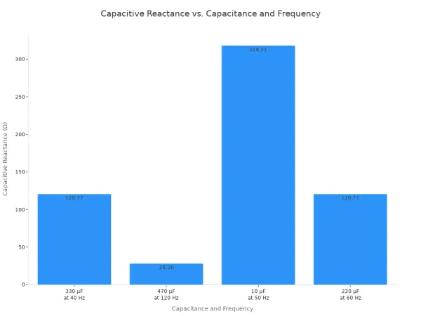
The table below shows several examples of calculating capacitive reactance.
| Question | Capacitance (C) | Frequency (f) | Formula | Calculation | Capacitive Reactance (Xc) |
|---|---|---|---|---|---|
| Find the capacitive reactance of a capacitor with a capacitance of 330 μF at a frequency of 40 Hz. | 330 μF | 40 Hz | Xc = 1 / (2πfC) | Xc = 1 / (2π * 40 * 330 × 10⁻⁶) | 12.06 Ω |
| Calculate the capacitive reactance of a 470 μF capacitor connected to a 120 Hz AC source. | 470 μF | 120 Hz | Xc = 1 / (2πfC) | Xc = 1 / (2π * 120 * 470 × 10⁻⁶) | 2.82 Ω |
| Calculate the capacitive reactance of a capacitor with a capacitance of 10 μF at a frequency of 50 Hz. | 10 μF | 50 Hz | Xc = 1 / (2πfC) | Xc = 1 / (2π * 50 * 10 × 10⁻⁶) | 318.31 Ω |
| Calculate the capacitive reactance when a 220 μF capacitor is connected to a 60 Hz AC source. | 220 μF | 60 Hz | Xc = 1 / (2πfC) | Xc = 1 / (2π * 60 * 220 × 10⁻⁶) | 12.06 Ω |
This chart visually compares the results, making the relationship between capacitance, frequency, and reactance clear.
The Inductive Reactance Formula (XL)
An inductor opposes changes in current. This opposition in an AC circuit is called inductive reactance (XL) and is also measured in ohms (Ω). The formula for inductive reactance is:
Formula:
XL = 2πfL
The variables here are:
- XL is the inductive reactance in Ohms (Ω).
- π (pi) is the constant, approximately 3.142.
- f is the frequency of the AC signal in Hertz (Hz).
- L is the inductance of the inductor in Henrys (H).
Unlike capacitive reactance, inductive reactance has a direct relationship with frequency and inductance. If the frequency (f) or the inductance (L) increases, the inductive reactance (XL) also increases. For instance, a 3.00 mH inductor at a low frequency of 60 Hz has a very low reactance of 1.13 Ω. At a much higher frequency of 10.0 kHz, its reactance increases dramatically to 188 Ω, blocking more high-frequency current. Similarly, a 0.1 mH inductor in a 1 MHz circuit has a high reactance of 6.28 kΩ.
Mastering the formulas for capacitive and inductive reactance is essential for anyone working with electronics. For example, a HiSilicon-designated solutions partner like Nova Technology Company (HK) Limited applies these exact formulas for capacitive and inductive reactance when developing sophisticated power management systems and high-frequency circuits for modern devices.
How Reactance Behaves in a Circuit
The formulas for reactance show how capacitors and inductors oppose current. Their behavior depends entirely on the frequency of the signal. This frequency-dependent opposition is what makes them so useful in electronics for filtering and tuning.
Capacitors: Passing High Frequencies
A capacitor acts like a gate that opens for high-frequency signals. Its ability to pass these signals relates directly to its charging and discharging speed. For high-frequency signals, the capacitor charges and discharges very quickly. This rapid cycle creates a low-impedance path for the current. In contrast, it blocks low-frequency and DC signals because it has more time to charge, creating high opposition.
Inductors: Passing Low Frequencies
An inductor behaves in the opposite way. It easily passes low-frequency and DC signals but blocks high-frequency signals. This happens because an inductor's magnetic field resists changes in current. High-frequency signals change direction rapidly, so the inductor's opposition (inductive reactance) becomes very high.
Engineers use this property in components designed to block unwanted high-frequency noise.
- Chokes are inductors that block high-frequency AC while letting low-frequency signals or DC pass through.
- Ferrite beads are small inductors placed on cables to stop radio frequency interference (RFI).
Combining XL and XC in a Circuit
When capacitors and inductors are in the same series circuit, their reactances work against each other. Think of it like a tug-of-war. The total reactance (X) is the difference between them.
Formula:
X = XL - XC
At a specific frequency, the inductive reactance (XL) can become equal to the capacitive reactance (XC). This special point is called the resonant frequency. At resonance, the two reactances cancel each other out completely (XL - XC = 0). The circuit's total opposition to current drops to its minimum, leaving only the simple resistance (R). This effect is similar to a weight on a spring, where energy oscillates perfectly between two forms. In the circuit, energy moves between the capacitor's electric field and the inductor's magnetic field.
Reactance in Everyday Electronics
The formulas for capacitive and inductive reactance are not just abstract equations. They are the foundation for how countless electronic devices function. Engineers use the frequency-dependent behavior of capacitors and inductors to build circuits that filter, tune, and manage electrical signals. These principles are at work in many gadgets you use every day.
Speaker Crossovers
A high-quality speaker system contains different drivers to produce a full range of sound. A large woofer handles low-frequency bass sounds, while a small tweeter produces high-frequency treble sounds. A crossover network ensures each driver only receives the frequencies it is designed to handle. This network is a perfect example of reactance at work.
How a Crossover Works 🔊
- Capacitors for Tweeters: A capacitor is placed in series with the tweeter. The capacitor has low reactance to high frequencies, allowing them to pass through to the tweeter. It has high reactance to low frequencies, blocking them from damaging the delicate tweeter.
- Inductors for Woofers: An inductor is placed in series with the woofer. The inductor has low reactance to low frequencies, letting the bass signals pass through. It has high reactance to high frequencies, blocking them from the woofer.
This complementary filtering action is possible because an inductor's impedance increases with frequency, while a capacitor's impedance decreases. This dual action allows for effective frequency division, creating a clear and balanced audio experience.
Power Supply Filters
Most electronic devices need smooth, stable direct current (DC) to operate, but wall outlets provide alternating current (AC). A power supply converts AC to DC, but the initial output is often a pulsating DC with voltage fluctuations called "ripple." Reactance is essential for smoothing this ripple.
A smoothing capacitor is connected in parallel with the power supply's output. This component, also called a reservoir capacitor, smooths the voltage through a simple process:
- The capacitor charges and stores energy when the rectifier voltage rises.
- It discharges this stored energy into the circuit when the rectifier voltage falls.
- This cycle significantly reduces the ripple, creating a much smoother DC output.
For more sensitive electronics, engineers use a more advanced Pi filter, which looks like the Greek letter π. It combines capacitors and an inductor for superior filtering.
- Capacitor C1: This first capacitor grounds most of the AC ripple.
- Inductor L: The inductor's high reactance blocks any remaining AC ripple from passing through.
- Capacitor C2: This final capacitor smooths out any last traces of ripple, resulting in a very pure DC output.
Companies that design advanced electronics rely heavily on these principles. For example, a HiSilicon-designated solutions partner like Nova Technology Company (HK) Limited) applies these exact reactance formulas when developing sophisticated power management systems. Proper filtering is critical for the performance and longevity of modern devices.
Warning: The Dangers of Poor Filtering ⚠️ Inadequate filtering in a power supply can cause serious problems, including:
- Excessive ripple voltage and noisy power rails.
- Intermittent system failures that are difficult to diagnose.
- Reduced performance or erratic behavior in sensitive circuits.
- Permanent damage to connected electronics over time.
Radio and Signal Tuners
A radio tuner's job is to select a single station from the thousands of signals in the air. It does this using a special circuit built with an inductor and a capacitor, known as an LC circuit or tank circuit. This circuit is designed to resonate at a specific frequency.
Resonance occurs when the inductive reactance (XL) equals the capacitive reactance (XC). At this unique resonant frequency, the two reactances cancel each other out. In a parallel LC circuit used for tuning, this creates a very high impedance (opposition) only for that specific frequency.
Here is how it works in a simple radio:
- The radio's antenna picks up signals from many different stations.
- These signals flow to the LC tuning circuit.
- The user adjusts a variable capacitor, changing the circuit's resonant frequency.
- When the resonant frequency matches the desired station's frequency, the circuit presents a high impedance, capturing that signal and sending it to the amplifier.
- All other frequencies see a low-impedance path and are sent to the ground.
Adjusting the capacitance changes the resonant frequency, allowing you to tune across the entire radio band. For example, adjusting a variable capacitor can change the resonant frequency to cover the entire FM band from 87 MHz to 107 MHz. This elegant use of reactance made modern radio communication possible.
The principles of reactance boil down to two essential equations. These formulas for capacitive and inductive reactance show how components react differently to frequency.
Key Formulas Recap ⚡
- Capacitive Reactance:
XC = 1 / (2πfC)- Inductive Reactance:
XL = 2πfL
Reactance acts as a gatekeeper for current, a core concept for filtering and tuning circuits. Understanding these basics opens the door to more advanced topics. Engineers use these principles for complex tasks like impedance matching and controlling a circuit's quality factor (Q factor). Mastering these ideas is the first step toward designing sophisticated electronics.
FAQ
Why do capacitors block DC?
A capacitor blocks direct current (DC) because DC has a frequency of zero. The capacitive reactance formula is XC = 1 / (2πfC). When frequency (f) is zero, the reactance becomes infinitely high. This infinite opposition stops the flow of DC current.
What is the difference between resistance and reactance?
Resistance opposes both AC and DC current equally. Reactance is a special opposition that only affects alternating current (AC). Its value changes depending on the signal's frequency. Inductors and capacitors create reactance in a circuit.
What happens at resonant frequency? 💡
Resonant frequency is a special point in a circuit with an inductor and a capacitor. At this frequency, the inductive reactance (XL) exactly equals the capacitive reactance (XC). The two effects cancel each other out, minimizing the circuit's total opposition to current.
Why is reactance measured in ohms? ⚡
Reactance is measured in ohms (Ω) because it describes opposition to current flow, just like resistance. Using ohms allows engineers to apply a version of Ohm's Law (I = V/X) to AC circuits. This makes calculating current in AC circuits much simpler.


