

Hands-On 555 Timer Chip Projects for Electronics Learners
Curious about practical 555 timer chip projects you can actually build? You’re in the right place! The 555 timer stands out
Curious about practical 555 timer chip projects you can actually build? You’re in the right place! The 555 timer stands out as one of the most versatile parts in electronics projects, especially for any beginner. You can use a breadboard and follow clear steps to explore real hands-on application. Check out these popular 555 timer chip projects:
- LED blinking light circuit
- Flashing lamp for decoration
- Smart fan with motion detection
- Simple rain water alarm
- Easy battery charger
Plenty of guides walk you through every step, making each project fun and easy to understand.
Key Takeaways
- The 555 timer chip is a simple, affordable, and versatile component ideal for beginners to learn about timing and pulses without programming.
- Using a breadboard with the 555 timer lets you build circuits easily and test different setups in astable or monostable modes for blinking lights, timers, and sound.
- Beginner projects like LED flashers, vehicle light circuits, audio tone generators, and motion detectors help you understand how components work together in real circuits.
- Innovative projects such as PWM LED dimmers and one-shot timers show how to control brightness and timing precisely using the 555 timer.
- Following practical tips and avoiding common mistakes ensures your circuits work well and stay safe, boosting your confidence and skills in electronics.
555 Timer Basics
What Is the 555 Timer Chip?
You might wonder why the 555 timer shows up in so many beginner projects. This small chip, invented in 1971 by Hans Camenzind, changed electronics forever. It’s famous for being simple, affordable, and super flexible. You can find the 555 timer in toys, alarms, and even spacecraft! Many teachers and hobbyists use it to help you learn about timing, pulses, and oscillators. The 555 timer lets you build real circuits without needing to know programming.
Here’s a quick look at what makes the 555 timer so great for beginners:
| Feature | Explanation |
|---|---|
| Adjustable Timing | You can set timing intervals with resistors and capacitors. |
| Wide Supply Voltage | Works with many power sources (4.5V to 15V). |
| High Output Current | Drives LEDs and small motors directly. |
| Ease of Use | Simple to connect and use on a breadboard. |
| Versatile Operating Modes | Supports different timing and switching tasks. |
| Internal Structure | Has comparators and flip-flops for precise timing. |
Breadboard Using 555 Timer IC
If you want to start building, a breadboard using 555 timer ic is your best friend. You don’t need to solder anything. Just plug the 555 timer into the breadboard, add a few wires, resistors, and capacitors, and you’re ready to go. Most beginner projects use the breadboard using 555 timer ic in two main ways: astable and monostable modes. You can make an LED blink or create a timer that turns something on for a set time. The breadboard using 555 timer ic setup helps you see how changing parts changes the timing. This hands-on approach makes learning electronics fun and easy.
Tip: Always double-check your pin connections on the breadboard. The 555 timer has eight pins, and each one has a special job!
Modes: Monostable and Astable
The 555 timer works in two main modes. In monostable mode, it acts like a one-shot timer. When you press a button, the output goes high for a set time, then returns low. This is perfect for making a simple timer or delay. In astable mode, the 555 timer keeps switching its output on and off, creating a steady pulse. This is how you make things like blinking LEDs or sound generators.
| Aspect | Monostable Mode | Astable Mode |
|---|---|---|
| Basic Operation | One timed pulse when triggered | Continuous square waves |
| Trigger | Needs a button or signal | Runs on its own |
| Use | Timers, alarms | Flashers, tone generators |
You can switch between these modes by changing how you connect the resistors and capacitors. Try both to see which fits your project best!
Beginner 555 Timer Chip Projects
Ready to get your hands on some real 555 timer chip projects? These beginner-friendly builds will help you understand timing, pulse generation, and basic circuit design. You’ll use a breadboard, simple components, and your curiosity. Let’s dive in!
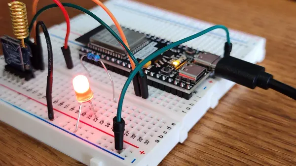
LED Flasher
You can start with the classic LED flasher. This is one of the most popular 555 timer projects for beginners. You’ll see two LEDs blink on and off, showing you how the 555 timer creates pulses.
What You Need:
| Component | Value/Description | Quantity |
|---|---|---|
| 555 Timer IC | Main IC for timing and oscillation | 1 |
| LEDs | Any color | 2 |
| Capacitor | 1µF or 10µF, 16V electrolytic | 1 |
| Resistors | 330Ω, 1kΩ, 10kΩ, 100kΩ | 1 each |
| Battery | 9V | 1 |
| Breadboard | For assembly | 1 |
| Jumper Wires | For connections | Several |
How to Build:
- Place the 555 timer in the breadboard.
- Connect pin 8 to power and pin 1 to ground.
- Tie pin 4 to VCC to prevent unwanted resets.
- Connect pins 2 and 6 together.
- Add the capacitor between pin 6 and ground.
- Place resistors between pins 7, 8, and 6 as shown in most 555 timer chip project diagrams.
- Connect LEDs to pin 3 (output) with current-limiting resistors.
- Attach the battery and watch the LEDs start flashing!
The flashing frequency usually ranges from 0.1 Hz to 5 Hz. You can change the speed by swapping out the capacitor or resistors.
This project helps you see how changing resistor or capacitor values affects the blinking rate. You’ll learn about timing circuits and how the 555 timer controls output.
Vehicle Light Circuit
Want to make your own police car lights? The vehicle light circuit uses the 555 timer and a decade counter to create cool flashing patterns. This is a fun way to explore more advanced 555 timer projects.
What You Need:
- 555 Timer IC
- CD4017 Decade Counter IC
- LEDs (red and blue work best)
- Resistors (470Ω, 1kΩ)
- Capacitors (1µF, 10µF)
- Transistors (for switching LED clusters)
- Breadboard and jumper wires
- 9V or 12V battery
How to Build:
- Set up the 555 timer in astable mode to generate pulses.
- Connect the output (pin 3) to the CD4017 counter.
- Arrange LEDs in clusters and connect them to the counter outputs with resistors.
- Use transistors to switch between LED clusters.
- Adjust the 555 timer frequency to control the flashing speed.
- Double-check all connections, especially LED polarity and resistor values.
- Power up and enjoy the alternating flashing effect!
Always use current-limiting resistors with LEDs and keep your supply voltage between 5V and 15V to protect your components.
This project teaches you about sequencing, pulse generation, and safe circuit design. You’ll also practice troubleshooting if the LEDs don’t flash as expected.
Audio Tone Generator
You can turn the 555 timer into a simple sound machine! The audio tone generator is a favorite among 555 timer chip projects. It creates beeps and buzzes you can hear with a small speaker.
What You Need:
- 555 Timer IC
- Resistors (1kΩ, 10kΩ, 100kΩ)
- Capacitor (0.01µF to 10µF)
- Small speaker or buzzer
- Breadboard and wires
- 9V battery
How to Build:
- Place the 555 timer on your breadboard.
- Connect pins 2 and 6 together.
- Add the timing resistor and capacitor between pins 6, 7, and ground.
- Connect the speaker to pin 3 (output) through a 100Ω resistor.
- Power the circuit and listen for the tone.
You can adjust the pitch by changing the resistor or capacitor values. The 555 timer can generate frequencies from 1 Hz up to 15 kHz, which covers most sounds you can hear. This project helps you understand how timing circuits create audio signals.
Motion Detector
If you want to try something a bit more advanced, build a motion detector. This project uses the 555 timer to control a relay when it senses movement.
What You Need:
- 555 Timer IC
- IR sensor module
- Resistors (100kΩ, 1kΩ)
- Capacitor (1µF)
- NPN and PNP transistors
- Relay with driver circuit
- Diodes (for relay protection)
- LED with resistor
- DC power jack
- Breadboard and wires
How to Build:
- Connect pins 2 and 6 of the 555 timer together.
- Tie pins 4 and 8 to power.
- Use a voltage divider and capacitor to set the timing.
- Connect the IR sensor to the base of the PNP transistor.
- Use the NPN transistor to drive the relay from the 555 timer output.
- Add an LED to show when motion is detected.
- Power the circuit and test by moving your hand in front of the sensor.
This project shows you how the 555 timer can work with sensors and relays. You’ll learn about input-output relationships and how to control devices with timing circuits.
Sound-Operated Timer
Ever wanted a circuit that reacts to a clap or loud noise? The sound-operated timer uses the 555 timer to turn something on for a set time after it hears a sound.
How It Works: When the microphone picks up a sound, it sends a pulse to the trigger pin (pin 2) of the 555 timer. The output (pin 3) goes high, turning on an LED or buzzer for a set delay. The timing depends on the resistor and capacitor values you choose.
What You Need:
- 555 Timer IC
- Microphone or sound sensor
- Resistors (10kΩ, 100kΩ)
- Capacitor (1µF)
- LED or buzzer
- Breadboard and wires
- 9V battery
How to Build:
- Connect the microphone to the trigger pin of the 555 timer.
- Set up the timing resistor and capacitor between pins 6, 7, and ground.
- Attach the output device (LED or buzzer) to pin 3.
- Power the circuit and make a loud sound to trigger the timer.
You’ll see how the 555 timer responds to input signals and creates a timed output. This project is a great way to learn about monostable mode and timing control.
Building these 555 timer chip projects helps you develop hands-on skills, understand how components interact, and boost your problem-solving abilities. You’ll also get ready for more advanced electronics projects like a touch on-off sensor switch circuit, water level alert, or even a latching touch sensitive alarm circuit.
Innovative 555 Timer Projects
Ready to level up your skills? Let’s look at some creative 555 timer projects that help you think like an engineer. When you experiment with different circuit parts, you see how small changes make a big difference. You can use both astable and monostable modes to control pulses, timing, and even brightness.
PWM LED Dimming
Have you ever wanted to control how bright your LED shines? You can build a led dimmer and dc motor speed controller circuit using the 555 timer in astable mode. This setup creates a special signal called PWM (pulse-width modulation). By turning a knob (potentiometer), you change how long the LED stays on or off. This is called the duty cycle. A higher duty cycle makes the LED brighter. A lower duty cycle dims it. You can also use this idea for a pwm motor controller or motor control circuit.
Tip: PWM lets you dim LEDs or control motor speed without wasting energy. It’s a smart way to make your circuits more efficient and extend the life of your parts.
Here’s a quick look at some innovative uses for the 555 timer:
| Project Type | Function/Use Case | Innovation Aspect for Beginners |
|---|---|---|
| LED Dimmer Circuit | Adjust brightness of LEDs | Uses 555 timer with transistor for power control |
| Buck Regulator for LED Dimmers | Controls LED brightness and motor speed | Combines 555 timer with MOSFET for power regulation |
| DC-DC Boost Converter | Increases voltage output | Uses 555 timer in switch mode power supply design |
| PWM Motor Controller | Controls speed of DC motors | Shows how pulse width changes affect motor speed |
Variable Audio Oscillator
You can make cool sounds by building a variable audio oscillator with the 555 timer. Change the resistors or capacitor, and you change the pitch. Try swapping out different parts and listen to the new tones. The main parts you adjust are R1, R2, and C. The formula for frequency is:
Frequency = 1.44 / [(R1 + 2×R2) × C]
This project helps you see how timing and frequency work together. You can even use the control voltage pin for fine-tuning. This hands-on approach helps you understand how a pwm motor controller works, too.
One-Shot Timer
Need a circuit that turns something on for a set time, then off? The one-shot timer uses the 555 timer in monostable mode. Press a button, and the output stays on for a delay you set with a resistor and capacitor. This is perfect for an adjustable auto on off delay timer circuit. Just remember, the timing accuracy depends on your parts. Most circuits have about 15% error because of the capacitor and resistor tolerances. For short delays, the 555 timer works great!
Try using a one-shot timer to control a light or buzzer for a few seconds after you press a button.
Tips and Troubleshooting
Common Mistakes
You might run into a few bumps when building circuits. Here are some mistakes beginners often make and how you can avoid them:
- Using very high-value capacitors or resistors for long delays. This can cause unreliable timing because the capacitor may not charge fully.
- Connecting a PNP transistor directly to the output. This setup can keep the transistor on and draw too much current. Try using an NPN transistor driver instead.
- Leaving the reset pin (pin 4) floating. This can cause random resets. Always connect it to the positive supply.
- Making wiring errors or using a non-standard layout. Stick to standard layouts for easier troubleshooting.
- Forgetting a small capacitor on pin 5. This can make your circuit less stable.
- Using electrolytic capacitors where they do not fit. Choose the right type for timing.
- Missing proper power or ground connections. Double-check these to keep your circuit running smoothly.
Tip: If your circuit does not work, check each connection and component value first.
Practical Tips
You can make your breadboard projects more reliable with a few simple habits:
- Double-check all connections, especially power and ground.
- Use IC sockets for chips to prevent damage from repeated insertions.
- Keep your wiring neat. Color-code jumper wires—red for power, black for ground.
- Avoid overloading the breadboard. Keep current below 1A and voltage below 24V.
- Label wires and components in complex builds.
- Test with a multimeter to find loose wires or misplaced parts.
- Remember, breadboards can have loose connections or extra capacitance. If something acts strange, try moving the circuit to a new spot.
Here’s a quick table to help you troubleshoot:
| Issue Type | Diagnostic Step | Preventive Measure |
|---|---|---|
| Power Issues | Check voltage at IC pins with a multimeter | Use rated components |
| Pin Damage | Inspect pins and solder joints | Solder carefully |
| Overheating | Feel for heat, add heatsinks if needed | Manage heat with proper parts |
| Output Problems | Use an oscilloscope to check signals | Test before final use |
Safety Advice
Stay safe while working on your projects:
- Use lead-free solder to avoid harmful exposure.
- Wear gloves and safety glasses when soldering.
- Handle the soldering iron with care and always use a stand.
- Use single-strand wire for breadboard connections.
- Use an 8-pin DIP socket to protect your chip when making a permanent circuit.
Safety first! Take your time and check your setup before powering up.
You gain real skills when you build circuits and test ideas with your own hands. Each project helps you understand how parts work together and makes you more confident. If you want to learn more, join forums like Electronics Stack Exchange or Electro-Tech Online. Try advanced projects, such as a servo motor controller or an LED cube driver. Keep experimenting and watch your electronics knowledge grow!
FAQ
How do you know if your 555 timer circuit is working?
You can check the output pin with an LED or a buzzer. If the LED blinks or the buzzer sounds, your circuit works. If nothing happens, double-check your connections and power supply.
Can you use a breadboard for all 555 timer projects?
You can build most beginner projects on a breadboard. It makes testing and changing parts easy. For permanent circuits, you might want to use a soldered board.
What happens if you connect the 555 timer pins wrong?
If you mix up the pins, your circuit will not work. Sometimes, the chip gets hot or damaged. Always follow a pinout diagram and check each connection before powering up.
Do you need special tools to build 555 timer projects?
You only need basic tools like a breadboard, jumper wires, and a multimeter. For advanced projects, you might use a soldering iron or oscilloscope, but you can start simple.
Can you change the timing in a 555 timer circuit?
Yes! You can swap out resistors or capacitors to make the timing longer or shorter. Try different values and see how the output changes.


