Step-by-Step Guide to Interpreting Capacitor Codes
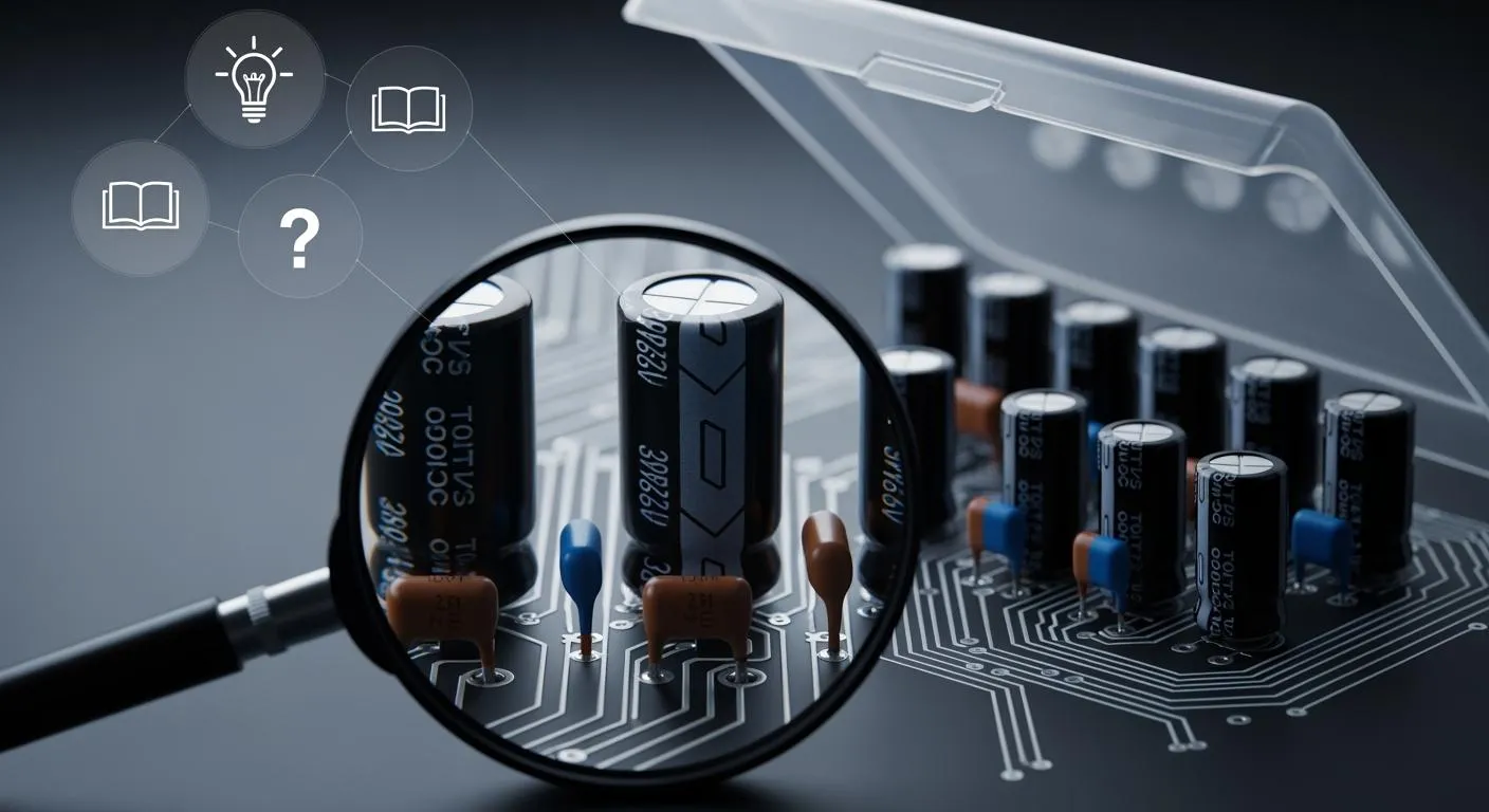
When you pick up a capacitor, you often see numbers, letters, or bands printed on its body. These markings help you read and
When you pick up a capacitor, you often see numbers, letters, or bands printed on its body. These markings help you read and understand capacitor codes, which tell you the value and tolerance of the component. Knowing how to use a capacitor code chart helps you select the right capacitor for your project. Different systems exist around the world. For example, North America uses EIA-198 codes, while other regions may use IEC or JIS systems, as shown below:
| Coding System | Description | Region of Use |
|---|---|---|
| EIA-198 | A three-digit code indicating capacitance value, primarily used in North America. | North America |
| IEC | A three-digit code often accompanied by letters for tolerance and dielectric material. | International |
| JIS | Specific codes for various capacitor types, varying significantly based on type. | Japan |
You do not need advanced skills to start. With some practice, you will quickly gain confidence in reading any capacitor you find.
Key Takeaways
- Understanding capacitor codes is essential for selecting the right component for your project. This knowledge prevents mistakes that can lead to circuit failures.
- Always double-check capacitor markings before installation. This habit helps avoid costly errors and ensures your projects are safe and reliable.
- Use a capacitor code chart to decode markings accurately. This tool simplifies the process of finding capacitance values and prevents confusion.
- Pay attention to voltage and tolerance markings. These details are crucial for ensuring your circuit operates correctly and safely.
- Practice reading different capacitor types and their codes. Gaining experience builds confidence and improves your ability to select the right components.
Why Decode Capacitor Codes
Preventing Mistakes
You might think a small marking on a capacitor is not important, but it can make a big difference. If you misread a code, you could pick the wrong capacitor for your project. This mistake can cause your circuit to fail or even create safety risks. For example, using a capacitor with the wrong value in a power supply can lead to poor filtering. The output may become unstable, and your device might not work as expected.
Tip: Always double-check the markings before you install a capacitor. This habit helps you avoid costly errors and keeps your projects safe.
Ensuring Performance
When you choose the correct capacitor, your circuit works as designed. The right value helps control voltage, filter signals, and store energy. If you use the wrong capacitor, your circuit may not perform well. You might notice noise, flickering lights, or even total failure.
- Misreading capacitor markings can lead to circuit failure, reduced performance, or safety hazards.
- In a power supply circuit, selecting the wrong capacitor value can result in insufficient filtering, leading to unstable output.
You can trust your circuit more when you know how to decode capacitor codes. This skill gives you confidence and helps you build reliable electronics. Every time you read a code correctly, you improve your results and avoid problems.
Capacitor Codes and Markings
Understanding capacitor codes and markings helps you choose the right component for your project. You will see different types of markings and codes on capacitors. Each type gives you important information about the value, voltage, and sometimes the polarity of the capacitor.
Here is a table showing common capacitor types and their markings:
| Capacitor Type | Markings Description |
|---|---|
| Electrolytic Capacitors | Markings often include the value and working voltage, e.g., 22µF 50V, with a bar indicating the negative terminal. |
| Leaded Tantalum Capacitors | Values are marked in microfarads, e.g., 22µF 6V, indicating a 22µF capacitor with a maximum voltage of 6V. |
| Ceramic Capacitors | Markings are concise, often in picofarads, e.g., 10n for 10nF or 510pF for 0.51nF. |
| SMD Ceramic Capacitors | Typically lack markings due to size constraints; values may be shown directly when space allows. |
| SMD Tantalum Capacitors | Values are shown directly, with simple three-figure formats used when space permits. |
| Temperature Coefficient Codes | Standardized codes indicating temperature coefficients, e.g., C0G for 0 PPM/°C. |
| Polarity Markings | Important for polarized capacitors, often indicated by a bar or stripe; e.g., negative lead marked with a stripe. |
Numeric Codes
You will often see numeric codes on small capacitors. These codes use three or four digits to show the value. For example, "104" means 100,000 picofarads. The first two digits are the value, and the last digit is the multiplier. Reading capacitor codes like this helps you quickly find the right value. Numeric codes appear often in capacitor marking codes, especially for ceramic types.
Alphanumeric Codes
Alphanumeric codes use numbers and letters together. You might see "100p" for 100 picofarads or "22u" for 22 microfarads. Letters can also show tolerance or voltage. This style of capacitor marking codes makes it easy to read the value and other details at a glance. Industry standards, such as those from the EIA, help keep these markings and codes clear and consistent.
Color Bands
Some capacitors use color bands, similar to resistors. Each color stands for a number. For example, a red band means "2" and an orange band means "3". The next band shows the multiplier, like green for ×10^5. The last band may show tolerance. You can use a capacitor color code chart to help with reading capacitor codes that use color. Colour bands are less common today but still appear on some older or specialty capacitors. Colour and colour code systems help you decipher capacitor symbols without numbers or letters.
SMD Markings
Surface-mount capacitors (SMD) often have very small markings or none at all. SMD capacitor identification can be tricky because of the size. When markings exist, they use short codes or numbers. You may need a chart or datasheet for smd capacitor identification. Some SMD tantalum capacitors use three-figure codes, while SMD ceramic capacitors may have no markings. SMD capacitor identification is important for modern electronics.
Polarity Symbols
Some capacitors, like electrolytic and tantalum types, are polarized. You must install them the right way. Look for a stripe or bar on the body. This marking shows the negative or positive terminal. Polarity markings and codes help prevent mistakes. Always check for these capacitor markings before soldering.
Note: Markings and codes follow industry standards to make sure you can identify and use capacitors safely and correctly.
Identify Marking Type
Visual Inspection
When you start identifying and selecting capacitors, the first step is to look closely at the component. You can spot different types of capacitor markings by checking for numbers, letters, or colored bands on the body. Each marking style gives you clues about the value and type of the capacitor.
To decode color band markings, follow these steps:
- Find the first band and note its color (for example, brown stands for 1).
- Look at the second band (black means 0).
- Check the third band for the multiplier (red equals 100).
- Multiply the numbers to get the capacitance value (for example, 10 x 100 = 1,000 pF or 1 nF).
You can use this table to help you read the color bands:
| Band Colour | Digit A | Digit B | Multiplier D | Tolerance (T) > 10pF | Tolerance (T) < 10pF |
|---|---|---|---|---|---|
| Black | 0 | 0 | x1 | ± 20% | ± 2.0pF |
| Brown | 1 | 1 | x10 | ± 1% | ± 0.1pF |
| Red | 2 | 2 | x100 | ± 2% | ± 0.25pF |
| Orange | 3 | 3 | x1,000 | ± 3% | |
| Yellow | 4 | 4 | x10,000 | ± 4% | |
| Green | 5 | 5 | x100,000 | ± 5% | ± 0.5pF |
| Blue | 6 | 6 | x1,000,000 | ||
| Violet | 7 | 7 | |||
| Grey | 8 | 8 | x0.01 | +80%,-20% | |
| White | 9 | 9 | x0.1 | ± 10% | ± 1.0pF |
| Gold | x0.1 | ± 5% | |||
| Silver | x0.01 | ± 10% |
Some capacitors use alphanumeric codes instead of color bands. For example:
- n47 means 0.47nF
- 4n7 means 4.7nF
- 47n means 47nF
- 100K means 100 x 1,000pF or 100nF
Tip: Always check both sides of the capacitor. Some markings may be small or hidden.
Common Styles
You will see several common styles when you inspect capacitors. Electrolytic capacitors, which you often find in consumer electronics, have a band on the cathode side to show the negative terminal. The SMT Can style uses a black mark on the top, while the SMT Case style marks the anode side. PTH Radial capacitors usually have a contrasting stripe down the negative side. These markings help you place the capacitor correctly and prevent damage.
You may also notice that the types of capacitor markings vary by the capacitor’s construction. Color bands appear mostly on older or specialty capacitors. Alphanumeric codes are common on modern ceramic and film capacitors. Mastering capacitor codes helps you quickly identify the right part for your project.
Note: Careful visual inspection and understanding the marking styles make identifying and selecting capacitors much easier.
Decoding Capacitor Codes
Decoding capacitor codes helps you find the right value for your project. You use a capacitor code chart to translate markings into actual capacitance. This process makes capacitor value lookup easy and accurate. You can avoid mistakes and build circuits that work well.
Using Capacitor Code Chart
You start decoding capacitor codes by following a few clear steps. A capacitor code chart gives you the information you need to match markings to values. Here is how you use a common capacitor code chart:
- Identify the capacitor type. Check if you have a ceramic, electrolytic, tantalum, or another type. This step helps you choose the right coding system.
- Look for markings. Find numbers, letters, color bands, or polarity symbols on the capacitor. For SMD capacitors, you may need to check documentation because markings are often missing.
- Decode the capacitance. Use the numeric code or EIA capacitor codes to find the value. For example, "104" means 0.1 μF. If you see "A5," look it up in the chart to get 0.1 μF.
- Check tolerance and voltage. Look for extra letters or numbers. "K" means ±10% tolerance. "50" means 50V.
- Verify polarity. For polarized capacitors, find the positive and negative terminals. This step prevents damage.
Tip: Always use a capacitor code chart for capacitor value lookup. This habit helps you avoid errors and makes decoding capacitor codes simple.
You can find a common capacitor code chart online or in datasheets. These charts show how to read capacitor markings and convert them to capacitance values.
Three-Digit and Four-Digit Codes
You often see three-digit or four-digit codes on capacitors. These codes help you find the capacitance quickly. The first two digits show the significant figures. The third digit is the multiplier. For four-digit codes, the first three digits are the significant figures, and the last digit is the multiplier.
For example, if you see "106," you multiply 10 by 10^6. This gives you 10,000,000 pF, or 10 μF. If you see "223," you multiply 22 by 10^3. This gives you 22,000 pF, or 22 nF. You can use a capacitor code chart for capacitor value lookup and get the correct value every time.
- Code "106" means 10 μF (10,000,000 pF).
- Code "223" means 22 nF (22,000 pF).
- Code "474" means 0.47 μF (470,000 pF).
You use eia capacitor codes for many ceramic and film capacitors. These codes make decoding capacitor codes fast and reliable.
Multiplier and Units
Multipliers and unit indicators help you convert codes to actual values. You see numbers like "470," "471," or "472" on the capacitor. The last digit tells you the multiplier. You use a common capacitor code chart to match the code to the capacitance.
Here is a table that shows how multipliers work for capacitor value lookup:
| Code | Significant Figures | Multiplier | Capacitance |
|---|---|---|---|
| 470 | 47 | 0 (1) | 47 pF |
| 471 | 47 | 1 (10) | 470 pF |
| 472 | 47 | 2 (100) | 4,700 pF / 4.7 nF |
| 473 | 47 | 3 (1,000) | 47,000 pF / 47 nF / 0.047 µF |
| 474 | 47 | 4 (10,000) | 470,000 pF / 470 nF / 0.47 µF |
| 475 | 47 | 5 (100,000) | 4,700,000 pF / 4.7 µF |
| 476 | 47 | 6 (1,000,000) | 47 µF |
You also see unit indicators like "p" for picofarads, "n" for nanofarads, and "u" for microfarads. For example, "100p" means 100 picofarads. "22u" means 22 microfarads. These units help you understand the value at a glance.

You use eia capacitor codes and a capacitor code chart for capacitor value lookup. This method helps you decode capacitor codes and find the right value for your circuit.
Note: Always check the units and multipliers when decoding capacitor codes. This step ensures you get the correct value and avoid mistakes.
You now know how to use a capacitor code chart, read three-digit and four-digit codes, and understand multipliers and units. You can use a common capacitor code chart for capacitor value lookup and decode capacitor codes with confidence. This skill helps you select the right capacitor and build reliable circuits.
Voltage and Tolerance Codes
Voltage Markings
When you look at a capacitor, you will often see numbers or symbols that show the breakdown voltage. This value tells you the highest voltage the capacitor can handle before it fails. You must always check the breakdown voltage before using a capacitor in your circuit. If you use a voltage higher than the breakdown voltage, the capacitor may burst or stop working.
Electrolytic capacitors have clear voltage markings. You will see a number followed by "V," such as "16V" or "50V." This marking shows the breakdown voltage. The cathode side usually has a '-' symbol and sometimes a colored strip. The anode lead is often longer, making it easy to spot. You must connect the positive and negative leads correctly. If you reverse the voltage, the capacitor can fail and burst. Always match the breakdown voltage to your circuit needs.
Other types of capacitors, like ceramic or tantalum, also show the breakdown voltage. You may see markings like "25V" or "100V" printed on the body. These capacitor markings help you choose the right part and avoid damage. You should never use a capacitor with a breakdown voltage lower than your circuit voltage.
Tip: Always check the breakdown voltage on the capacitor before installation. This step keeps your circuit safe and prevents failures.
Tolerance Letters
Capacitor tolerance tells you how much the actual value can change from the number printed on the capacitor. You will see tolerance letters or colored bands on many capacitors. These markings help you understand how close the real value is to the stated value.
You can use a tolerance code chart to read these markings. Common tolerance letters include "K" for ±10%, "J" for ±5%, and "F" for ±1%. For example, if you have a 100µF capacitor with a ±20% tolerance, the real value could be anywhere from 80µF to 120µF. This range is important when you need precise values in your circuit.
Here are some facts about capacitor tolerance:
- The tolerance of a capacitor shows how much the value can change.
- You may see tolerance shown as colored bands or letters.
- Common capacitor tolerance values are ±5%, ±10%, and ±20%.
- Some capacitors have very tight tolerance, such as ±1%.
- You should always check the tolerance code chart to know the exact range.
When you select a capacitor, make sure the tolerance fits your project. If you need high accuracy, choose a capacitor with a low tolerance. If your circuit can handle some variation, a higher tolerance is fine. Understanding capacitor tolerance helps you build reliable circuits and avoid problems.
Note: Always use the tolerance code chart to check the range of your capacitor. This habit helps you pick the best part for your needs.
Special Markings
Temperature Coefficient
You may notice special codes on some capacitors that tell you how their value changes with temperature. These codes help you understand if a capacitor will stay stable or if its value will shift as things heat up or cool down. Manufacturers use different systems to show the temperature coefficient on capacitor markings.
- You might see codes like "NP0" or "N220" on class 1 ceramic capacitors. "NP0" means the value does not change much with temperature.
- Some capacitors use a two-letter code, following the IEC/EN 60384-8/21 standard. This code shows both the temperature coefficient and the tolerance.
- The EIA RS-198 standard uses a three-character code. The first letter tells you the main figure for how much the value changes per degree. The second character shows the multiplier. The third letter gives the maximum tolerance in parts per million per kelvin (ppm/K).
For example, if you see a code like "C0G," you know the capacitor will stay very stable as the temperature changes. These markings help you pick the right capacitor for circuits that need steady performance.
Tip: Always check the temperature coefficient if your circuit will face big temperature changes. This step helps you avoid problems with drifting values.
Polarity Indicators
Some capacitors have a positive and a negative side. You must connect them the right way, or they can fail. Polarity indicators make this easy to spot.
- Electrolytic capacitors often have black-gray or green-black bodies. The longer pin shows the positive side. You may also see a stripe or minus sign on the negative side.
- Tantalum capacitors usually look yellow. The marked end shows the positive pole. The negative side sits at the opposite end.
Tantalum capacitors use high-purity tantalum powder and a special oxide layer. Electrolytic capacitors use a metal anode with an oxidized surface. Both types need you to pay attention to polarity. Always look for these special capacitor markings before you install the part.
Note: If you connect a polarized capacitor the wrong way, it can get damaged or even burst. Always double-check the markings before soldering.
Decoding Different Capacitor Types
Understanding how to read different capacitor markings helps you choose the right part for your project. Each type of capacitor uses its own code style. You can use the table below to compare how the main types display their values and other details:
| Capacitor Type | Marking Format Example | Additional Notes |
|---|---|---|
| Electrolytic Capacitor | 22µF 50V | Polarity marked by a bar indicating the negative terminal. |
| Tantalum Capacitor | 22 6V | Values marked in microfarads, with a '+' sign near the positive lead. |
| Ceramic Capacitor | 10n or n51 | Markings often in picofarads, with concise formats due to smaller size. |
| SMD Ceramic Capacitor | N/A | Often no markings due to small size; loaded into machines without need for markings. |
| SMD Tantalum Capacitor | 47 | Simple three-figure format used when space allows; polarity indicated by a bar across one end. |
Electrolytic Capacitor Codes
You will see that an electrolytic capacitor usually has its value and voltage printed right on the body, such as "22µF 50V." The negative terminal is marked with a stripe or bar. This marking helps you avoid connecting the capacitor the wrong way. Most electrolytic capacitors are polarized, so you must check the markings before use. You may also find a longer lead on the positive side. Always match the voltage rating to your circuit. If you use a supercapacitor, you will notice similar markings, but these parts store much more energy.
Tantalum Capacitor Codes
A tantalum capacitor often shows its value in microfarads, like "22 6V." You will see a "+" sign near the positive lead. This marking helps you connect the capacitor correctly. Tantalum capacitors are smaller than most electrolytic capacitors, but they are also polarized. You must pay close attention to the markings to prevent damage. Some SMD tantalum capacitors use a three-digit code for the value and a bar to show polarity.
Ceramic Capacitor Codes
A ceramic capacitor uses short codes, such as "10n" or "n51." These markings show the value in picofarads or nanofarads. Manufacturers use a three-character alphanumeric system for many ceramic capacitors. This system helps you quickly find the value, tolerance, and sometimes the temperature coefficient. Ceramic capacitors are not polarized, so you can install them in either direction. International standards like IEC and EIA help keep these codes clear and consistent.
SMD Capacitor Codes
SMD capacitors are very small. Many SMD ceramic capacitors have no markings at all. Machines place these parts on circuit boards, so markings are not needed. SMD tantalum capacitors may use a simple three-figure code and a bar to show polarity. You must use a datasheet or code chart to identify unmarked SMD capacitors. Standardized codes and international rules make it easier to understand these parts, even when markings are missing.
Note: International standards, such as IEC and EIA, help create clear and consistent capacitor markings. This makes it easier for you to select the right capacitor for any project.
Troubleshooting Capacitor Codes

Unmarked or Faded Codes
Sometimes you find a capacitor with no visible markings or faded codes. This situation can make identifying unknown capacitor codes tricky. You have several ways to figure out the value and type:
- Use a multimeter with a capacitance setting. This tool helps you measure the actual value of the capacitor. Always remove the capacitor from the circuit before testing.
- Try an LCR meter. This device gives you accurate readings for capacitance, especially if you desolder the capacitor first.
- Look closely at the capacitor for faint numbers or letters. Sometimes, you can spot clues under good lighting or with a magnifying glass.
- Check the shape, size, and color. These physical features sometimes hint at the type or value.
- Search for datasheets or manufacturer guides. Many companies provide information about their marking systems.
Tip: Always discharge the capacitor before testing to stay safe.
If you still cannot identify the value, you may need to compare it with similar capacitors from the same device.
Non-Standard Codes
You may come across capacitors with codes that do not match standard charts. Identifying unknown capacitor codes in these cases requires extra steps. A multimeter can help you verify the capacitance. Here is a simple way to use a multimeter for this task:
- Discharge the capacitor using a resistor.
- Set your multimeter to the capacitance mode.
- Remove the capacitor from the circuit.
- Connect the leads to the capacitor terminals.
- Wait for the reading to stabilize.
- Use the Relative mode if you measure very small values.
If you still have doubts, check the manufacturer's website or ask in electronics forums. Many hobbyists and engineers share tips for decoding rare or custom markings.
Note: Using these methods helps you avoid mistakes and keeps your projects running smoothly, even when you face hard-to-read capacitor codes.
Practical Tips and Examples
Sample Decoding Walkthroughs
You can build your confidence by practicing with real-world examples. Here are some ways you might decode capacitor markings in common circuits:
- Filter Circuits: You find a capacitor marked "104" in a power supply. You check your chart and see that "104" means 100,000 picofarads, or 0.1 microfarads. This value helps reduce unwanted AC noise.
- Timing Circuits: You see a capacitor labeled "223" in an oscillator. The code "223" stands for 22,000 picofarads, or 22 nanofarads. This value, combined with a resistor, sets the timing for the circuit.
- Coupling Circuits: You spot a capacitor marked "10u" in an amplifier. This means 10 microfarads. It blocks DC while letting AC signals pass between stages.
Tip: Always use a code chart when you see unfamiliar markings. This habit helps you avoid mistakes.
Best Practices
You can improve your accuracy when reading capacitor codes by following these steps:
- Use a magnifying glass or other magnification tools for small capacitors. Tiny markings can be hard to see with the naked eye.
- Think about the circuit where you found the capacitor. The function of the circuit can give you clues about the right value.
- Check the manufacturer's datasheet if you are unsure about a marking. Datasheets often explain special codes or symbols.
- Look for signs of wear or damage. Scratches or faded markings can make it hard to read the code. Always double-check if something looks unclear.
Note: Careful inspection and cross-referencing help you avoid errors and keep your projects running smoothly.
You will find that practice makes decoding capacitor codes much easier. Each time you read a marking, you gain more skill and confidence.
You build reliable circuits when you accurately read capacitor codes and markings. Practice using code charts and always check reference materials to improve your skills. For deeper understanding, explore guides like "How to Interpret Capacitor Markings," which explains common markings and their meanings. Careful attention to each capacitor helps you avoid mistakes and ensures your electronics work as expected. Your focus on details makes a big difference in every project.
FAQ
How do you know if a capacitor is polarized?
You can check for a stripe or minus sign on one side. The longer lead usually marks the positive terminal. Always install polarized capacitors with the correct orientation to prevent damage.
What does the “104” marking mean on a capacitor?
The code “104” means 100,000 picofarads, or 0.1 microfarads. The first two digits are the value. The third digit shows the number of zeros to add.
Can you use a capacitor with a higher voltage rating?
Yes, you can use a capacitor with a higher voltage rating. It will work safely in your circuit. Never use a capacitor with a lower voltage rating than your circuit requires.
What should you do if a capacitor has no markings?
Use a multimeter with a capacitance setting to measure the value. Remove the capacitor from the circuit before testing. You can also compare it with similar capacitors or check the device’s schematic.
Why do some capacitors have no markings at all?
Small SMD capacitors often have no markings because of their size. Manufacturers rely on automated machines for placement. You can identify these parts using the circuit diagram or manufacturer’s documentation.