

STM32F103C8T6 Microcontroller: Pinout, Memory, and Peripheral Overview
You can use the STM32F103C8T6 Microcontroller in many projects. It works well when you need good performance and low power use. You see this chip in e
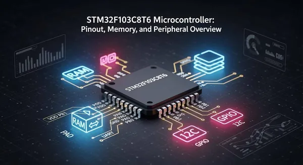
You can use the STM32F103C8T6 Microcontroller in many projects. It works well when you need good performance and low power use. You see this chip in electronics, automation, medical tools, and smart devices. You get important hardware features like many GPIO pins, flexible memory, and different ways to connect. The table below shows its main features:
Feature | STM32F103C8T6 |
|---|---|
GPIO Pins | 32 |
FLASH (ROM) | 64kB/128kB |
RAM | 20kB |
UART | 3 |
SPI | 2 |
I2C | 2 |
Timers | 7 |
This article gives you easy tables and clear explanations. They help you finish your work faster and better.
Key Takeaways
The STM32F103C8T6 Microcontroller has 32 GPIO pins. It also has 10 analog input pins. You can connect sensors and displays to these pins. This gives you many options for your project.
It has 64KB of Flash memory. It also has 20KB of SRAM. This microcontroller works well for medium-sized projects. You can store data and get it quickly.
You can use different communication interfaces. These include USART, SPI, and I2C. They help you connect and share data with other devices.
You can use low power modes to save battery. Use standby or shutdown modes when you do not need full power. This helps your project last longer.
Pick the STM32 model that fits your project. The STM32F103C8T6 works for most uses. The STM32F103CBT6 has more memory for bigger programs.
STM32F103C8T6 Microcontroller Pinout
Pin Configuration Overview
You work with a chip that has 48 pins. You find 37 pins for general-purpose input/output (GPIO). You also get 10 pins for analog input. Some pins have special functions, like reset and boot. The table below helps you see how these pins are distributed:
Feature | Count |
|---|---|
Total Pins | 48 |
GPIO Pins | 37 |
Analog Input Pins | 10 |
You use these pins to connect sensors, displays, and other devices. You can control LEDs, read switches, or send signals to motors. The STM32F103C8T6 Microcontroller gives you flexibility for many projects.
GPIO and Alternate Functions
You use GPIO pins to read digital signals or send them out. You can set each pin as input or output. Many pins support alternate functions. You switch a pin from basic GPIO to a special role, like UART, SPI, I2C, or PWM. This lets you connect to other chips or modules.
Here is a quick look at some key pin functions:
Function | |
|---|---|
PC_13 | On-board LED |
PA_2 | SERIAL_TX |
PA_3 | SERIAL_RX |
PB_8 | I2C_SCL |
PB_9 | I2C_SDA |
PA_7 | SPI_MOSI |
PA_6 | SPI_MISO |
PA_5 | SPI_SCK |
PB_6 | SPI_CS |
A0 | Analog Input |
D14 | Digital Input |
Tip: You can change a pin’s function in your code. This helps you use the same hardware for different tasks.
You find that alternate functions make your design more powerful. You can use one pin for communication or control, depending on your needs.
Analog Inputs and Special Pins
You use analog input pins to read signals from sensors. These pins measure voltage and convert it to a digital value. The STM32F103C8T6 Microcontroller gives you 10 analog input pins. You get 12-bit resolution, which means you can measure values from 0 to 4095.
Analog Pins | Resolution |
|---|---|
PA0-PA7, PB1 | 12-bit |
You connect temperature sensors, light sensors, or other analog devices to these pins. You also find special pins for reset and boot. These pins help you start or program the chip.
Note: You should use analog pins for signals that change smoothly, like temperature or light.
Power and Ground Pins
You power the STM32F103C8T6 Microcontroller with a voltage between 2.0V and 3.6V. You connect the ground pin (VSS) to your circuit’s ground. The table below shows the main power details:
Parameter | Value |
|---|---|
Operating Voltage Range | |
Ground Pin Configuration | VSS (Pin 48) |
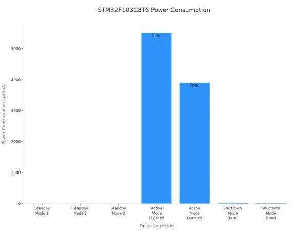
You want your design to use less power. The chip supports different modes. You see how much power each mode uses in the chart below:
Operating Mode | Power Consumption (Typical) |
|---|---|
Standby Mode 1 | 3.4 µA |
Standby Mode 2 | 3.2 µA |
Standby Mode 3 | 2.0 µA |
Active Mode (72MHz) | 5.5 mA |
Active Mode (48MHz) | 3.9 mA |
Shutdown Mode (Run) | 24 µA |
Shutdown Mode (Low) | 14 µA |
Tip: You save battery life by using standby or shutdown modes when your project does not need full power.
You should follow good PCB layout practices for power and ground pins. Place a 0.1μF capacitor close to each power pin. Use surface-mount capacitors for better noise suppression. Keep the power, capacitor, and ground points close together. Place the smallest capacitors nearest to the chip. For high-speed designs, put capacitors on the same side as the chip.
You now understand how to use the STM32F103C8T6 Microcontroller pinout for your project. You can connect many devices, use different functions, and keep your design efficient.
Memory Architecture
Flash Memory (64 KB)
You store your program code and important data in Flash memory. The STM32F103C8T6 Microcontroller gives you 64 KB of Flash. This memory keeps your code safe even when you turn off the power. You can update the Flash when you need to change your program. Many microcontrollers in this class offer similar Flash sizes. For example, the GigaDevice GD32F103C8T6 also has 64 KB of Flash. Here is a quick comparison:
Microcontroller | Flash Memory Size | Operating Frequency | RAM Size |
|---|---|---|---|
STM32F103C8T6 | 64KB | 72MHz | 20KB |
GigaDevice GD32F103C8T6 | 64KB | 108MHz | 20KB |
Tip: You should use Flash memory for code and data that do not change often.
SRAM (20 KB)
You use SRAM for variables and data that change while your program runs. The STM32F103C8T6 Microcontroller has 20 KB of SRAM. This memory works fast and helps your program run smoothly. When you turn off the power, SRAM loses its data. You should store only temporary data in SRAM. You can use this space for sensor readings, calculations, or communication buffers.
Memory Map and Access
You work with a simple memory map. Flash memory starts at address 0x08000000. SRAM starts at address 0x20000000. You can access both types of memory directly in your code. The microcontroller reads from Flash to run your program. It uses SRAM for fast data storage and quick access.
Memory speed matters for your project. Flash memory has a latency of 100 cycles and an execution time of 400 nanoseconds. SRAM is faster, with a latency of 50 cycles and an execution time of 200 nanoseconds.
Memory Type | Latency (Cycles) | Execution Time (ns) |
|---|---|---|
Flash | 100 | 400 |
SRAM | 50 | 200 |
Note: You get better performance when you use SRAM for tasks that need speed.
You now know how to use the memory in your STM32F103C8T6 Microcontroller. You can store your code, save data, and make your project run faster by choosing the right memory for each task.
Peripheral Interfaces
Communication (USART, SPI, I2C, CAN, USB)
You can link the STM32F103C8T6 Microcontroller to many devices. These interfaces help you send and get data. You use them with sensors, computers, and other microcontrollers. Each one works in its own way and at its own speed.
Interface | Description |
|---|---|
USART | Serial communication for debugging or connecting to serial devices. |
SPI | Fast and reliable communication with sensors and memory chips. |
I2C | Simple two-wire connection for multiple devices. |
CAN | Used in cars and factories for strong, error-free communication. |
USB | Connects to computers and USB devices for data transfer. |
You use USART to send text to your computer. It also helps you talk to GPS modules. SPI is good for quick data swaps with displays or memory cards. I2C lets you use just two wires for many sensors. CAN is used for networks in cars or machines. USB lets you link your project to a PC.
Tip: Pick the best interface for your project. Think about speed, distance, and how many devices you need.
Timers and PWM
You use timers in the STM32F103C8T6 Microcontroller to control time. Timers help you count events or make pulses for motors and LEDs.
Timer Type | Key Features | Typical Use Cases |
|---|---|---|
General-Purpose Timers | 16-bit or 32-bit counters, up/down counting, PWM generation, input capture | Periodic interrupts, PWM for motor control |
Advanced-Control Timers | Dead-time insertion, complementary outputs, designed for motor control | Motor control, high-resolution PWM |
Basic Timers | Simple 16-bit timers, mainly used for time base generation | Time delays, triggering DACs |
System Timer (SysTick) | 24-bit timer, high-priority interrupt | RTOS tick timer, delay functions |
Low-Power Timers | Designed for low-power modes, 16-bit with wake-up capability | RTC-style timekeeping, wake-up timers |
Real-Time Clock (RTC) | Counts real time, calendar, alarms | Calendar, time-stamped data logging |
PWM helps you change how bright LEDs are. It also lets you set motor speed. General-purpose timers make regular time events. The advanced timer gives extra help for motor control. The system timer keeps track of time in your code. The real-time clock counts time even when the chip sleeps.
You can use timers for many things. You can blink an LED, make a beep, or measure time.
Analog Peripherals (ADC)
You use analog-to-digital converters (ADCs) to measure signals. ADCs change analog voltages into digital numbers for your code.
Specification | Details |
|---|---|
Resolution | |
Input Channels | Up to 18 multiplexed channels |
Sampling Rate | 1 µs at 56 MHz (1.17 µs at 72 MHz) |
Analog Input Range | VREF– ≤ VIN ≤ VREF+ |
Voltage Input Range | 0 ~ 3.3V |
12-bit resolution lets you measure from 0 to 4095.
You can hook up lots of sensors to the input channels.
You can set how fast each channel samples.
You can pick single, continuous, scan, or discontinuous modes.
You can start conversions with an outside signal.
The ADCs are accurate to about +/- 1% with high impedance loads. You can trust these readings for most sensors.
Note: Use the ADC for signals like temperature, light, or voltage that change slowly.
Other Features (CRC, Watchdog)
You get extra features to keep your project safe and working.
Cyclic Redundancy Check (CRC): This checks your data for mistakes. It helps you spot errors when sending data.
Watchdog Timers: These timers watch your program. If your code stops, the watchdog resets the microcontroller. This keeps your system running if something goes wrong.
You can use these features to make your project stronger. CRC helps you trust your data. The watchdog timer stops crashes from hurting your system.
Tip: Always turn on the watchdog timer in important projects. This helps you avoid surprise stops.
Now you know how to use the main peripherals in the STM32F103C8T6 Microcontroller. You can connect, control, and protect your project with these tools.
Model Comparison
STM32F103C8T6 vs STM32F103CBT6
You may wonder how the STM32F103C8T6 and STM32F103CBT6 compare. Both chips have the same number of pins and the same amount of SRAM. You get 48 pins on each chip, so you can connect the same number of devices. The main difference is the size of the Flash memory. The STM32F103CBT6 gives you twice as much Flash as the STM32F103C8T6. This means you can store bigger programs or more data. Both chips support key peripherals like CAN and USB.
Feature | STM32F103C8T6 | STM32F103CBT6 |
|---|---|---|
Flash Memory | 64KB | |
SRAM | 20KB | 20KB |
Pin Count | 48 pins | 48 pins |
Available Peripherals | CAN, USB, etc. | CAN, USB, etc. |
Tip: If your project needs more program space, you should pick the STM32F103CBT6.
STM32F103C8T6 vs STM32F103C6T6
You also might look at the STM32F103C6T6. This chip has less Flash and less SRAM than the STM32F103C8T6. You get only 32KB of Flash and 10KB of SRAM. The pin count stays the same at 48 pins. Most basic peripherals are still there, but you may find fewer advanced features. If you want to build a simple project, the STM32F103C6T6 can work well.
STM32F103C8T6: 64KB Flash, 20KB SRAM, 48 pins
STM32F103C6T6: 32KB Flash, 10KB SRAM, 48 pins
You should choose the STM32F103C8T6 if you need more memory for your code or data.
Selection Tips
You want to pick the right chip for your project. Here are some tips:
Choose the STM32F103C8T6 Microcontroller for most medium projects. You get a good balance of memory and features.
Pick the STM32F103CBT6 if you need more Flash memory for large programs.
Use the STM32F103C6T6 for simple tasks or when you want to save money.
Always check if your project needs special peripherals like CAN or USB.
Think about future updates. More memory gives you room to grow.
🛠️ You can always upgrade to a bigger chip if your project gets more complex.
You now understand the STM32F103C8T6 Microcontroller’s pinout, memory, and peripherals. When you look at pinout tables or the clock tree diagram, you can fix design problems fast. This knowledge helps you make better embedded systems. For more practice, check out these helpful resources:
Title | Description |
|---|---|
Learn STM32 features with examples and tutorials. | |
The Insider's Guide to STM32 ARM-Based Microcontroller | Start programming STM32 with easy, practical steps. |
Programming with STM32 | Create your own STM32 programs with simple guides. |
Try these next steps to grow your skills.
FAQ
What development tools can you use with the STM32F103C8T6?
You can use STM32CubeIDE, Keil uVision, or PlatformIO. These tools help you write, debug, and upload code. You can also use Arduino IDE with the STM32duino core for simple projects.
How do you program the STM32F103C8T6 microcontroller?
You connect the microcontroller to your computer using a USB-to-serial adapter or ST-Link programmer. You use software like STM32CubeProgrammer to upload your code. You set the BOOT0 pin high to enter programming mode.
Can you use Arduino libraries with STM32F103C8T6?
Yes, you can use many Arduino libraries. You install the STM32duino core in Arduino IDE. You write code like you do for Arduino boards. Some libraries may need small changes for STM32 compatibility.
What is the maximum clock speed you can set for STM32F103C8T6?
You can set the clock speed up to 72 MHz. This gives you fast performance for most tasks. You can lower the speed to save power if your project does not need maximum speed.


