The Ultimate Capacitor Color Code Chart
This capacitor color code chart is your primary tool for decoding capacitor codes. Mastering capacitor codes is essential. I
This capacitor color code chart is your primary tool for decoding capacitor codes. Mastering capacitor codes is essential. Industry data shows over 60% of circuit failures come from incorrect capacitor identification. This capacitor color code guide helps you read all capacitor marking codes. You can find a capacitor's capacitance value and other ratings. Use this guide for decoding capacitor codes and understanding capacitor color codes.
| Color | Significant Figure | Multiplier (pF) | Tolerance | Voltage Rating |
|---|---|---|---|---|
| Black | 0 | 1 | ±20% | - |
| Brown | 1 | 10 | ±1% | 100V |
| Red | 2 | 100 | ±2% | 250V |
| Orange | 3 | 1,000 | - | - |
| Yellow | 4 | 10,000 | - | 400V |
| Green | 5 | 100,000 | ±0.5% | - |
| Blue | 6 | 1,000,000 | ±0.25% | 630V |
| Violet | 7 | - | ±0.1% | - |
| Gray | 8 | - | - | - |
| White | 9 | - | - | - |
| Gold | - | 0.1 | ±5% | - |
| Silver | - | 0.01 | ±10% | - |
Key Takeaways
- Capacitor color codes help you find a capacitor's value. Each color stands for a number, a multiplier, or a rating.
- You read color bands from left to right. The first two bands give you the main numbers. The third band tells you how many zeros to add.
- The last bands show tolerance and voltage. Tolerance tells you how much the value can change. Voltage is the highest safe power level.
- Many capacitors use a 3-digit number code. The first two numbers are the value. The third number tells you how many zeros to add.
- Always check a capacitor's polarity. Connecting it wrong can break the capacitor and your circuit.
Reading the capacitor color code
You can master how to read capacitor markings with a simple, step-by-step process. This section guides you through decoding capacitor codes on banded components. First, you need to orient the capacitor correctly. Look for the set of bands grouped closer to one end. You will read from that end, moving across the capacitor body. Each color band has a specific meaning that helps you find the component's value.
The meaning of each color
Each color on a capacitor represents a number, a multiplier, or a rating. This system provides a compact way to print information on a small capacitor. Manufacturers adopted this method because it was easy and affordable to implement. The history of these color codes dates back to the early days of electronics.
- The Radio Manufacturers Association (RMA) first developed a color code for resistors in the 1920s.
- Radios using these color-coded parts appeared by 1930.
- The International Electrotechnical Commission (IEC) standardized the system in 1952.
- This standard was later extended to capacitors in 1968, creating the capacitor color code system we use today.
Understanding this system is the key to accurate component identification.
Identifying the value bands
The first two (or sometimes three) bands on a capacitor give you the significant digits of its capacitance value. You read these bands from left to right. The first band is the first digit, and the second band is the second digit. You can use a capacitor value lookup chart to find the number for each color.
Here is the standard mapping for the first two bands:
| Color | 1st Digit (A) | 2nd Digit (B) |
|---|---|---|
| Black | 0 | 0 |
| Brown | 1 | 1 |
| Red | 2 | 2 |
| Orange | 3 | 3 |
| Yellow | 4 | 4 |
| Green | 5 | 5 |
| Blue | 6 | 6 |
| Violet | 7 | 7 |
| Grey | 8 | 8 |
| White | 9 | 9 |
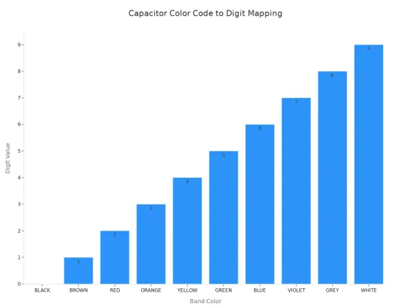
For example, if the first band is Brown and the second is Black, your significant digits are "1" and "0", making the number 10.
The multiplier band
The third band is the multiplier. This band tells you how many zeros to add to your significant digits. The final capacitance value is always measured in picofarads (pF). You can use a capacitor value lookup table for this band as well.
| Color | Multiplier (Power of Ten) |
|---|---|
| Black | ×1 |
| Brown | ×10 |
| Red | ×100 |
| Orange | ×1000 |
| Yellow | ×10000 |
| Green | ×100000 |
| Blue | ×1000000 |
| Violet | (No multiplier listed) |
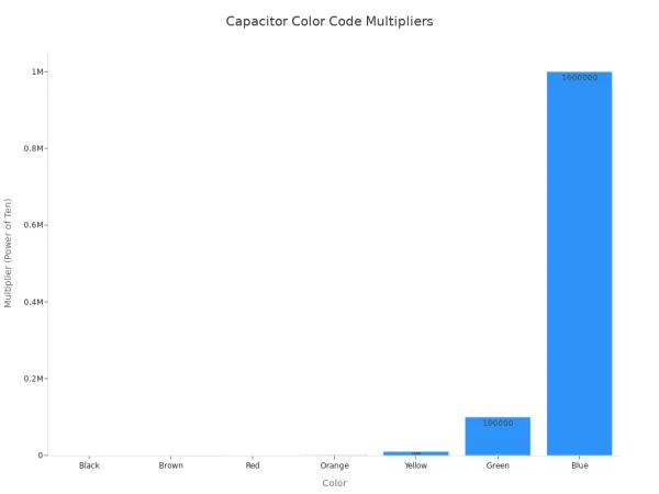
Note: Gold and Silver bands can also appear as multipliers. A Gold multiplier means you multiply by 0.1. A Silver multiplier means you multiply by 0.01.
Tolerance and voltage bands
The final bands on a capacitor indicate its tolerance and voltage rating. Tolerance tells you how much the actual capacitance can vary from its stated value. The voltage rating is the maximum voltage the capacitor can safely handle.
- The fourth band usually represents tolerance.
- The fifth band (if present) represents the working voltage.
You can use a capacitor tolerance chart to decipher capacitor symbols for tolerance.
| Color | Tolerance (+/-) |
|---|---|
| Brown | 1% |
| Red | 2% |
| Green | 0.5% |
| Blue | 0.25% |
| Violet | 0.1% |
| Gold | 5% |
| Silver | 10% |
| Black | 20% |
The voltage rating is critical for circuit safety. A dedicated color band specifies this value on many capacitor marking codes.
| Voltage Rating | Color |
|---|---|
| 100 V | Brown |
| 250 V | Red |
| 400 V | Yellow |
| 630 V | Blue |
Worked Example: Decoding a Capacitor
Let's try decoding a capacitor with the bands: Brown - Black - Orange - Gold.
- Orient the Capacitor: The bands are read from left to right.
- Value Bands:
- 1st Band (Brown) =
1 - 2nd Band (Black) =
0 - This gives you the number
10.
- 1st Band (Brown) =
- Multiplier Band:
- 3rd Band (Orange) =
×1,000 - Calculate the capacitance:
10 × 1,000 = 10,000 pF. - You can convert this value to other units: 10,000 pF is equal to 10 nF or 0.01 µF.
- 3rd Band (Orange) =
- Tolerance Band:
- 4th Band (Gold) =
±5% - This means the actual capacitance of the capacitor is between 9,500 pF and 10,500 pF.
- 4th Band (Gold) =
The complete identification for this capacitor is 10 nF with a ±5% tolerance. This process shows you how to read capacitor markings effectively.
Decoding numeric capacitor codes
Not every capacitor uses color bands. You will find that many components, especially ceramic disk and film capacitors, use a numeric system for their capacitor marking codes. This method provides a clear and compact way to display the component's specifications. Your first step in decoding capacitor codes is to understand this 3-digit system.
The 3-digit value code
You can find the capacitance of a capacitor using its 3-digit code. This system is simple to learn.
- The first two digits give you the significant figures of the value.
- The third digit is a multiplier that tells you how many zeros to add.
The final value is always in picofarads (pF). Let's look at a common capacitor marked 104.
- First two digits:
10 - Third digit (multiplier):
4(This means add four zeros) - Combine them:
10with four zeros is100,000.
So, a 104 capacitor has a capacitance of 100,000 pF. You can convert this value to make it easier to read: 100,000 pF = 100 nF or 0.1 µF. This simple capacitor value lookup method is key to correct component identification.
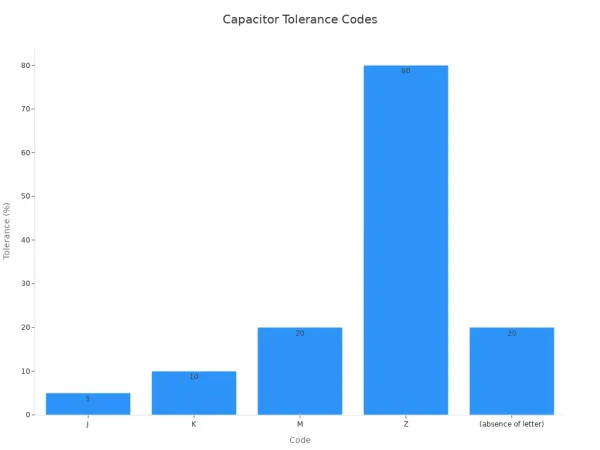
The tolerance letter code
After the 3-digit value, you will often see a letter. This letter represents the tolerance of the capacitor, which is how much its actual capacitance can vary from the stated value. You can use a quick lookup chart to find the meaning.
| Code | Tolerance |
|---|---|
| J | ±5% |
| K | ±10% |
| M | ±20% |
| Z | –20% to +80% |
Note: If a capacitor has no tolerance letter, you can assume a default tolerance of ±20%. A
104Kcapacitor, for example, has a value of 100 nF with a ±10% tolerance.
Finding the breakdown voltage
The final piece of the puzzle is the breakdown voltage. This is the maximum voltage the capacitor can safely handle. Most capacitors have this rating printed directly on their body, such as 50V or 250V. Sometimes, a capacitor uses a code. For instance, the code 2A on a capacitor indicates a voltage rating of 100V. A complete capacitor value lookup includes checking the capacitance, tolerance, and voltage.
Identifying capacitor polarity
You must correctly identify a capacitor's polarity before placing it in a circuit. This is a critical safety step. Connecting a polarized capacitor backward can cause it to fail catastrophically. Even a reverse voltage of just 1V can destroy the internal oxide layer of an electrolytic capacitor, leading to a short circuit. This failure can cause the capacitor to build up internal pressure, rupture, and leak. Tantalum capacitors are especially sensitive; incorrect polarity can cause them to smoke or even explode. Proper identification prevents damage to your components and ensures your circuit works safely.
Understanding capacitor color codes for polarity
While most polarity markings are symbols or stripes, some special types of capacitors use physical features for easy identification.
Some capacitors have their polarity marked with a chamfered edge or a specific color code. You should always check the manufacturer's datasheet if you are unsure.
This method provides another layer of visual confirmation for the component.
Markings on electrolytic types
You can easily find the polarity on most electrolytic capacitors by looking for a few common indicators. These markings clearly point out the negative and positive leads.
- Negative Stripe: Look for a prominent stripe running down the side of the capacitor can. This stripe usually contains minus signs (
-) and points to the negative lead. - Lead Length: On a new through-hole capacitor, the leads have different lengths. The longer lead is the positive (+) terminal, and the shorter lead is the a negative (-) terminal.
Always double-check these signs to correctly orient the capacitor in your circuit.
Markings on tantalum types
Tantalum capacitors often use a different marking convention than electrolytic types, which can cause confusion. For most tantalum capacitors, the markings indicate the positive lead.
- Positive Stripe: A colored stripe on the body of a tantalum capacitor typically marks the positive (+) lead.
- Plus Sign: You will often find a plus sign (
+) printed near the positive lead. This is common on both surface-mount and through-hole tantalum capacitor styles.
Remembering that the stripe on a tantalum capacitor usually means positive is key to avoiding mistakes.
You can now confidently identify any capacitor. Use the capacitor color code chart for banded types and the 3-digit system for numeric ones. Always remember that checking polarity is a critical safety step. Before handling any capacitor in a circuit, you should:
- Ensure the power is completely off.
- Safely discharge any stored energy with the proper tools.
Bookmark this guide as your go-to reference for every project. Happy building! 🛠️
FAQ
What if a capacitor has no markings?
You should measure an unmarked capacitor with an LCR meter. This tool directly tells you its capacitance value. Without any codes, you cannot guess the component's specifications. Always test the part to ensure your circuit works correctly.
Can I use a capacitor with a higher voltage rating?
Yes, you can replace a capacitor with one that has a higher voltage rating. The new component must have the same capacitance. Never use a capacitor with a lower voltage rating. It could fail and damage your circuit.
Why do some capacitors have three value bands?
Some precision capacitors use three bands for the value. You read the first three colors as significant digits. The fourth band then becomes the multiplier. This system allows for more precise capacitance values on the component.
What does the letter 'R' mean in a numeric code?
The letter R acts as a decimal point for values less than 10 pF. For example, a capacitor marked 4R7 has a value of 4.7 pF. This notation helps you read very small capacitance values easily.