Understanding Buck-Boost Converters A Simple Guide
You can think of a buck-boost converter as a versatile type of DC-to-DC switched-mode power supply. Its key feature is its unique ability to produce
You can think of a buck-boost converter as a versatile type of DC-to-DC switched-mode power supply. Its key feature is its unique ability to produce a steady output voltage. This output can be higher or lower than the input voltage. Unlike a simple buck converter or boost converter, this dc to dc converter acts like a universal power regulator. It ensures your electronics get stable power, even when the source fluctuates. The market for the dc-to-dc converter is growing fast.
| Metric | Value |
|---|---|
| Global Market Size (2024) | USD 12.21 billion |
| Projected Market Size (2032) | USD 28.47 billion |
| CAGR (2025-2032) | 9.66% |
This makes the buck boost step up converter a vital component in modern electronics.
Key Takeaways
- A buck-boost converter changes voltage up or down. It gives a steady output voltage from a changing input.
- This converter uses a switch, an inductor, a diode, and a capacitor. These parts store and release energy to control voltage.
- A PWM controller is the 'brain' of the converter. It adjusts how long the switch stays on to keep the output voltage stable.
- Buck-boost converters are useful in many devices. They power phones, solar systems, and car electronics.
- The 4-switch design is efficient. It works well for higher power needs and makes less electrical noise.
How Buck-Boost Converters Work
A buck-boost converter is a versatile type of DC-DC converter that can produce an output voltage that is either higher or lower than its input voltage. This unique capability is achieved through a clever arrangement of components and a sophisticated control mechanism. To understand how it works, let's break down its core components and the two primary operational states.
Core Components
At its heart, a buck-boost converter consists of four main components:
- A Switch (MOSFET): This is typically a Metal-Oxide-Semiconductor Field-Effect Transistor (MOSFET) that acts as a high-speed electronic switch. It rapidly turns on and off to control the flow of energy.
- An Inductor: This is a passive component that stores energy in a magnetic field when current flows through it and releases this energy when the current changes. It's the key to both stepping up and stepping down the voltage.
- A Diode: This electronic component allows current to flow in only one direction, acting as a one-way valve for electricity.
- A Capacitor: This component stores electrical energy and helps to smooth out the output voltage, providing a stable power supply to the load.
The On-State: Storing Energy
When the switch (MOSFET) is turned on, it creates a direct path from the input voltage source to the inductor. Current begins to flow from the source, through the inductor, and back to the source. During this phase, the inductor acts like a temporary energy reservoir, storing energy in its magnetic field. The output capacitor supplies the load with the energy it stored during the previous cycle. The diode is reverse-biased and does not conduct, effectively isolating the output from the input side.
The Off-State: Releasing Energy
When the switch is turned off, the path from the input voltage source is cut. The magnetic field in the inductor, which cannot change instantaneously, collapses. This collapse induces a voltage with a reversed polarity. This new voltage, now higher than the input voltage, forward-biases the diode, allowing the stored energy to flow from the inductor to the capacitor and the load. The capacitor is recharged, and the load receives its required power. This cycle of storing and releasing energy happens thousands of times per second, resulting in a regulated output voltage.
The PWM Controller
The magic behind maintaining a stable output voltage, regardless of input voltage or load changes, lies in the Pulse-Width Modulation (PWM) controller. This is the "brain" of the power supply.
A PWM controller works by adjusting the duty cycle—the ratio of the 'on' time to the total 'on' and 'off' time of the switch.
- To increase the output voltage, the controller increases the duty cycle, keeping the switch on for a longer duration. This allows more energy to be stored in the inductor, which is then released to the output.
- To decrease the output voltage, the controller reduces the duty cycle, shortening the on-time of the switch.
This control is achieved through a sophisticated feedback mechanism. Here's a simplified breakdown of how it works:
- Sensing: A feedback pin on the controller continuously measures the output voltage, usually through a voltage divider.
- Comparison: An internal component called an error amplifier compares this measured voltage to a precise, stable internal reference voltage.
- Adjustment: The output of the error amplifier then adjusts the pulse width of the signal sent to the switch. If the output voltage is too low, the pulse width is increased. If it's too high, the pulse width is decreased.
This constant feedback loop ensures the output voltage remains stable even if the input voltage fluctuates or the load's power demand changes.
| Control Method | Feedback Mechanism | Advantages | Disadvantages |
|---|---|---|---|
| Voltage Mode | Compares output voltage to a reference, adjusting the duty cycle. | Simple, good noise immunity. | Slower response to load changes. |
| Current Mode | Uses both output voltage and inductor current for feedback. | Faster response, inherent over-current protection. | More complex, sensitive to noise. |
| Hysteresis Control | Directly compares output voltage to high/low thresholds. | Very fast transient response, simple. | Variable switching frequency. |
Some advanced controllers also incorporate a soft-start function. This feature gradually increases the duty cycle when the power supply is first turned on, preventing a sudden inrush of current and ensuring a smooth, controlled rise of the output voltage to its target level. This is a critical aspect of a robust buck-boost converter design.
At Nova Technology Company (HK) Limited, we specialize in leveraging these advanced control techniques. As a proud, authorized solutions partner for Hisilicon, we have deep expertise in designing and implementing sophisticated power management systems, including those based on the versatile buck-boost converter architecture, ensuring optimal performance and reliability for your electronic devices.
The Buck Boost Step Up Converter Function
A key strength of the buck boost step up converter is its flexibility. It doesn't just perform one job. Instead, it intelligently switches between two main functions: stepping voltage down (buck mode) and stepping voltage up (boost mode). You can think of it as having two tools in one. It automatically selects the right tool based on the relationship between your input voltage and the required output voltage.
Buck Mode: Stepping Down Voltage
Your device enters buck mode when the input voltage is higher than the stable output voltage you need. Imagine your power source is a fully charged 12V battery, but your circuit requires a steady 5V. In this scenario, the buck-boost converter simplifies its operation to function just like a standard buck converter.
It achieves this by controlling the duty cycle of the main switch. A lower duty cycle means the switch is on for a shorter time. This reduces the amount of energy passed to the output, effectively "bucking" or lowering the voltage to your target level. The relationship is quite direct.
- Ideal Calculation: In a perfect world, you find the duty cycle (D) by simply dividing the output voltage (Vo) by the input voltage (Vin).
D = Vo / Vin - Practical Calculation: Real-world components have small energy losses. A more accurate formula accounts for the voltage drop across the switch (Vsw) and the diode (Vd).
D = (Vo + Vd) / (Vin + Vd - Vsw)
By precisely adjusting this duty cycle, the converter ensures a stable, lower voltage output even when the input is much higher.
Boost Mode: Stepping Up Voltage
Now, consider the opposite situation. Your input voltage drops below the level your device needs. For example, your 12V battery has drained to 9V, but your circuit still requires that steady 12V output. Here, the buck-boost converter automatically transitions to function as a boost converter.
To step up the voltage, the controller increases the switch's duty cycle. Keeping the switch on longer allows the inductor to store more energy. When the switch turns off, this large amount of stored energy is released, creating an output voltage that is higher than the input. The duty cycle (D) for an ideal boost converter is a function of both input (Vin) and output (Vout) voltages, calculated as D = (Vout - Vin) / Vout. This formula shows that as the duty cycle increases, the output voltage rises. For a more precise calculation in a real circuit, you would also factor in the voltage drops across the diode (Vd) and the switch (Vsw).
Combining Buck and Boost Principles
The true innovation of a modern buck boost step up converter is how it seamlessly combines these two modes. Most modern designs use a 4-switch non-inverting topology. This design uses four switches (MOSFETs) instead of the single switch and diode found in simpler converters. This arrangement provides superior efficiency and control.
Here is how it intelligently manages the modes:
- Buck Mode: When your input voltage is high, it uses one set of switches to create a simple buck converter path. Switches Q2 and Q4 remain off.
- Boost Mode: When your input voltage is low, it uses a different pair of switches to create a boost converter path. Switches Q1 and Q3 remain off.
There is also a special buck-boost region where all four switches may operate. This happens when the input voltage is very close to the output voltage, ensuring a smooth and glitch-free transition between modes.
A Key Advantage: Efficiency and Performance 📈 You might wonder why this 4-switch design is preferred. It offers significant advantages in efficiency, electrical noise, and performance, especially when compared to older designs like the single-inductor inverting topology (SEPIC).
The table below highlights why the 4-switch buck boost step up converter is often the superior choice for demanding applications.
| Feature | 4-Switch Buck-Boost | Single-Inductor Inverting (SEPIC) |
|---|---|---|
| Efficiency | Generally higher, especially for higher current applications (>1A). | Lower efficiency, especially at higher currents. |
| EMI/Noise | Lower EMI due to softer switching and lower switching voltages. | Higher EMI due to hard switching and larger voltage swings. |
| Stability & Loop Response | More stable and can be designed for faster response times. | Slower response due to extra components in the power loop. |
| Current Handling | A better solution for higher current applications (>1A). | More suitable for output currents below 1A. |
| Energy Storage | Stores less energy in the inductor, allowing for smaller components. | Stores the complete transfer energy, requiring larger inductors. |
This advanced control makes the 4-switch buck-boost converter an incredibly robust and efficient solution for managing power from variable sources.
Common Applications
The unique ability of a buck-boost converter to both step up and step down voltage makes it incredibly useful. You will find this versatile dc to dc converter in many modern electronics. Let's explore some common boost converter applications where it plays a critical role.
Battery-Powered Devices
You use battery-powered devices every day, like smartphones, laptops, and portable speakers. A major challenge for these gadgets is the battery's voltage. A lithium-ion battery, for example, might provide 4.2V when fully charged but drop to 3.0V as it drains. However, the sensitive components inside need a constant voltage, like 3.3V or 5V, to work correctly.
This is a perfect application for a buck-boost converter.
- When the battery is full (4.2V), the converter "bucks" the voltage down to 3.3V.
- When the battery is low (3.0V), it "boosts" the voltage up to 3.3V.
This ensures your device gets a stable power supply from start to finish, maximizing battery life and performance. The market for these converters in portable electronics is growing rapidly.
| Metric | 2023 (Estimated) | 2028 (Projected) |
|---|---|---|
| Units Shipped | 1.5 billion | 2.5 billion |
| Market Value | $3 billion | >$5 billion |
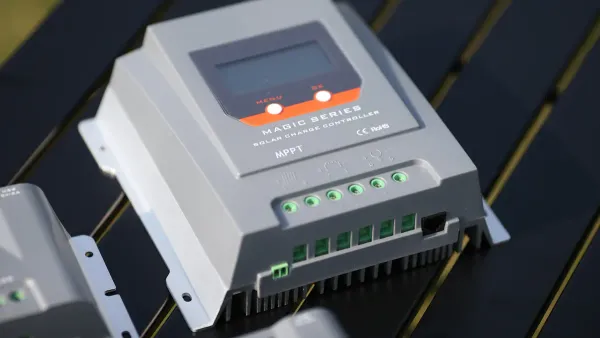
Renewable Energy Systems
Renewable energy sources like solar panels produce a very inconsistent voltage. The output changes with the amount of sunlight, cloud cover, and temperature. For example, a solar panel system might produce anywhere from 10V to 25V throughout the day. If you want to use this energy to charge a 24V battery, you need a smart power solution.
A buck-boost converter is essential here. It acts as a bridge between the solar panel and the battery.
- It takes the fluctuating input voltage from the panel.
- It delivers a constant, stable output voltage to charge the battery efficiently.
This process, often part of a Maximum Power Point Tracking (MPPT) system, ensures you capture the most energy possible from the sun. These converters can achieve an average efficiency of 85% to 92%, turning variable solar energy into reliable power.
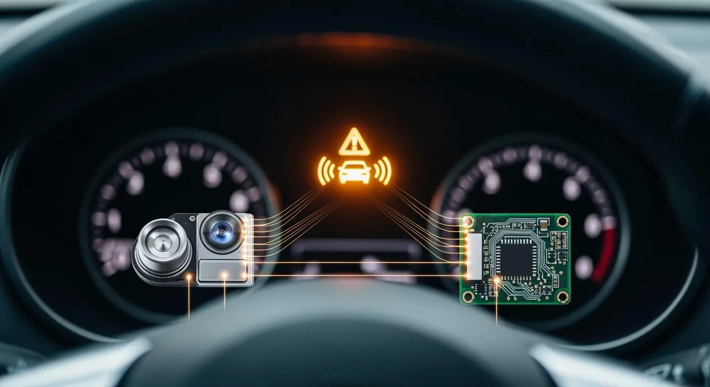
Automotive Electronics
Modern cars are packed with sensitive electronics for infotainment, safety systems (like ADAS), and engine control. These systems require a very stable power supply to function reliably. However, a car's electrical system is a harsh environment. A "cold crank," where you start the engine in cold weather, can cause the battery voltage to drop significantly.
Problem Solved: During a cold crank, a 12V battery's voltage can dip far below its normal level. A buck-boost converter ensures that a critical component, like an infotainment screen needing 5V, receives uninterrupted power. It boosts the low input voltage, preventing glitches or shutdowns.
This application makes the buck-boost converter a key component for automotive reliability. It provides a clean and steady power supply, protecting electronics from voltage sags and surges. As a HiSilicon authorized solutions partner, Nova Technology Company (HK) Limited is deeply involved in designing and providing such advanced power management solutions, including the versatile boost converter, for today's complex electronics.
You now see how a buck-boost converter is essential for modern electronics. This versatile dc to dc converter provides a stable power supply from a fluctuating input. Its ability to function as both a buck and boost converter makes it invaluable. From your smartphone to large solar farms, the buck boost step up converter ensures reliable and efficient power management.
Key Takeaway: The buck-boost converter's unique flexibility makes it a fundamental building block. It guarantees that your devices receive the steady power they need to perform at their best, no matter the source.
FAQ
What is the main difference between buck, boost, and buck-boost converters?
A buck converter only steps voltage down. A boost converter only steps voltage up. A buck-boost converter gives you the flexibility to do both. It can produce a stable output voltage that is higher, lower, or the same as the input voltage.
Why do some buck-boost converters have a negative output voltage?
The simplest buck-boost design naturally inverts the voltage polarity. This means if you input a positive voltage, you get a negative output. Modern 4-switch designs, however, can provide a non-inverted positive output, which is more useful for most electronics.
What does "duty cycle" mean in a converter?
You can think of the duty cycle as the switch's "on-time". It is the percentage of time the switch is on during one full cycle. The controller adjusts this percentage to regulate the output voltage, storing more or less energy in the inductor.
Quick Tip 💡 A higher duty cycle generally leads to a higher output voltage in boost or buck-boost mode.
Can a buck-boost converter work if the input and output voltages are the same?
Yes, it can. This is a key advantage. When your input voltage is very close to your desired output voltage, the converter operates in a special buck-boost region. It ensures a smooth, stable output without any glitches during the transition.