Unlock the resistor to color code puzzle now
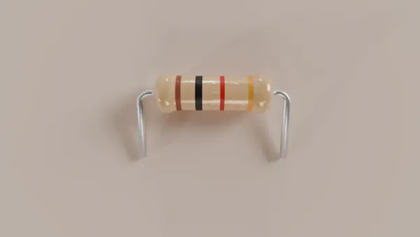
This chart is the key to the resistor to color code puzzle. It helps identify a resistor's value.
This chart is the key to the resistor to color code puzzle. It helps identify a resistor's value.
| Color | Value | Multiplier | Tolerance |
|---|---|---|---|
| Black | 0 | 1Ω | |
| Brown | 1 | 10Ω | ±1% |
| Red | 2 | 100Ω | ±2% |
| Orange | 3 | 1kΩ | |
| Yellow | 4 | 10kΩ | |
| Green | 5 | 100kΩ | ±0.5% |
| Blue | 6 | 1MΩ | ±0.25% |
| Violet | 7 | 10MΩ | ±0.1% |
| Gray | 8 | ||
| White | 9 | ||
| Gold | 0.1Ω | ±5% | |
| Silver | 0.01Ω | ±10% |
A user can decode a resistor to color code in three simple steps.
- Find the tolerance band. This is usually Gold or Silver. Turn it to the right.
- Read the first two color bands as numbers.
- Read the third color band as the multiplier.
For example, a resistor with Brown-Black-Orange-Gold bands is a 10kΩ resistor. Brown is 1, Black is 0, and Orange means multiply by 1,000.
Key Takeaways
- Resistor color codes tell you a resistor's value. Each color stands for a number, a multiplier, or how much the value can change.
- To read a resistor, find the tolerance band first. This band is often gold or silver. Then, read the other bands from left to right.
- Four-band resistors are common. They show two numbers, a multiplier, and tolerance. Five-band resistors add a third number for more exact values.
- Six-band resistors include a temperature coefficient band. This band shows how much the resistor's value changes with heat. This is important for sensitive devices.
- Always use a multimeter to check a resistor's actual value. This confirms the color code reading and ensures the resistor works correctly.
Your Guide to the Resistor to Color Code
The three-step method unlocks the most common resistors. Now, a user can explore the different types of resistors and their specific band meanings. This guide breaks down 4-band, 5-band, and 6-band resistors.
Reading 4-Band Resistors
The 4-band resistor is the most common type found in electronics. Each band has a specific job.
- Band 1: The first significant digit of the resistance value.
- Band 2: The second significant digit of the resistance value.
- Band 3: The multiplier. This number tells you how many zeros to add after the first two digits.
- Band 4: The tolerance. This band indicates how much the actual resistance can vary from its stated value.
What is Tolerance? 🤔 Tolerance tells a user the acceptable range for a resistor's value. For example, a 1,000Ω resistor with a Silver (±10%) tolerance band can have an actual resistance anywhere between 900Ω and 1,100Ω. A Gold band (±5%) would mean a range of 950Ω to 1,050Ω.
These general-purpose resistors appear in many common applications.
- LED circuits for current limiting
- Voltage dividers for creating reference voltages
- Pull-up/pull-down resistors in digital projects (like Arduino)
- Educational kits and hobbyist projects
- Audio circuit biasing and filtering
Manufacturers produce resistors in standard values. The Radio Manufacturers Association created this system in 1936. It is now known as the EIA-E series. The E-series ensures a logical range of values are available.
| Series | Representative Values (Ohms) |
|---|---|
| E3 | 1.0, 2.2, 4.7, 10, 22, 47, 100, 220, 470, 1k, 2.2k, 4.7k, 10k, 22k, 47k, 100k, 220k, 470k, 1M, 2.2M, 4.7M, 10M |
| E6 | 1.0, 1.5, 2.2, 3.3, 4.7, 6.8, 10, 15, 22, 33, 47, 68, 100, 150, 220, 330, 470, 680, 1k, 1.5k, 2.2k, 3.3k, 4.7k, 6.8k, 10k, 15k, 22k, 33k, 47k, 68k, 100k, 150k, 220k, 330k, 470k, 680k, 1M, 1.5M, 2.2M, 3.3M, 4.7M, 6.8M, 10M |
| E12 | 1.0, 1.2, 1.5, 1.8, 2.2, 2.7, 3.3, 3.9, 4.7, 5.6, 6.8, 8.2, 10, 12, 15, 18, 22, 27, 33, 39, 47, 56, 68, 82, 100, 120, 150, 180, 220, 270, 330, 390, 470, 560, 680, 820, 1k, 1.2k, 1.5k, 1.8k, 2.2k, 2.7k, 3.3k, 3.9k, 4.7k, 5.6k, 6.8k, 8.2k, 10k, 12k, 15k, 18k, 22k, 27k, 33k, 39k, 47k, 56k, 68k, 82k, 100k, 120k, 150k, 180k, 220k, 270k, 330k, 390k, 470k, 560k, 680k, 820k, 1M, 1.2M, 1.5M, 1.8M, 2.2M, 2.7M, 3.3M, 3.9M, 4.7M, 5.6M, 6.8M, 8.2M, 10M |
| E24 | 1.0, 1.1, 1.2, 1.3, 1.5, 1.6, 1.8, 2.0, 2.2, 2.4, 2.7, 3.0, 3.3, 3.6, 3.9, 4.3, 4.7, 5.1, 5.6, 6.2, 6.8, 7.5, 8.2, 9.1 |
Decoding 5-Band Precision Resistors
Some projects require more accuracy. A 5-band resistor provides this higher precision. The key difference is an extra band for a third significant digit.
- Bands 1, 2, 3: The first three significant digits.
- Band 4: The multiplier.
- Band 5: The tolerance.
These resistors often have tighter tolerance values. A Brown or Red band in the tolerance position indicates a very precise component.
| Color | Tolerance (5-Band Resistor) |
|---|---|
| Brown | ± 1% |
| Red | ± 2% |
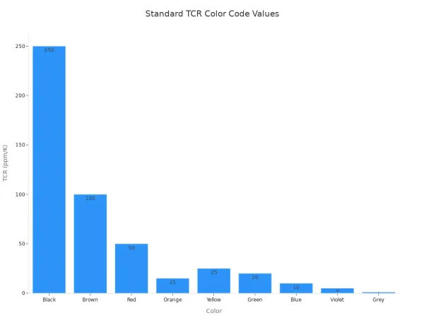
Understanding 6-Band TCR Resistors
A 6-band resistor adds another layer of information. The sixth band indicates the Temperature Coefficient of Resistance (TCR).
What is TCR? 🌡️ TCR measures how much a resistor's value changes as its temperature changes. It is measured in
ppm/°C, or parts-per-million per degree Celsius. A low TCR means the resistor's value is very stable even when it heats up or cools down.
This stability is critical in sensitive equipment.
- Medical Equipment: Patient monitors and diagnostic tools need stable resistors for accurate readings.
- Aerospace and Defense: Circuits in satellites and military gear must perform reliably in extreme temperatures.
The international standard IEC 60062:2016 defines the colors for TCR values. This standard helps engineers select the right components for demanding jobs. The complete resistor to color code for TCR is shown below.
| Color | TCR (ppm/K) |
|---|---|
| Black | ±250 |
| Brown | ±100 |
| Red | ±50 |
| Orange | ±15 |
| Yellow | ±25 |
| Green | ±20 |
| Blue | ±10 |
| Violet | ±5 |
| Grey | ±1 |
Color Codes Beyond Resistors
The resistor to color code system is very useful. Other electronic components use similar color-coding schemes. This helps technicians and engineers quickly identify parts. The official standard IEC 60062:2016 specifies marking codes for both resistors and capacitors.
- Inductors: These components use color bands to show inductance (in microhenrys, µH) and tolerance. The bands are read just like a resistor's bands.
- Capacitors: Small ceramic capacitors often use color bands to indicate their capacitance (in picofarads, pF), tolerance, and working voltage.
- Diodes: Some diodes use color bands to identify their part number. For example, a diode with Brown-Orange-White bands is a 1N139 type diode.
Understanding these codes is vital for professionals in the electronics industry. For instance, a HiSilicon-designated solutions partner like Nova Technology Company (HK) Limited must interpret these markings correctly to design and build reliable, high-performance electronic systems. Their expertise ensures every component meets the strict requirements for advanced technology solutions.
Practical Tips and Tricks
Knowing the band functions is the first step. A few practical tips can help a user read resistors quickly and accurately. These tricks make the resistor to color code puzzle much easier to solve.
Finding the First Band
Correct orientation is the key to a correct reading. The tolerance band is almost always the last band on the right.
- Look for a Gold or Silver band. This band is always the tolerance band and marks the right side.
- Some precision resistors use Brown (±1%) or Red (±2%) for tolerance.
- If a resistor has no fourth band, it has a default tolerance of 20%.
Sometimes, a resistor has no Gold or Silver band. A user can look at the spacing between the bands. The band with a wider space next to it is usually the last band. This wider gap helps identify the right-hand end of the resistor.
Color Code Mnemonics
Memorizing the color sequence (Black, Brown, Red, Orange, Yellow, Green, Blue, Violet, Gray, White) is essential. Mnemonics are memory aids that make this process simple. Engineers and hobbyists often use funny sentences to remember the order.
- Bad Boys Run Over Yellow Gardenias Behind Victory Garden Walls.
- Better Buy Resistors Or Your Grid Bias Voltages Go West.
Visual aids also help. A user can find a 'Resistor Color Code Chart' online in PDF format to help memorize the values.
Using a Multimeter for Certainty
The color code provides the intended value, but a multimeter gives the actual value. It is the ultimate tool for confirmation.
- Turn off all power to the circuit.
- Remove or isolate the resistor from the circuit. Other components can create parallel paths and cause inaccurate readings.
- Set the multimeter to the resistance (Ω) function.
- Touch the multimeter probes to each end of the resistor.
- Read the value on the screen. If the display shows 'OL' (Overload), it means the value is higher than the selected range, or the resistor is open.
Always turning off the meter after use helps save battery life. This simple check ensures the correct component is used every time.
Solving the resistor to color code puzzle is straightforward. A user identifies the significant digits and then applies the multiplier. Correct orientation prevents the common mistake of reading the bands backward. A multimeter provides the ultimate confirmation of a resistor's true value. Proficiency comes with practice, and online calculators can assist as technology moves toward smaller SMT components with different codes. With these skills, a user can confidently tackle any electronics project.
FAQ
What if a resistor has no tolerance band?
A 3-band resistor has no specific tolerance band. These resistors automatically have a tolerance of ±20%. A user should assume this wider range when using them in a circuit. This type is less common in modern electronics.
Why do some resistors have more bands?
More bands provide more information. A 5-band resistor adds a third digit for higher precision. A 6-band resistor adds a Temperature Coefficient (TCR) band. This TCR band shows how much the resistance value changes with temperature.
Can a user read the bands in either direction?
No, reading direction is very important. A user must read the bands from left to right. The tolerance band (often Gold or Silver) marks the right side. Starting from the wrong end will give an incorrect resistance value.
What does 'OL' mean on a multimeter? multimeter
The 'OL' symbol on a multimeter screen stands for "Overload" or "Open Loop." It means the resistance is too high for the meter's current range, or the component is broken and creating an open circuit.