A Practical Guide to Type C vs USB C for Engineers
You often face the 'type c vs usb c' question in design projects. The answer is simple. USB Type-C defines the phy
You often face the 'type c vs usb c' question in design projects. The answer is simple. USB Type-C defines the physical, reversible connector. In contrast, "USB-C" colloquially describes the various USB standards this usb-c connector supports.
Note: The connector itself does not guarantee performance; the underlying USB protocol does.
The rapid adoption of this USB standard makes understanding it critical. Market forecasts show significant growth for this USB technology:
| Report Source | Forecast Period | CAGR |
|---|---|---|
| Credence Research | 2025-2032 | 13.53% |
| Report Source | Forecast Period | CAGR |
|---|---|---|
| Research Nester | 2025-2037 | 24.6% |
This practical guide helps you navigate the specifications of the USB Type-C connector and its associated USB-C protocols for successful system integration.
Key Takeaways
- USB Type-C is the physical connector. USB-C describes the data and power standards it uses.
- The USB Type-C connector has 24 pins. This allows for high-speed data, power, and video.
- Not all USB Type-C ports are the same. Some have fewer pins and support fewer features.
- USB Power Delivery (PD) allows for fast charging. It can deliver up to 240 watts of power.
- Alternate Modes (Alt Modes) let USB Type-C carry video signals. This sends video to monitors.
The Core Difference: Type C vs USB C
The debate over type c vs usb c often starts with the hardware. You must first understand the physical connector before analyzing the protocols it supports. The USB Type-C connector is a marvel of engineering, designed for both durability and high performance. Its capabilities, however, are defined by the electronics behind it. This section breaks down the physical design of the usb connector system.
Physical Design of the USB Type C Connector
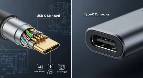
You can immediately recognize the USB Type-C connector by its small, symmetrical shape. With physical dimensions of just 8.4mm by 2.6mm, it is almost as small as a Micro-USB or Apple's Lightning connector. This compact form factor makes it ideal for modern slim devices.
Its most celebrated feature is reversibility. You can insert the cable in either orientation, eliminating the frustration common with older USB-A connectors. This user-friendly design is a key reason for its widespread adoption. However, the physical connector is only half the story in the type c vs usb c discussion; its internal pinout is where the true complexity lies.
The 24-Pin Layout and Signal Integrity
The magic of the USB Type-C connector is in its 24-pin configuration. This intricate layout supports everything from high-speed data to power and video. The design uses redundant pins to make reversibility possible. For example, the receptacle has two sets of high-speed data lanes. The Configuration Channel (CC) pins detect the cable's orientation and tell the system which lanes to activate. This ensures a proper connection every time you plug in a usb cable.
For your engineering designs, maintaining signal integrity across these pins is critical, especially for high-speed protocols. Poor layout can lead to data errors, reduced performance, or complete connection failure.
Design Tip: For SuperSpeed USB data (5 Gbps and higher), you must strictly control impedance and differential pair lengths.
Follow these essential guidelines for your PCB layout:
- Impedance Control: Route all high-speed TX/RX pairs as controlled-impedance differential pairs. You should target 90Ω for the entire trace length.
- Length Matching: Keep the two traces within each differential pair precisely length-matched. A common target is less than 5 ps of skew per inch to prevent timing issues.
- Minimize Discontinuities: Avoid using vias on high-speed traces. If a via is necessary, design it carefully with adjacent ground stitching to maintain a continuous return path.
- Noise Reduction: Place a common-mode choke on SuperSpeed pairs near the usb-c connector. This helps reduce radiated noise without significant signal loss.
Connector Variants and Pin Counts
A common pitfall is assuming every USB Type-C port offers the same features. Manufacturers can create cost-effective versions of the usb connector system by using fewer pins. These variants support basic functions like charging and USB 2.0 data but lack the pins for high-speed transfer or video.
This is why you must always verify the pinout in component datasheets. A full-featured usb cable will not grant high-speed capabilities to a device equipped with a limited-pin connector. The table below shows the key differences between a full-featured usb connector and a USB 2.0-only variant.
| Feature | Full-Featured 24-Pin USB Type-C | USB 2.0-Only Type-C |
|---|---|---|
| Total Pins | 24 | 16 or fewer |
| High-Speed Data | Yes (USB 3.x, USB4) | No |
| Video Transmission | Yes (Alternate Modes) | No |
| Fast Charging | Yes (USB Power Delivery) | Yes (Basic VBus/GND/CC) |
| Omitted Pins | None | High-speed TX/RX and SBU pins |
Understanding these physical differences in the usb connector system is the first step. It helps you select the right components and avoid costly design errors related to the usb cable and connector. The next section will explore the protocols that this versatile usb hardware enables.
A Deep Dive into USB-C Protocols

The physical USB Type-C connector is the foundation, but the protocols are what bring it to life. Before any data flows or high-power charging begins, a negotiation happens over the Configuration Channel (CC) pins. Think of the CC line as the brain of the connection. It determines which device is the host, how much power can be delivered, and whether a special protocol like DisplayPort should be activated. This negotiation unlocks the true potential of the USB Type-C connector. Understanding these protocols is essential for your designs.
Data Transfer: USB 3.2, USB4, and Thunderbolt
The USB Type-C connector supports several data protocols, each offering different levels of performance. Your choice of protocol directly impacts the device's capabilities for fast data transfers.
The USB Implementers Forum (USB-IF) manages the USB specifications. The USB4 standard represents a major leap forward by integrating the Thunderbolt 3 protocol. This convergence provides a more unified and capable ecosystem. You can see the maximum theoretical transfer rate for key protocols below.
| Technology | Maximum Theoretical Data Transfer Speed |
|---|---|
| USB 3.2 Gen 2x2 | 20 Gbps |
| USB4 Gen 3x2 | 40 Gbps |
| Thunderbolt 4 | Up to 40 Gbps |
This impressive speed is not just about bandwidth; it also depends on sophisticated encoding schemes. For instance, USB4 uses 128b/132b encoding, which is highly efficient for transmitting data. The newer USB4 Version 2.0 standard pushes this further by using PAM3 (Pulse Amplitude Modulation with 3 levels). This advanced encoding enables an incredible 80 Gbps transfer rate over the same passive 40 Gbps USB cable.
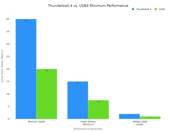
While USB4 sets a powerful baseline, Thunderbolt 4 offers a certified guarantee of performance. Intel's certification for Thunderbolt 4 ensures that any port or device meets strict minimum requirements. For high-performance applications, this predictability is invaluable. USB4, by contrast, allows manufacturers more flexibility, which can lead to performance variations.
Key Takeaway: Thunderbolt 4 is a premium implementation of the USB4 specification. It guarantees features that are optional for a standard USB4 port, such as support for two 4K displays and a minimum data transfer rate of 40 Gbps.
Power Delivery (PD) and Power Data Objects (PDOs)
The USB Type-C connector revolutionizes device charging with the USB Power Delivery (PD) specification. This protocol allows for significantly higher power levels than the old USB standards. The entire process begins on the CC line. A device acting as a power source uses a pull-up resistor (Rp), while a power sink uses a pull-down resistor (Rd). The value of the Rp resistor advertises the source's initial current capability.
| Rp Resistance Value | Advertised Supply Capability |
|---|---|
| 56kΩ pull-up | Default USB Power |
| 22kΩ pull-up | 1.5A |
| 10kΩ pull-up | 3.0A |
This initial handshake only establishes basic power. For advanced charging, a full USB PD negotiation is required. This complex communication happens exclusively over a USB-C to USB-C connection. During this negotiation, devices exchange information using Power Data Objects (PDOs).
The power negotiation follows a clear sequence:
- The source (e.g., a charger) sends a list of its capabilities, detailed in one or more PDOs. These PDOs can be for fixed voltages (5V, 9V), variable voltages, or batteries.
- The sink (e.g., a laptop) reviews the list and sends a request for a specific PDO that meets its charging needs.
- The source accepts the request and prepares to supply the new voltage and current.
- Finally, the source sends a
PS_RDY(Power Supply Ready) message, and the sink begins drawing the higher power.
The latest USB PD 3.1 specification introduced the Extended Power Range (EPR), pushing the maximum power delivery from 100W up to 240W. This enables the USB-C connector to power even the most demanding devices, like gaming laptops and large monitors.
| Voltage | Current | Power Level |
|---|---|---|
| 28V | 5A | 140W |
| 36V | 5A | 180W |
| 48V | 5A | 240W |
Alternate Modes (Alt Modes) for Video and Data
One of the most powerful features of USB Type-C is its ability to carry non-USB protocols. This is achieved through Alternate Modes (Alt Modes). When an Alt Mode is active, the high-speed data lanes in the USB cable are reconfigured to carry other types of signals, most commonly video.
You have flexibility in how you allocate these lanes. For example, you can configure the connection to use:
- Two lanes for video and two lanes for USB 3.x data. This is a common configuration that allows you to output 4K video while maintaining a high-speed USB data connection.
- All four lanes for video. This maximizes video bandwidth for the highest resolutions and refresh rates. In this mode, data transfer falls back to the separate USB 2.0 pins.
The most widely used Alt Mode is DisplayPort. The latest DisplayPort Alt Mode 2.0 specification is fully integrated with the USB4 standard. It can drive a single 16K display or two 8K displays over a single USB Type-C cable. Other Alt Modes also exist, such as MHL (Mobile High-Definition Link), though they are less common today. Your system's controller IC must support a specific Alt Mode for it to function.
Engineering and Design Considerations
Navigating the complexities of USB-C requires more than just understanding the standards; it demands careful engineering and design choices. A single oversight can lead to performance issues, compatibility problems, or even product failure. This section covers common pitfalls, component selection, and how to verify specifications to ensure your design is robust and reliable.
Common Implementation Pitfalls
The flexibility of the USB Type-C connector is one of its greatest strengths, but it also introduces potential for error. A common mistake is improper PCB layout. High-speed data lines, like those for USB4, require precise impedance control and minimal signal degradation.
- Mismatched Impedance: Failing to maintain a consistent 90Ω differential impedance can cause signal reflections and data errors.
- Signal Crosstalk: Routing high-speed traces too close to each other or without proper ground plane shielding can lead to interference.
- Poor Power Integrity: Inadequate power delivery design can introduce noise and instability, affecting both data and power functions.
These design flaws have real-world consequences. For example, a popular portable monitor experienced constant disconnections because its power delivery circuit violated USB-PD specifications, creating state corruption issues. Similarly, even major manufacturers can make mistakes; Apple's A1882 30W charger had a firmware bug that made it incompatible with certain USB-IF compliant devices, highlighting the importance of thorough testing. These examples underscore the disadvantages of poor implementation.
Component Selection: Cables, Controllers, and Receptacles
Choosing the right components is critical for a successful USB-C implementation. Your selection of the cable, controller IC, and physical connector will define the final capabilities of your product.
Cables: Not all USB-C cables are created equal. They vary in data speed, power delivery, and support for Alternate Modes. A key distinction is between passive and active cables.
| Feature | Passive Cable | Active Cable |
|---|---|---|
| Length | Shorter (typically < 2m for high speed) | Longer (up to 5m or more) |
| Cost | Lower | Higher |
| Electronics | None | Contains re-driver/re-timer chips |
| Use Case | General purpose, short-distance connections | Long-distance connections, high-speed data |
Controllers and Receptacles: The controller IC is the brain of the USB-C port, managing everything from power negotiation to data routing. When designing complex systems, especially those involving high-speed data and multiple protocols, partnering with a specialist can be invaluable. For instance, Nova Technology Company (HK) Limited, a HiSilicon-authorized solutions partner, provides deep expertise in chip-level solutions and system integration, helping navigate the intricacies of advanced USB-C designs.
Finally, ensure the physical USB Type-C connector you choose has the necessary pins for your application. A 16-pin connector, for example, will not support SuperSpeed USB data or DisplayPort Alt Mode, regardless of the controller's capabilities.
| Standard | Max Data Speed | Max Power Delivery | Video Support |
|---|---|---|---|
| USB 3.2 Gen 1 | 5 Gbps | 100W (with PD) | DP Alt Mode |
| USB 3.2 Gen 2 | 10 Gbps | 100W (with PD) | DP Alt Mode |
| USB 3.2 Gen 2x2 | 20 Gbps | 100W (with PD) | DP Alt Mode |
| USB4 | 40 Gbps | 240W (with EPR) | DP Alt Mode 2.0 |
| Thunderbolt 4 | 40 Gbps | 100W (240W with EPR) | DP Alt Mode 2.0 |
Verifying Specifications in Datasheets
Trusting marketing claims is a significant risk. You must always verify specifications by reading the component datasheets. This is the only way to confirm true capabilities and ensure system-wide compatibility.
When reviewing a datasheet for a device or cable, look for:
- Explicit Mentions: Search for terms like "USB4," "Thunderbolt 4," or "DisplayPort Alt Mode." The absence of these terms often means the feature is not supported.
- Logos and Symbols: The official USB-IF and Thunderbolt logos are reliable indicators of certified performance. A simple USB trident logo on a USB Type-C port often means it only supports USB 2.0 speeds.
- Power Delivery Details: For power-related components, check for Power Data Object (PDO) profiles. A datasheet for a power adapter should list the specific voltage and current combinations it can supply. You can use a tool like a USBHub3c to read a cable's e-marker chip and verify its advertised power and data capabilities.
Understanding the advantages and disadvantages of each specification is crucial. The primary advantages of higher-spec components are speed and functionality, but the disadvantages include increased cost and design complexity. For many modern electronics, from laptops to peripherals, a full-featured USB Type-C port is essential, but for simpler devices, a more basic implementation may be sufficient. Carefully analyzing datasheets ensures you select the right components for your application, avoiding the disadvantages of over-engineering or the pitfalls of under-speccing your design. The advantages of this diligence are a reliable product and a satisfied end-user.
You now understand the core of the type c vs usb c distinction. The USB Type-C connector is the physical "how," while the usb standards define the performance "what." Your design success depends on matching the right usb protocol with the right hardware. To prevent costly errors in the type c vs usb c landscape, you must meticulously verify specifications.
Pro Tip: Always check for official usb certification. Before testing, manufacturers must submit a Vendor Information File (VIF) detailing the product's usb capabilities. You should look for this data to confirm performance claims.
FAQ
What is the main difference between Type C and USB C?
You can think of it this way: USB Type-C is the physical connector shape. "USB-C" is the common term for the various data and power standards (like USB4 or Power Delivery) that the connector can support. The connector is the "how," and the standard is the "what."
Do all USB Type-C ports support fast charging?
No, they do not. A port must support the USB Power Delivery (PD) protocol for fast charging. Without PD, a Type-C port only provides basic power. You must always check the device's datasheet to confirm its power capabilities.
Can I connect any USB Type-C port to a monitor?
No, video output requires a feature called Alternate Mode (Alt Mode). Your device's port and controller must specifically support a video protocol like DisplayPort Alt Mode. A standard data-only or power-only port will not transmit a video signal.
Is USB4 the same as Thunderbolt 4? ⚡
They are closely related but not identical. Thunderbolt 4 is a premium, certified version of the USB4 specification. It guarantees top-tier features like 40 Gbps speed and support for dual 4K displays, which are optional for a standard USB4 port.