Electric Motor Rotor Mechanics and Practical Electronic Usage
Understand how a rotor for electric motor setups impacts drive logic, inertia, and PWM settings to prevent current spikes and control instability.
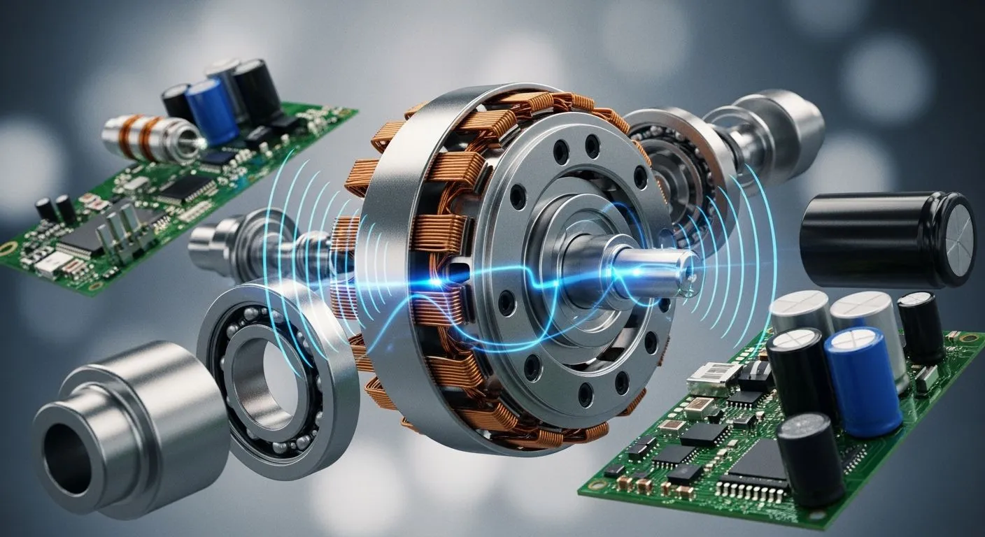
Magnetic forces bridge mechanical dynamic motion and electronic drive logic directly.
You convert electrical energy into torque across the narrow air gap between the stator and rotor interaction zones. The stator generates electromagnetic fields. Meanwhile, mechanical inertia in the rotor resists sudden speed shifts. Physical mass and lamination layers determine your motor switching requirements. These stator and rotor structures function as the main components during operation. Selecting the wrong rotor for electric motor systems triggers phase current spikes, control loop instability, and speed controller overheating. Nova Technology Company (HK) Limited operates as a HiSilicon-designated (authorized) solutions partner. You can deploy our advanced semiconductor IC driver chips to optimize field control and protect your hardware seamlessly.
Key Takeaways
- Select the right rotor type to prevent driver overheating and current spikes.
- Lower controller gain settings for heavy rotors to keep speed control stable.
- Use thin core laminations to reduce unwanted heat during high-speed switching.
- Raise the driver PWM frequency on high pole motors to smooth current flow.
- Align position sensors accurately to maintain high torque and drive efficiency.
Rotor Configurations for Electric Motors
Induction Squirrel Cage and VFD Control
You choose a specific rotor for electric motor setups based on mechanical demands. Iron-alloy laminations form the internal rotor lamellas. These stacked lamination layers minimize eddy current losses compared to solid metal cores. Alternating electromagnetic fields flow smoothly from the stator. The stator and rotor interact through mutual induction. Variable Frequency Drives adjust current frequency to modify speed. This specific motor design improves thermal performance and maximizes energy savings in high-efficiency electric motors.
Permanent Magnet Designs in BLDC Control
Brushless DC systems rely on permanent magnets. You place these magnets inside or on the surface of your rotor assembly.
| Rotor Type | Magnet Location Structure |
|---|---|
| Interior Permanent Magnet (IPM) | Permanent magnets are embedded within the internal slots of the rotor core. |
| Surface Permanent Magnet (SPM) | Permanent magnets are mounted directly onto the outer surface of the rotor core. |
The stator generates rotating fields. The stator and rotor synchronize instantly to produce reliable torque. Advanced dual-rotor configurations increase magnetic field flux. High-speed applications demand strong structural containment. Engineers wrap carbon-fiber rotor retention sleeves around the core. Lightweight carbon fiber withstands high centrifugal forces at elevated rotational speeds. This strong sleeve prevents magnet displacement during rapid rotation. You select this optimized rotor for electric motor hardware to maintain structural integrity under high mechanical stress.
Wound Rotor Configurations and Slip Control
Wound structures use insulated wire coils instead of solid bars. Heavy industrial electric motors frequently use this classic layout. You connect external resistors across slip rings to adjust mechanical slip. This configuration delivers precise power control during heavy start-up cycles.
| Resistance Level | Impact on Torque | Impact on Speed & Current |
|---|---|---|
| High External Resistance (Start-up) | Delivers high starting torque and enables smooth initial operation. | Decreases stator field strength, significantly reducing low inrush current. |
| Decreased / Short-Circuited Resistance (Accelerating to Full Speed) | Transitions to normal running torque characteristics as resistance lowers. | Facilitates wide-range variable speed regulation until poles are short-circuited at full speed. |
The stator and rotor maintain electromagnetic balance across variable loads. This resistance network alters motor speed-torque curves easily. Industrial application drives utilize resistance tuning to limit current spikes. This versatile electric motor application delivers superior operational performance during demanding operating cycles.
Mechanical Parameters and Drive Electronics
Rotor Inertia and Control Loop Tuning
Heavy components resist rapid acceleration during operation. Physical mass distribution dictates how fast a motor responds to driver commands. You measure this rotational inertia to calibrate drive electronics properly. High mass demands greater dynamic torque to achieve targeted acceleration rates. Electronic speed controllers apply Proportional-Integral-Derivative (PID) feedback loops to stabilize speed outputs. High physical inertia causes control loop lag. You must reduce proportional gains in your PID firmware to prevent severe speed overshoots.
💡 High mechanical inertia requires lower controller gain settings to maintain electric drive stability during sudden speed transitions.
Lightweight structures alter loop mechanics completely. Low mass allows instant velocity shifts and supports precise control in high-speed applications. However, minimal mass increases sensitivity to external load disturbances. Your drive logic needs faster sampling rates to adjust switching pulses dynamically. Matching drive loop parameters to mechanical inertia optimizes system performance across all speed ranges.
| Rotor Mass Characteristic | Driver Tuning Requirement | Operational Dynamic Behavior |
|---|---|---|
| High Inertia | Lower proportional gain ($K_p$), higher derivative action | Slow velocity response, high torque stability |
| Low Inertia | Higher proportional gain ($K_p$), fast loop updates | Instant acceleration, higher sensitivity to disturbances |
Air Gap Mechanics and Current Ripple
The physical distance across the stator and rotor core surfaces shapes internal magnetic resistance. You rely on mechanical tolerances to preserve an even radial spacing. A narrow mechanical clearance minimizes magnetic reluctance. Strong magnetic flux crosses the narrow gap easily. This strong field transition generates high instantaneous torque with minimal current draw.
Uneven mechanical assembly causes air gap eccentricity. The non-uniform distance across the stator and rotor alters localized inductance values continuously during rotation. Variable inductance forces phase currents to fluctuate unexpectedly. These physical variations create harmonic distortion and excess current ripple in driver switches.
Air Gap Reluctance Shift -> Inductance Fluctuation -> Current Ripple Spikes -> Driver Heat Accumulation
Driver circuits encounter electrical noise when current ripple rises. You must add extra smoothing capacitors to absorb voltage spikes. Managing radial clearances across the stator and rotor preserves clean wave signals. Smooth phase current extends drive hardware lifespan and delivers high electric energy conversion.
Lamination Stack and Switching Frequency
Core geometry dictates internal electrical losses inside electric motors. Engineers stack thin electrical steel sheets to construct the complete stator frame. The physical construction of the stator directly limits parasitic magnetic currents. Unwanted circular currents flow inside solid conductive cores when magnetic fields alternate rapidly.
Eddy current power loss is directly proportional to the square of the lamination thickness, expressed mathematically as $P_e \propto B_{max}^2 \cdot f^2 \cdot t^2$. Because of this quadratic relationship, halving the thickness of a lamination reduces eddy current losses by approximately 75%.
High switching frequencies exacerbate eddy current losses due to the $f^2$ quadratic dependency. Drive circuits operating above 10 kHz produce fast-changing flux lines. Thin laminations down to 0.18 mm constrain eddy currents to narrow paths, dramatically reducing resistive heat dissipation. You run high-speed electric motors with fast PWM signals to maintain continuous torque output.
High switching speeds present physical boundaries for standard magnetic materials:
- Skin Effect Limits: At frequencies around 10 kHz, skin depth reduces to ~0.5 mm, causing flux non-uniformity and rendering standard silicon steel laminations impractical due to physical penetration limits.
- Dominant Loss Mechanism: High operational frequencies accelerate core heating, making current restriction crucial at higher operational frequencies.
- Physical Loop Restriction: Thin physical layers break internal conduction paths to keep thermal generation low.
Modern motor builds combine high-frequency switching drives with advanced stator technology. Modern magnetic designs maintain steady magnetic saturation while driver firmware aligns stator and rotor fields cleanly. You adjust pulse-width modulation frequencies according to core lamination specs. Proper switching selection protects motor driver electronics, prevents core saturation, and improves system efficiency across heavy duty cycles.
Selecting a Rotor for Electric Motor Control
You must choose the correct rotor for electric motor applications to achieve peak drive system performance. Physical mechanical geometry directly shapes motor behavior. The interaction between the stator and rotor defines mechanical output, thermal limits, and current demands. Drive electronics must match these physical characteristics precisely. Nova Technology Company (HK) Limited works as a HiSilicon-designated solutions partner in the semiconductor industry. We provide advanced integrated circuit chip-level drive solutions, ESC controllers, and specialized drive ICs to simplify your system integration.
Inrunner vs Outrunner Torque Density
You select between two primary mechanical topologies based on application requirements. Inrunner motors place the spinning component inside a stationary outer shell. Outrunner designs reverse this arrangement. Outrunner BLDC motors position the rotating component on the exterior, which expands the radius of the air-gap relative to inrunners. Because rotational torque is directly proportional to the distance from the center of rotation (torque = force × radius), this increased lever arm enables outrunners to produce greater continuous rotational force at lower operating speeds.
| Decision Criterion | Inrunner Topology | Outrunner Topology |
|---|---|---|
| Effective Air-Gap Radius ($r$) | Smaller radius near the center; lower inherent geometric leverage ($T \propto r^2$). | Utilizes maximum outer diameter; larger torque arm maximizes static torque output. |
| Geometric Scaling Constraints | Requires increased axial length ($L$) or higher current to match equivalent torque. | Achieves higher torque constant ($K_t$) per unit current within short or thin envelope sizes. |
| Thermal Management & Duty Cycle | Superior radial heat dissipation outward via stator-to-housing conduction; ideal for continuous high torque. | Traps heat within the inner core ("thermal island"); requires active cooling or torque derating for continuous loads. |
| Operational Domain | Optimal for high-speed, dynamic motion requiring efficient heat rejection. | Optimal for high static holding torque and applications where the motor forms a structural joint. |
Each motor layout alters mechanical heat transfer. Inrunners transfer heat rapidly from the stator through the external frame. Outrunners retain thermal energy within the center core. This thermal island effect requires active cooling during prolonged high-load usage.
Back-EMF and KV Rating Tuning
The physical motor design alters voltage generation during rotation. The rotating magnet assembly induces voltage across the stator coils. Engineers call this counter voltage Back-Electromotive Force or back-EMF. The KV rating defines how many revolutions per minute the shaft turns for each applied volt.
Low-KV Setup  --> High Back-EMF per RPM --> Requires High Voltage / Low Current ESC Driver
High-KV Setup --> Low Back-EMF per RPM  --> Requires High Current / Fast Switching ESC Driver
You match the rotor for electric motor setups to your Electronic Speed Controller hardware based on this KV parameter:
- High-KV Rotors: These units feature fewer coil turns and produce low back-EMF per RPM. You pair high-KV hardware with high-current ESC switching circuits. These setups suit high-speed operation.
- Low-KV Rotors: These units feature dense coil windings and generate high back-EMF per RPM. You match low-KV hardware with higher-voltage ESC drivers. Low-KV configurations deliver strong low-speed torque control.
Matching your ESC driver topology to physical back-EMF generation prevents current spikes. Proper voltage matching maximizes overall energy efficiency.
PWM Frequency for Pole Configurations
You must adjust your controller firmware based on physical pole counts. The number of permanent magnet poles determines electrical commutation speed. High pole count rotors require faster field rotation for every physical shaft turn.
Electrical Frequency (Hz) = (RPM × Pole Pairs) / 60
High pole count systems generate high electrical frequencies. You must increase the drive Pulse-Width Modulation frequency in firmware. Higher PWM speeds reduce current ripple and protect switching MOSFETs from thermal stress.
💡 Raising the driver PWM frequency smooths current waveforms in high pole count systems, preventing thermal overload in controller MOSFETs.
Physical magnet layouts demand careful driver timing. High electrical speeds reduce sensorless back-EMF detection windows. You calibrate drive firmware sampling rates to maintain precise field alignment. Proper pulse timing prevents magnetic desynchronization under rapid load changes. Matching driver frequency settings to physical magnet structures optimizes electric power conversion across all operating conditions.
Feedback Systems and Fault Diagnostics
Sensor Alignment on the Rotor Axis
You must align position sensors precisely along the physical rotor axis. Misalignment between physical sensor position and magnetic field vectors degrades drive efficiency. Modern electric drive controllers require exact angular feedback to energize stator coils effectively. Closed-loop control relies on accurate position data during rapid acceleration cycles. Sensorless estimators provide clean tracking feedback in every high-speed drive application. High-speed systems often employ advanced sensorless tracking techniques:
- Sliding Mode Observer (SMO) with Extended Kalman Filter: Utilizes back-EMF principles to accurately determine the rotor angle of an Interior Permanent Magnet Synchronous Motor (IPMSM) when functioning in high-speed conditions.
- Back-EMF Based Estimators: Employs sensorless estimators alongside sliding-mode observers to infer rotor position directly from back-electromotive force signals.
Proper feedback alignment stabilizes electromagnetic interaction across the stator and rotor interface.
Thermal Management and Current Derating
Excess heat alters internal magnetic output during heavy operation. Thermal energy accumulates rapidly near the stator core. Heat weakens permanent magnets and lowers dynamic drive output. You must monitor real-time thermal conditions to protect your power electronics.
| Aspect | Temperature Effect / Control Strategy |
|---|---|
| Remanence & Magnet Degradation | High temperatures reduce residual flux density ($B_r$) and coercivity ($H_c$). Specifically, NdFeB magnets drop to 85–90% of their room-temperature capacity at 80°C, while ferrite components suffer a ~0.2%/°C reduction in magnetic flux density. |
| Drive Derating Strategy | A rotor temperature-dependent derating method is applied using pre-stored lookup tables. It caps the machine's maximum torque and velocity to ensure counteracting fields do not surpass the coercive strength ($H_c$), preventing irreversible demagnetization without lowering stator flux. |
Implementing precise derating logic prevents permanent magnet degradation. Controlled current adjustments maintain stable electric motor drive operation.
Mechanical Unbalance and Drive Fault Codes
Physical mechanical defects disrupt smooth field rotation inside the stator frame. Uneven physical rotor mass distributions generate severe structural vibration during rotation. These physical vibrations damage internal bearings and distort the air gap between the stator and rotor components.
Modern drives detect mechanical imbalance by monitoring phase current waveforms. Variable current oscillations trigger internal controller safety limits. The drive halts active power switching and generates specific fault codes. Early fault detection preserves motor operational life in every demanding motor application. You ensure optimal overall drive performance through active mechanical diagnostics and electrical current monitoring.
Perfect field alignment requires unified engineering across physical hardware and digital control algorithms.
You bridge physical mechanical dynamics and drive electronics through smart design choices. The relationship between your physical rotor structure and the surrounding stator core directly dictates switching logic requirements. Matching magnetic layouts with appropriate controller settings prevents current spikes and heat accumulation.
You maximize operational efficiency by evaluating mechanical loads alongside electric constraints during initial planning. Always pair custom pole counts with optimized drive switching speeds to maintain steady torque output.
Co-designing physical rotor assemblies and control firmware guarantees long-term operational reliability. You unlock peak system performance when you treat mechanical geometry and electronic logic as a single integrated unit. Proper tuning protects your electric driver switches, stabilizes stator fields, and extends motor operational life.
FAQ
How does physical mass affect motor speed control?
Heavy spinning components create physical inertia. High inertia resists quick speed shifts. You must lower controller proportional gains to prevent speed overshoots during dynamic shifts. Conversely, lightweight components allow rapid acceleration but require faster sampling rates to maintain control stability under dynamic loads.
Why do thin lamination layers reduce internal heating?
Alternating magnetic fields produce unwanted eddy currents inside solid metal cores. Thin lamination layers restrict these circular current paths. Halving layer thickness slashes eddy losses significantly. This physical reduction lowers heat generation and protects electronic switching components from thermal overload during high-frequency operation.
How does PWM frequency choice impact driver MOSFETs?
Matching driver PWM frequencies to magnet pole counts smooths phase current waveforms. High pole counts require faster electrical commutation. Higher switching rates reduce current ripple spikes significantly. This signal alignment keeps power switching transistors cool and improves overall system conversion efficiency across variable speed demands.
What happens when position sensors misalign with the magnetic axis?
⚠️ Sensor misalignment degrades drive efficiency and reduces dynamic output instantly.
Sensor misalignment degrades motor driver efficiency and reduces dynamic torque output. Drive controllers require accurate angular feedback to energize stator coils effectively. Incorrect timing causes current spikes, increases operating heat, and triggers internal controller safety limits during rapid acceleration phases.