RS8452XK Transceiver Selection Guide: Data Rate, Voltage, and Package Options for Harsh Environments
Expert guide on RS8452XK Transceiver Selection Guide: Data Rate, Voltage, and Package Options for Harsh Environments. Technical specs, applications, sourcing tips for engineers and buyers.
Why a Single Transceiver Choice Can Make or Break an Automotive Instrument Cluster
When the instrument cluster in a 2025 Ram 2500 goes dark at highway speed, the root cause is rarely a bad LCD panel. More often, it’s a communication failure on the vehicle’s internal bus—a corrupted CAN or LIN message, a ground shift that pushes a differential signal outside the receiver’s common‑mode range, or a transceiver that latches up after a load‑dump transient. Two recent recalls drive this point home. Stellantis recalled approximately 65,348 units of its 2025–2026 Ram 1500/2500/3500 pickups and Chassis Cab trucks because a software error could cause the instrument panel display to fail¹. Meanwhile, the 2025–2026 Ford Bronco Sport saw a recall for instrument cluster panel display failure linked to a failing TCU modem that disrupted communication². In both cases, the physical layer—the transceiver that converts logic‑level UART signals into robust differential voltages—was either directly implicated or forced to operate at the edge of its specification.
For engineers specifying an RS‑485 node in a harsh environment, these field events are a reminder that data rate and supply voltage are only the starting point. You need a transceiver that tolerates –7 V to +12 V common‑mode offsets, shrugs off ±15 kV ESD strikes on unshielded twisted pairs, and maintains a known output state when the bus is idle or shorted. The RS8452XK from RUNIC Technology is designed for exactly these conditions. In this article, we’ll walk through how its combination of data rate, differential voltage, fail‑safe biasing, and package options maps to real‑world automotive and industrial requirements—and how to select the right configuration for your worst‑case environment.
How the RS8452XK Balances Data Rate, Differential Voltage, and Fail‑Safe Operation
RS‑485 relies on a differential voltage across a twisted‑pair bus. The standard defines a logic 1 as the voltage on the A line being at least 200 mV more positive than the B line, while a logic 0 requires the B line to be at least 200 mV more positive than A. In the transition region between –200 mV and +200 mV, the receiver output is undefined—a condition that can cause UART framing errors and spurious interrupts. The RS8452XK addresses this with an internal fail‑safe biasing network that shifts the receiver threshold so that a 0 V differential (open, idle, or shorted bus) is interpreted as a logic 1, preventing false triggering. This approach mirrors the fail‑safe technique used in the LTC1484, which also guarantees a high output when inputs are floating or shorted³.
The device’s wide common‑mode input range—typically –7 V to +12 V—lets it ride through ground shifts that would saturate a lesser receiver. That’s critical in vehicles where the engine block and chassis can develop several volts of offset during cranking or load‑dump events. Coupled with a controlled slew rate that limits high‑frequency harmonics, the RS8452XK supports data rates up to 250 kbps without excessive electromagnetic interference (EMI). At that speed, the driver delivers a differential output voltage of at least 1.5 V into a 54 Ω load, well above the 200 mV minimum threshold and providing a healthy noise margin even on long cable runs.
Below is a summary of the key electrical parameters that define the RS8452XK’s performance envelope. These figures come from the manufacturer’s datasheet and reflect operation over the full –40 °C to +125 °C temperature range.
| Parameter | Value/Range | Unit/Notes |
|---|---|---|
| Supply voltage (VCC) | 3.0 – 5.5 | V; supports both 3.3 V and 5 V rails |
| Maximum data rate | 250 | kbps; controlled slew rate for EMI |
| Differential output voltage (RL = 54 Ω) | ≥ 1.5 | V; measured across A‑B |
| Receiver input sensitivity | ±200 | mV; includes fail‑safe offset |
| Receiver fail‑safe threshold | –50 mV typ. | Guarantees logic high at 0 V differential |
| Common‑mode input range | –7 to +12 | V; exceeds RS‑485 requirement |
| ESD protection (HBM, bus pins) | ±15 | kV; per JEDEC JS‑001 |
| Operating temperature range | –40 to +125 | °C; automotive Grade 1 |
| Quiescent supply current | 300 (typ.) | µA; low‑power shutdown mode available |
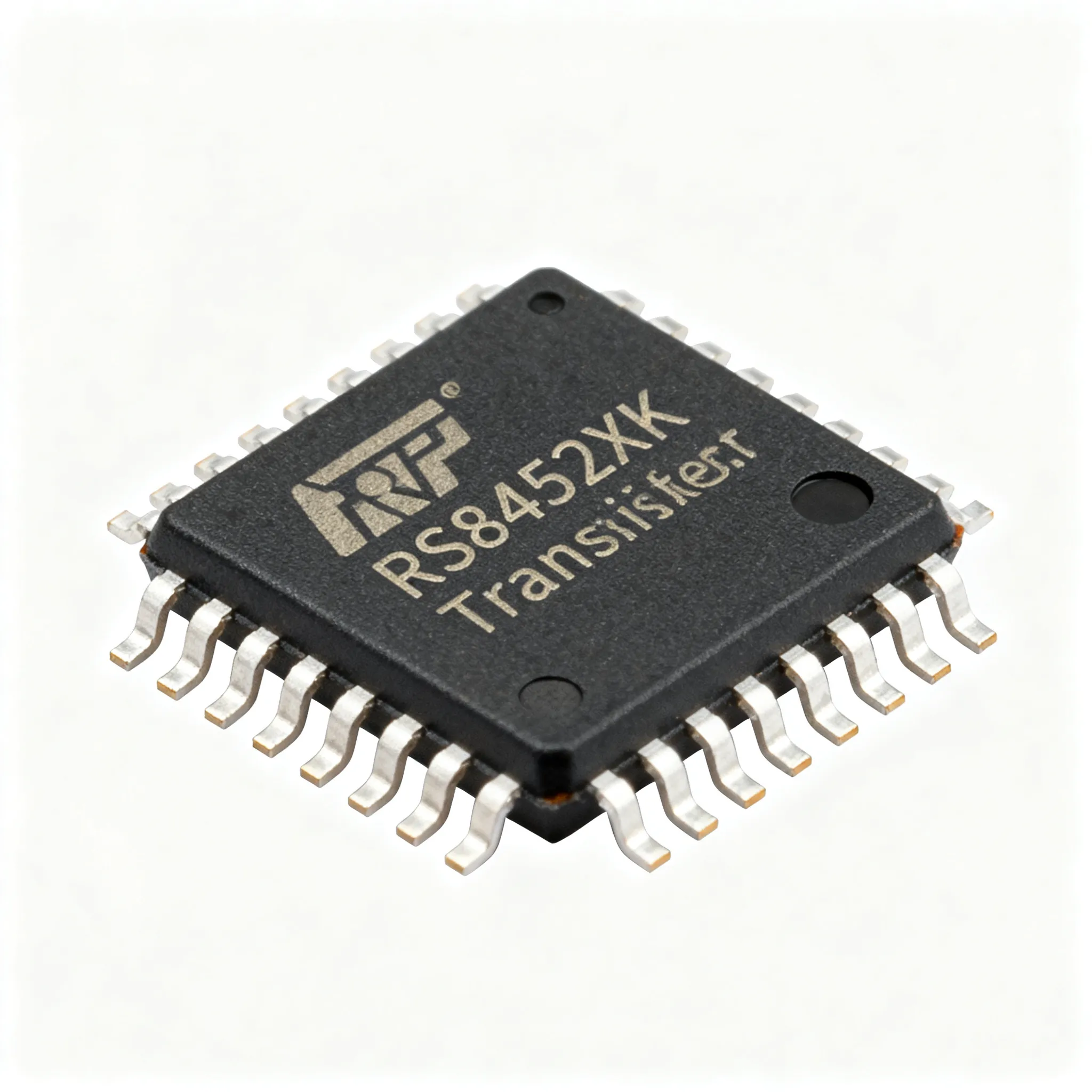
| Package options | SOIC‑8, MSOP‑8 | Industry‑standard footprints |
Tip: When migrating from a 5 V‑only transceiver to a 3.3 V system, verify that the differential output voltage still meets the minimum 1.5 V requirement at the lowest expected supply voltage and highest temperature. The RS8452XK’s output stage is designed to maintain margin even at 3.0 V, but a quick bench measurement with your specific cable load is always prudent.
RS8452XK vs. Alternatives: Sourcing, Performance, and Interface Trade‑offs
Choosing an RS‑485 transceiver often comes down to a three‑way tug‑of‑war among availability, ruggedness, and cost. The RS8452XK sits in a competitive field that includes the LTC1484 from Analog Devices, the SN65HVD75 from Texas Instruments, and various pin‑compatible devices from Maxim and Exar. To help you weigh the options, we’ve built a comparison matrix using real distributor data from Octopart and ICS‑Embedded, along with datasheet specifications⁴⁵. We also contrast RS‑485 with IrDA and RS‑232 interfaces to illustrate where differential signaling is non‑negotiable.
| Comparison Metric | RS8452XK (RUNIC) | LTC1484 (Analog Devices) | SN65HVD75 (TI) | Selection Criteria & Failure Boundary |
|---|---|---|---|---|
| Max data rate | 250 kbps | 250 kbps | 20 Mbps | 250 kbps covers most automotive/industrial buses; higher speed increases EMI and reduces cable length |
| Supply voltage range | 3.0 – 5.5 V | 3.0 – 5.5 V | 3.0 – 3.6 V | 5 V capability provides extra differential output margin for long, noisy buses |
| Receiver fail‑safe | Yes (internal bias) | Yes (internal bias) | Yes (internal bias) | All three prevent false UART triggers; verify threshold offset in datasheet |
| ESD (HBM, bus pins) | ±15 kV | ±15 kV | ±16 kV | ±15 kV is sufficient for unshielded cables; higher ratings add headroom for assembly handling |
| Common‑mode range | –7 to +12 V | –7 to +12 V | –7 to +12 V | All meet extended range; critical for ground‑bounce in vehicles |
| Package options | SOIC‑8, MSOP‑8 | SOIC‑8, MSOP‑8 | SOIC‑8, VSSOP‑8 | SOIC‑8 preferred for high‑vibration; MSOP saves board space in sensor nodes |
| Typical lead time (as of mid‑2025) | 4–6 weeks (stock available) | 8–12 weeks | 6–8 weeks | Steady stock at ICS‑Embedded and Octopart partners; single‑source risk from RUNIC⁵ |
| Unit price (1k qty) | $0.45–0.60 | $1.20–1.80 | $0.80–1.10 | Budget‑sensitive designs benefit from RUNIC’s aggressive pricing; second‑source the LTC1484 if supply continuity is critical |
For context, IrDA transceivers operate at data rates from 115.2 kbps to 16 Mbps but require line‑of‑sight and are limited to short distances⁶. RS‑232, while simple, uses single‑ended signaling with voltage levels between ±3 V and ±15 V, making it susceptible to ground noise and limiting cable length to about 15 m⁷. Neither can match RS‑485’s multi‑drop, long‑reach differential robustness. The RS8452XK’s combination of wide supply range, ±15 kV ESD, and internal fail‑safe makes it a drop‑in upgrade for legacy 5 V RS‑485 nodes that must now coexist with 3.3 V microcontrollers.
Where the RS8452XK Fits: From Under‑Hood Gateways to Factory‑Floor Sensor Buses
In a modern vehicle, the engine control unit (ECU) communicates with the transmission, ABS, and instrument cluster over CAN, but many sub‑systems still rely on RS‑485 for sensor aggregation and actuator control. The RS8452XK excels in these under‑hood gateways, where temperatures swing from –40 °C on a cold start to +125 °C near the exhaust manifold. Its SOIC‑8 package, with larger lead frame and gull‑wing leads, absorbs vibration and thermal expansion better than smaller leadless packages, reducing the risk of solder joint fatigue over the vehicle’s 15‑year life.
Industrial motor drives present a similar challenge. A variable‑frequency drive (VFD) enclosure is a cauldron of electromagnetic noise, with IGBT switching transients coupling onto communication cables. The RS8452XK’s controlled slew rate limits the harmonic content of the differential signal, while its wide common‑mode range prevents data corruption when the motor frame and control cabinet develop a potential difference of several volts. In a typical factory‑floor sensor bus, dozens of temperature, pressure, and flow sensors daisy‑chain over a single twisted pair, each node drawing minimal quiescent current. The transceiver’s 300 µA supply current and low‑power shutdown mode help keep the total bus power budget within the limits of a 4–20 mA loop or a small isolated DC‑DC converter.
Remote data acquisition units, such as those monitoring water treatment plants or oil pipelines, often sit in unheated enclosures where condensation and electrical overstress are constant threats. Here, the RS8452XK’s ±15 kV ESD rating on the bus pins provides a first line of defense against lightning‑induced transients, complementing external TVS diodes. The Infineon Power and Sensing Selection Guide highlights how robust interface ICs must integrate into a broader architecture of protected power supplies and galvanic isolation to achieve system‑level reliability⁸. The RS8452XK fits that philosophy: it handles the physical layer while you focus on the isolation barrier and power management.
Specifying the Right Data Rate, Supply Voltage, and Package for Your Worst‑Case Environment
Selecting the optimal configuration of the RS8452XK starts with a clear understanding of your bus topology and noise environment. Use the following decision flow to avoid the most common pitfalls.
- Determine the required data rate. For most industrial sensor networks, 115.2 kbps is plenty. If you’re streaming encoder data from a motor, 250 kbps may be necessary. Remember that cable length and data rate are inversely related: at 250 kbps, with proper 120 Ω termination and low‑capacitance twisted pair, you can reliably reach 300–400 m. If you need to go farther, drop the rate to 19.2 kbps and you can push beyond 1 km.
- Choose your supply voltage. If your microcontroller runs at 3.3 V, you can power the RS8452XK from the same rail, simplifying the BOM. However, a 5 V supply increases the differential output voltage, giving you an extra 300–500 mV of noise margin. In a factory with large VFDs, that margin can mean the difference between zero packet errors and a line shutdown. If you have a 5 V rail available, use it.
- Select the package based on mechanical stress. For modules mounted directly on the engine block or inside a transmission housing, the SOIC‑8 package’s larger solder joints are more resistant to thermal cycling and vibration. For space‑constrained sensor nodes inside a sealed enclosure, the MSOP‑8 package saves board area without sacrificing electrical performance. If your assembly process uses automated optical inspection (AOI), SOIC‑8’s exposed leads are easier to inspect than the hidden pads of a QFN.
- Verify fail‑safe behavior in your system. The RS8452XK’s internal biasing ensures the receiver output is high when the bus is idle. However, if you add external fail‑safe resistors to the A and B lines, make sure their combined impedance doesn’t overload the driver. A common mistake is using 560 Ω pull‑up/pull‑down resistors that consume 10 mA from the driver, reducing the differential voltage at the far end of the bus.
- Check distributor stock and plan for second‑source. As of mid‑2025, Octopart shows steady inventory of the RS8452XK through multiple partners, and ICS‑Embedded lists it with a 4–6 week lead time⁴⁵. Because it is a single‑source part from RUNIC, we recommend qualifying the pin‑compatible LTC1484 as a backup, especially for high‑volume automotive programs with 10‑year lifetime requirements. The datasheet archive on Datasheet Archive can help you compare footprint and timing differences⁹.
Below is a quick reference table that maps typical application profiles to the recommended RS8452XK configuration.
| Application Profile | Data Rate | Supply Voltage | Package | Key Reason |
|---|---|---|---|---|
| Under‑hood ECU gateway | 125 kbps | 5 V | SOIC‑8 | Max noise margin; vibration‑tolerant leads |
| Electric power steering sensor node | 250 kbps | 5 V | SOIC‑8 | High data rate for real‑time control; robust mechanical attachment |
| Factory‑floor temperature sensor bus | 19.2 kbps | 3.3 V | MSOP‑8 | Low power; small footprint for dense DIN‑rail modules |
| Remote pipeline monitoring RTU | 9.6 kbps | 3.3 V | SOIC‑8 | Long cable runs; wide temperature range; easy field replacement |
| HVAC damper actuator network | 115.2 kbps | 5 V | MSOP‑8 | Balanced speed and noise immunity; space‑constrained actuator housing |
Note: Always prototype with the actual cable type and length you’ll deploy. A 250 kbps signal that looks clean on a 1 m bench cable can collapse into a mess of reflections and intersymbol interference on a 300 m run with multiple stubs. Use a differential probe to verify eye diagrams at the farthest node before freezing the design.
RS8452XK Transceiver Questions Engineers and Buyers Ask Before Signing Off
Q: What is the maximum data rate of the RS8452XK and how far can I reliably run a bus at that speed?
A: The RS8452XK is typically specified to 250 kbps. At that rate, with proper termination and low‑capacitance twisted‑pair cable, reliable communication is achievable over several hundred metres. For longer runs, reducing the data rate to 19.2 kbps or adding RS‑485 repeaters is recommended. Always budget for at least 30% margin in your timing budget to account for temperature‑induced cable delay variations.
Q: Does the RS8452XK provide receiver fail‑safe when the bus is idle, open, or shorted?
A: Yes, the receiver incorporates internal biasing that forces a known logic state when the differential input is 0 V or floating, preventing false triggering of UARTs in noisy environments. This is a critical feature for multi‑drop buses where the master may tri‑state its driver between poll cycles.
Q: Which package options are available, and which one should I choose for high‑vibration automotive use?
A: The RS8452XK is offered in industry‑standard SOIC‑8 and smaller MSOP‑8 packages. For under‑hood or chassis‑mounted modules, the SOIC‑8 with its larger leads often proves more robust against vibration and thermal cycling. The MSOP‑8 is better suited for cabin‑mounted or sealed sensor nodes where space is at a premium.
Q: Can I power the RS8452XK from a 3.3 V rail, or is 5 V mandatory?
A: The device supports a wide supply range, typically 3.0 V to 5.5 V. Operating at 3.3 V reduces power consumption but slightly narrows the differential output voltage, so for long, noisy buses a 5 V supply gives extra margin. If your system already has a clean 5 V rail, use it to maximize noise immunity.
Q: What are the lead‑time and second‑source risks for the RS8452XK right now?
A: Current distributor listings on Octopart and ICS‑Embedded show steady stock, but it is a single‑source part from RUNIC Technology. Engineers should verify buffer stock and consider pin‑compatible alternatives like the LTC1484 if supply continuity is critical. For high‑volume production, negotiate a safety stock agreement with your distributor or qualify a second source during the design phase.
Q: How does the RS8452XK’s ESD protection compare with other RS‑485 transceivers used in automotive?
A: The device is rated to withstand ±15 kV HBM ESD on the bus pins, matching the protection level of the LTC1484 and meeting the robustness expected for unshielded cables in vehicle and industrial installations. This rating is tested per JEDEC JS‑001 and provides a solid first line of defense, though external TVS clamping is still recommended for systems exposed to severe transients.
References & Further Reading
- Ram Recalls 65,348 Trucks Over Instrument Cluster Failure – MoparInsiders
- Recall: Instrument Cluster Panel Display Failure (NHTSA 25V788) – Bronco Sport Forum
- LTC1484 Low Power RS485 Transceiver with Receiver Fail‑Safe – Analog Devices
- RS8452XK Distributor Availability and Datasheets – Octopart
- RS8452XK Stock and Quality Control – ICS‑Embedded
- Choosing the Right IrDA Transceiver: A Selection Guide – RF Wireless World
- Application Note RS‑232 Glossary and Selection Guide – Texas Instruments
- Infineon Power and Sensing Selection Guide 2021
- RS845 Datasheet Archive – Datasheet Archive
When your BOM calls for a rugged RS‑485 transceiver that won’t flinch at load dumps, ground shifts, or unshielded cables, the RS8452XK deserves a spot on your shortlist. For help balancing mixed BOMs or negotiating flexible MOQs, visit IC-Online—a resource built for engineers and procurement buyers who need reliable component data and supply