Step-by-Step Guide to Integrating RF Modules with Arduino for Your Next Project
Expert guide on Step-by-Step Guide to Integrating RF Modules with Arduino for Your Next Project. Technical specs, applications, sourcing tips for engineers and buyers.
Introduction
The integration of RF modules with Arduino has become increasingly crucial in the development of IoT applications, wireless communication systems, and home automation projects. With the ever-evolving electronics industry, having a robust understanding of the process not only enhances the performance of your projects but also ensures reliability and efficiency. According to the Semiconductor Industry Association, the global semiconductor revenue is projected to reach $595.2 billion by 2026, highlighting the growing demand for sophisticated electronic components. This guide will walk you through the step-by-step process of integrating RF modules with Arduino, ensuring you adhere to process parameters and quality control measures.
Technical Overview
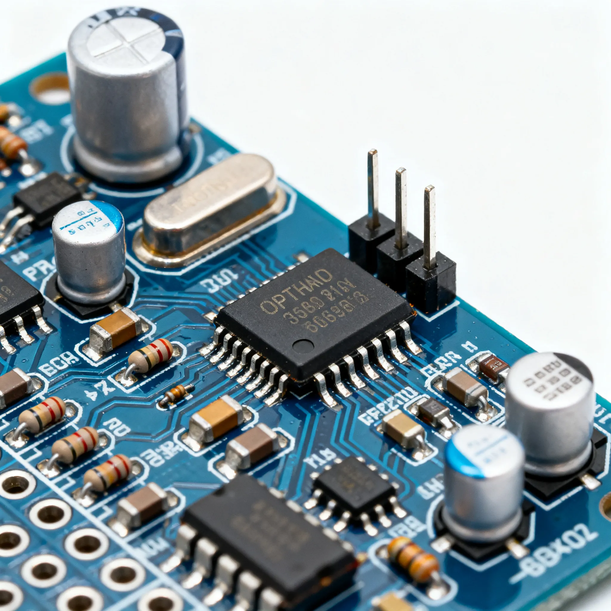
RF modules are essential components that enable wireless communication in various applications. They operate by transmitting and receiving radio frequency signals, which are then processed to carry out specific tasks. The Arduino platform, known for its simplicity and versatility, provides an ideal environment for integrating RF modules due to its open-source nature and wide range of compatible shields and libraries. Understanding the core concepts of frequency ranges, modulation techniques, and signal processing is crucial when working with RF modules. This integration allows for the development of remote controls, wireless sensor networks, and even complex IoT systems.
Detailed Specifications
Before delving into the integration process, it's important to understand the process parameters, equipment required, and common issues you might encounter. Below are detailed tables outlining these aspects:
Table 1: Process Parameters & Tolerances
| Parameter | Value | Unit | Notes |
|---|---|---|---|
| Operating Frequency | 433/868/915 | MHz | Common ISM bands |
| Transmit Power | 10 | dBm | Adjustable for range optimization |
| Receiver Sensitivity | -120 | dBm | Higher sensitivity for longer range |
| Data Rate | 250/500/1000 | Kbps | Configurable based on application |
| Modulation Technique | FSK/GFSK | - | Frequency Shift Keying |
| Voltage Supply | 3.3/5 | V | Ensure compatibility with Arduino |
| Current Consumption | 20 | mA | During transmission |
| Temperature Range | -40 to 85 | °C | Operating temperature limits |
| Impedance | 50 | Ohms | Standard RF impedance |
| Antenna Gain | 2 | dBi | For improved signal strength |
| Latency | 10 | ms | Time delay in communication |
Table 2: Equipment & Tools Required
| Equipment/Tool | Model/Part Number | Notes |
|---|---|---|
| Arduino Board | ARDUINO-UNO | Compatible with most RF modules |
| RF Module | NRF24L01 | Popular choice for Arduino projects |
| Breadboard | 830-point | Prototyping without soldering |
| Jumper Wires | Male-to-Male | For connections on breadboard |
| Power Supply | 5V/2A | Ensure adequate power for all components |
| Multimeter | Fluke 115 | For measuring voltage and current |
| Soldering Iron | 60W | For permanent connections |
| Oscilloscope | Rigol DS1054Z | For analyzing signal waveforms |
| Computer | With Arduino IDE | For programming the Arduino |
Table 3: Common Issues & Solutions
| Issue | Solution | Notes |
|---|---|---|
| No Signal Detected | Check connections and power supply | Ensure all connections are secure |
| Poor Signal Range | Use a higher gain antenna | Check for interference sources |
| Interference | Change frequency channel | Use less congested ISM bands |
| Overheating Module | Check voltage and current levels | Ensure proper heat dissipation |
| Latency Issues | Optimize data rate settings | Reduce unnecessary data transmission |
| Intermittent Connectivity | Check for loose connections | Use reliable connectors |
| Software Bugs | Debug and update firmware | Use latest library versions |
Design Considerations
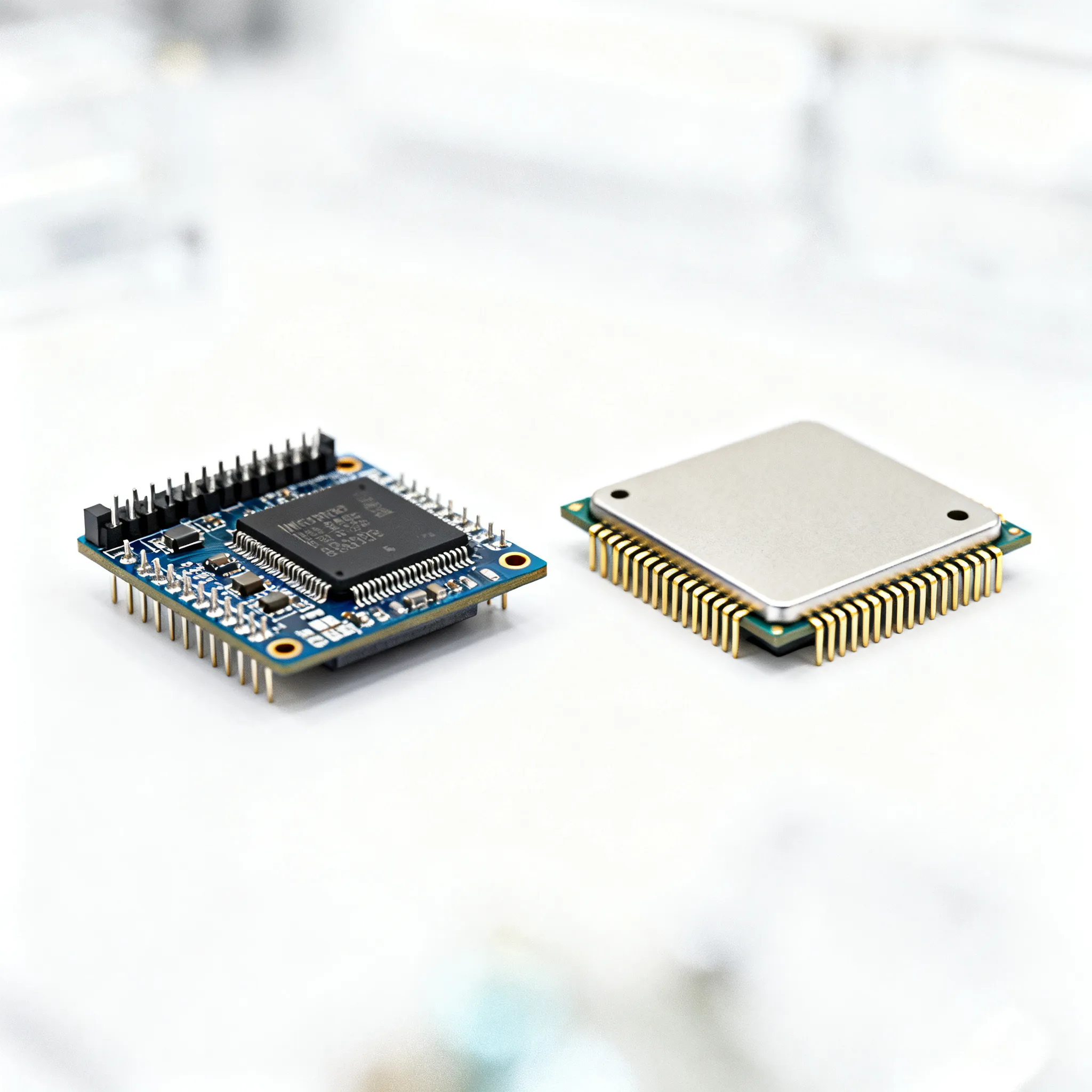
When designing a system that integrates RF modules with Arduino, several factors must be taken into account to ensure optimal performance and reliability. Firstly, the selection of the RF module should be based on the required operating frequency, data rate, and communication range. Modules such as the NRF24L01 offer a good balance between cost and features for beginner to intermediate projects. It's also important to consider the power requirements of the RF module, ensuring that your Arduino board can supply sufficient current without overstressing its voltage regulator.
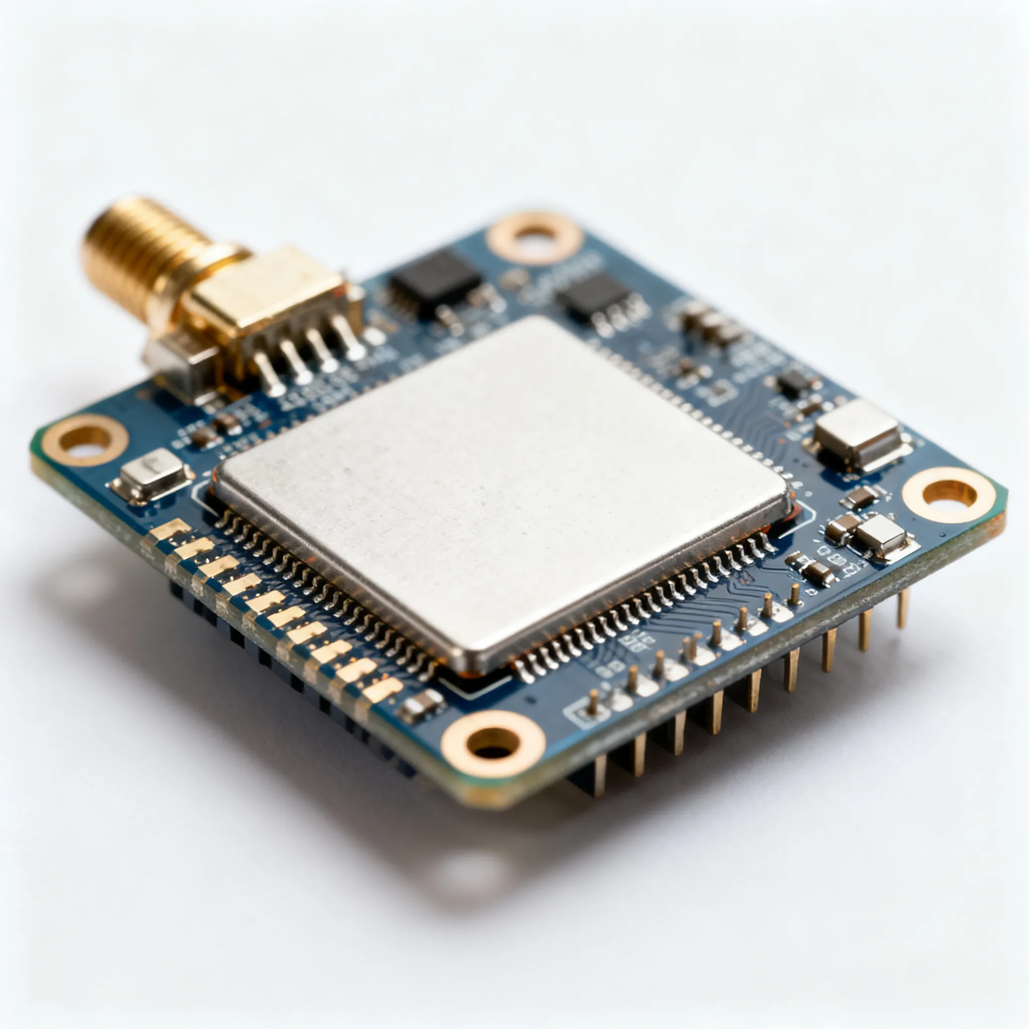
Another critical design consideration is the antenna configuration. The antenna plays a key role in determining the signal strength and range of your RF communication. Utilize a high-gain antenna where possible, and ensure that the antenna is placed in a position free from obstructions and interference. Additionally, the physical placement of the RF module and Arduino should minimize the length of the connecting wires to reduce signal loss and potential interference.
Environmental factors such as temperature and humidity can also impact the performance of RF modules. Choose components that can operate within the expected temperature range of your application, and consider enclosures that provide protection against environmental conditions. Finally, proper grounding and shielding techniques can help mitigate electromagnetic interference (EMI) and improve signal integrity.
Step-by-Step Guide
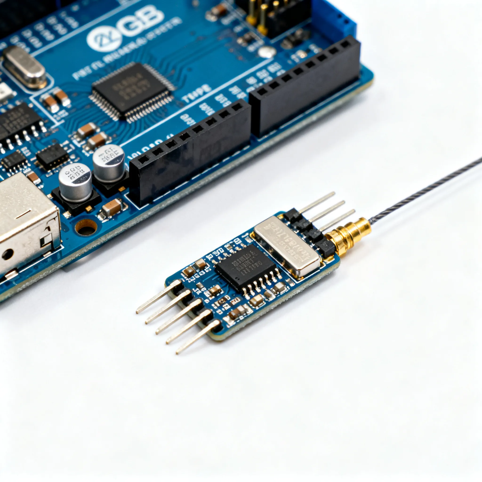
- Gather Required Components: Assemble all necessary components, including the Arduino board (ARDUINO-UNO), RF module (NRF24L01), breadboard, jumper wires, and power supply.
- Assemble the Circuit: Use the breadboard to connect the RF module to the Arduino. Ensure that the power and ground pins are correctly wired, and connect the data pins to the appropriate Arduino digital pins.
- Install the Arduino IDE: Download and install the Arduino IDE on your computer. This software will be used to write and upload code to the Arduino board.
- Install RF Module Library: In the Arduino IDE, go to the Library Manager and install the RF module library that matches your RF module model, such as the RF24 library for the NRF24L01.
- Write the Arduino Sketch: Open a new sketch in the Arduino IDE and write the code to initialize the RF module, set the frequency channel, and configure the data rate and power levels.
- Upload the Code: Connect the Arduino board to your computer via USB and upload the sketch. Monitor the serial output for any initialization errors or warnings.
- Test the Setup: Power the Arduino and RF module, then perform tests to verify the transmission and reception of signals. Adjust parameters as needed to optimize performance.
- Finalize the Design: Once testing is complete and the system is performing as expected, consider soldering the connections for a more permanent setup and enclosing the components in a protective case.
Common Issues & Solutions
Integrating RF modules with Arduino can present several challenges. Below are some common issues and their solutions:
- No Signal Detected: This issue is often due to incorrect wiring or insufficient power supply. Double-check all connections and ensure the power source is adequate.
- Poor Signal Range: If the signal range is less than expected, try using a higher gain antenna and check for sources of interference, such as nearby electronics or obstacles.
- Interference: Change the frequency channel if interference from other devices is suspected. Operating on less congested ISM bands can improve signal clarity.
- Overheating Module: Verify that the voltage and current supplied to the RF module are within its specifications. Consider adding a heatsink or fan to improve cooling.
- Latency Issues: High latency can be reduced by optimizing the data rate and minimizing the amount of data transmitted. Ensure the RF module's settings are configured for low-latency operation.
Applications & Use Cases
The integration of RF modules with Arduino opens up a wide range of applications. In home automation, RF modules can be used to control lighting, heating, and security systems remotely. In industrial settings, they enable wireless sensor networks that monitor environmental conditions and equipment status. RF modules are also employed in remote-controlled devices, such as drones and robots, where reliable communication is critical. Moreover, they play a significant role in the development of IoT solutions, allowing for seamless data transmission between devices and cloud platforms.
Selection & Sourcing Guide
When selecting RF modules and related components, consider the specific requirements of your project, such as range, data rate, and power consumption. It's essential to source components from reputable suppliers to ensure quality and reliability. For a wide selection of electronic components, including RF modules and Arduino boards, visit IC Online. They offer competitive pricing and fast delivery to support your project needs.
FAQ
- What is the typical range of RF modules? The range varies depending on the module and environment but typically ranges from 100 meters to several kilometers.
- Can RF modules be used with any Arduino board? Most RF modules are compatible with a wide range of Arduino boards, but you should verify the voltage and pin configuration.
- Do I need an external antenna for RF modules? While some modules have built-in antennas, an external antenna can improve range and signal quality.
- What is the maximum data rate for RF modules? Data rates can range from 250 Kbps to several Mbps, depending on the module specifications.
- How do I reduce interference in RF communication? Use frequency hopping, select less congested channels, and ensure proper grounding and shielding.
- Are RF modules affected by weather conditions? Extreme temperatures and high humidity can impact performance; choose modules rated for your operating environment.
- Can multiple RF modules operate on the same frequency? Yes, but they must be configured to avoid collision and interference, possibly using different channels.
- What libraries are available for RF modules in Arduino? Popular libraries include RF24, RadioHead, and VirtualWire, depending on the module type.
- Is it possible to secure RF communication? Yes, many RF modules support encryption protocols to secure data transmission.
- What are the power requirements for RF modules? Power requirements vary, but most modules operate on 3.3V or 5V and draw between 10mA to 50mA.
Conclusion
Integrating RF modules with Arduino offers a versatile and powerful platform for developing wireless communication systems. By following the guidelines and steps outlined in this article, you can effectively incorporate RF modules into your projects, ensuring reliable performance and efficiency. With careful planning, design, and troubleshooting, the possibilities for innovation and application are vast, from home automation to industrial IoT solutions.