The 2025 ADSP-21569 EZKIT Manual A Quick Guide
This guide accelerates development with the ADSP-21569 EZ-KIT. It offers a shortcut to understanding the powerful SHARC+ eva
This guide accelerates development with the ADSP-21569 EZ-KIT. It offers a shortcut to understanding the powerful SHARC+ evaluation board. The embedded digital signal processor (DSP) market is projected to maintain a Compound Annual Growth Rate (CAGR) of 12% from 2025 to 2033. Developers can master the official analog devices adsp-21569 ezkit manual by focusing on four core areas:
- Hardware Setup
- Software Tools
- Code Examples
- Debugging
This approach avoids reading the entire technical document. It provides a direct path to using the processor effectively.
Key Takeaways
- Set up the ADSP-21569 EZ-KIT board correctly. Connect power and USB in the right order. Check switches and jumpers for proper board behavior.
- Install CrossCore Embedded Studio (CCES) software. This tool helps you write and test code for the processor. Make sure to select SHARC+ processor support during installation.
- Use the example projects provided by Analog Devices. These examples show how the processor works. They help you quickly learn and test the board's features.
- Learn to debug your code. Use CCES to find and fix problems. Set breakpoints to pause your program and check what is happening inside the processor.
Navigating the Analog Devices ADSP-21569 EZKIT Manual
Developers begin their journey by understanding the physical evaluation board. The analog devices adsp-21569 ezkit manual contains detailed diagrams. These visuals are essential for locating key hardware features. A solid grasp of the board's layout is the first step toward successful project development.
Board Layout and Key Components
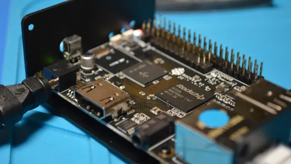
The EZ-KIT board is a dense platform centered around the ADSP-21569 processor. This processor sits in a 400-ball BGA package. Developers should first locate the primary connectors. These include USB for debugging, audio I/O jacks, and expansion headers. On-board LEDs provide visual feedback for power status and user-defined functions.
The analog devices adsp-21569 ezkit manual also details important switches and jumpers. These components configure the board's behavior. Understanding their functions is critical for setup.
| Component | Function |
|---|---|
| Boot Mode Switches | Determine how the processor starts. Options include SPI Master Boot (default), SPI Slave Boot, and UART Boot. |
| JTAG Interface Switches (SW5) | Configure the board for a single processor setup or a multiprocessor configuration for advanced debugging. |
| HADC Jumper | Connects the processor's Housekeeping ADC to on-board voltages for system monitoring. |
Powering and Connecting the Board
Properly powering the board is a simple but crucial process. The board uses a single 5V DC power supply connected via a barrel jack.
Note: Always connect the USB cable between the PC and the board's debug agent port before applying power. This ensures the debug agent initializes correctly.
The manual outlines the steps to achieve the processor's maximum performance. The on-board 25 MHz oscillator provides the base clock. An internal phase-locked loop (PLL) multiplies this frequency. This allows the SHARC+ core to reach its impressive 1 GHz clock speed. Following the power-up sequence in the analog devices adsp-21569 ezkit manual ensures the processor operates at its full potential right from the start. This prepares the hardware for software development and debugging tasks.
Software Development with CCES
Hardware setup is only the first half of the equation. Effective software development brings the ADSP-21569 processor to life. Analog Devices provides CrossCore® Embedded Studio (CCES), the recommended Integrated Development Environment (IDE). This powerful software suite contains all the necessary tools. Developers use it to write, compile, and debug applications specifically for the SHARC+ architecture.
CCES Installation and Setup
The analog devices adsp-21569 ezkit manual provides detailed instructions for installing CCES. The process is straightforward and guided by an installation wizard. Developers should follow these general steps:
- Download: Obtain the latest version of CCES from the Analog Devices website.
- Install: Run the installer and follow the on-screen prompts. The installer includes the IDE, compiler, and necessary drivers.
- Activate: Activate the software with either a full license or a free evaluation license upon first launch.
Pro Tip: 💡 During installation, ensure the option to install support for "ADSP-SC5xx/ADSP-215xx (SHARC+) Processors" is selected. This guarantees that all drivers and board support packages for the EZ-KIT are installed correctly.
Proper installation is the foundation for a smooth development workflow.
Creating Your First Project
With CCES installed, developers can create their first project. The IDE includes a project creation wizard that simplifies this task. The wizard configures the project to target the specific processor and its architecture.
When using the wizard, it is critical to select the ADSP-21569 processor. This action tells CCES to use the correct compiler settings and libraries for the SHARC+ core. This core is renowned for its high-performance 32/40/64-bit floating-point capabilities, making it ideal for complex audio and signal processing algorithms. The wizard generates a basic project structure, including a main source file. This file is the entry point for the developer's custom code.
/* A basic starting point in main.c */
#include <sys/platform.h>
#include "adi_initialize.h"

int main(int argc, char *argv[])
{
	/**
	 * Initialize managed drivers and applications components.
	 */
	adi_initComponents();

	/* Begin adding your custom code here */

	return 0;
}
This simple framework allows developers to immediately begin programming the processor.
Practical Code Examples and Applications
Theoretical knowledge becomes practical skill when developers compile and run code. The ADSP-21569 EZ-KIT manual points to a rich library of code examples. These examples are the fastest way to verify the hardware setup and begin exploring the processor's capabilities. They provide a solid foundation for building custom applications.
Using Included Example Projects
Analog Devices provides a comprehensive Board Support Package (BSP) for the EZ-KIT. This package is a crucial resource containing drivers, libraries, and numerous example projects. Developers can download the complete package directly from the Analog Devices website.
- ADSP-2156x EZ-KIT® Board Support Package: Available from the official Analog Devices software examples portal.
These projects demonstrate specific functionalities of the processor. They cover a wide range of applications from basic audio passthrough to advanced signal processing.
| Example Project | Description |
|---|---|
| Audio Loopback TDM | Passes audio from the ADC to the DAC using Time-Division Multiplexing mode. |
| FIR Multi Channel Processing | Demonstrates the powerful on-chip FIR accelerator for filter applications. |
| Device Programmer | Implements the interface for programming the on-board flash memory. |
Importing these examples into CCES is a simple process:
- Download and unzip the BSP to a local directory.
- Open CCES and navigate to
File > Import. - Select
General > Existing Projects into Workspaceand clickNext. - Browse to the directory where the example projects are located.
- Select the desired project from the list and click
Finish.
The project will now appear in the Project Explorer, ready to be built and debugged.
Running a Basic Demo
Running a pre-built demo is an excellent first step. The Audio Loopback TDM example is a perfect choice. After importing and building the project, developers can run it on the hardware. This test confirms that the audio codecs, serial ports, and core processor are functioning correctly. A successful run involves playing audio into the board's input jack and hearing it on the output.
More advanced examples showcase the processor's true power. The FIR Multi Channel Processing demo highlights the dedicated filter accelerator. Recent library optimizations for the SHARC+ core have significantly increased efficiency. Benchmarks show that designs using FIR filters can gain more than 13% processing headroom, freeing the core for other tasks. Running these demos gives developers direct insight into the performance they can expect for demanding DSP applications.
Debugging and Programming the Processor
A robust debugging process is essential for efficient development. It allows developers to find and fix issues within their code. CrossCore® Embedded Studio (CCES) integrates powerful debugging tools. These tools work directly with the EZ-KIT hardware. This enables a seamless workflow from writing code to testing it on the processor. Mastering these tools saves significant time and effort.
Using the On-Board Debug Agent
The EZ-KIT includes an on-board debug agent. This agent acts as the bridge between the developer's PC and the ADSP-21569 processor. CCES communicates through this agent to control code execution and inspect the system. To start a debug session, developers create a launch configuration in the IDE. This configuration tells CCES how to connect to the target board.
Occasionally, CCES may fail to connect. The manual provides troubleshooting steps for these situations. Developers should investigate the following common issues:
- Check Jumper Settings: Verify the configuration of jumpers like JP1-JP5. Incorrect settings can prevent a connection.
- Power Cycle the Board: Unplug and replug the power cable after flashing a new program. This resets the board and loads the new image.
- Try Different RS232 Hardware: Some serial adapters cause issues. An adapter with a reliable FTDI chipset is a good alternative.
- Verify Port Settings: Ensure the computer's COM port settings match the required configuration.
- Check for COM Port Interference: Other software can sometimes block the COM port.
- Inspect Physical Connection: Examine the board's connectors for any physical damage.
Setting Breakpoints and Inspecting Memory
Once connected, developers can use core debugging features. Setting a breakpoint is a fundamental technique. A breakpoint pauses program execution at a specific line of code. In CCES, developers set a breakpoint by clicking in the margin next to a line number.
When the processor hits a breakpoint, the developer can inspect the complete state of the system. This is the most powerful part of the debugging process.
Debugging in Action 🔍: A common task is to inspect an audio buffer in memory. A developer can set a breakpoint after the buffer is filled. They can then open a memory view in CCES to see the raw sample data. This helps verify that the ADC is working and that the data format is correct before it gets processed further.
This capability allows developers to step through code line-by-line, watch variable values change, and pinpoint the exact source of any bugs.
This guide provides a direct path through the analog devices adsp-21569 ezkit manual. Developers can accelerate their projects by focusing on four key areas:
- Hardware familiarization
- CCES software setup
- Practical code examples
- Debugging techniques
Mastering these sections of the analog devices adsp-21569 ezkit manual is the fastest way to leverage the processor's powerful features. This includes its large 5 Mb on-chip L1 SRAM. Developers can now confidently start their next audio effects processor or multi-channel audio system.
FAQ
What is the main advantage of the SHARC+ core?
The SHARC+ core excels at high-performance floating-point math. It processes 32-bit, 40-bit, and 64-bit data types. This capability makes it ideal for demanding audio and industrial signal processing applications that require high precision.
Where can developers find the Board Support Package (BSP)?
Developers download the Board Support Package from the Analog Devices website. The BSP contains essential drivers, libraries, and example projects. It is a critical resource for starting development with the ADSP-21569 EZ-KIT.
Can this board be used for multi-processor systems?
Yes, the EZ-KIT supports multi-processor configurations. Developers can configure the JTAG interface switches (SW5) to link multiple boards. This setup enables the development and debugging of complex, high-performance systems using several SHARC+ processors.
What if CCES cannot connect to the board?
First, check the board's jumper settings and USB connection. A power cycle often resolves temporary issues. Ensure no other software is using the COM port. Verifying these simple hardware steps can save significant debugging time.
Where can developers find expert design solutions?
Developers seeking advanced solutions can engage with official Analog Devices partners. These specialized design houses offer expert services for complex projects. They help accelerate product development and solve difficult engineering challenges for the SHARC+ architecture.