

Case Study: Calibrating Sensor Front-Ends with the Bourns 3313J-1-503E SMD Trimmer
Expert guide on Case Study: Calibrating Sensor Front-Ends with the Bourns 3313J-1-503E SMD Trimmer. Technical specs, applications, sourcing tips for engineers and buyers.
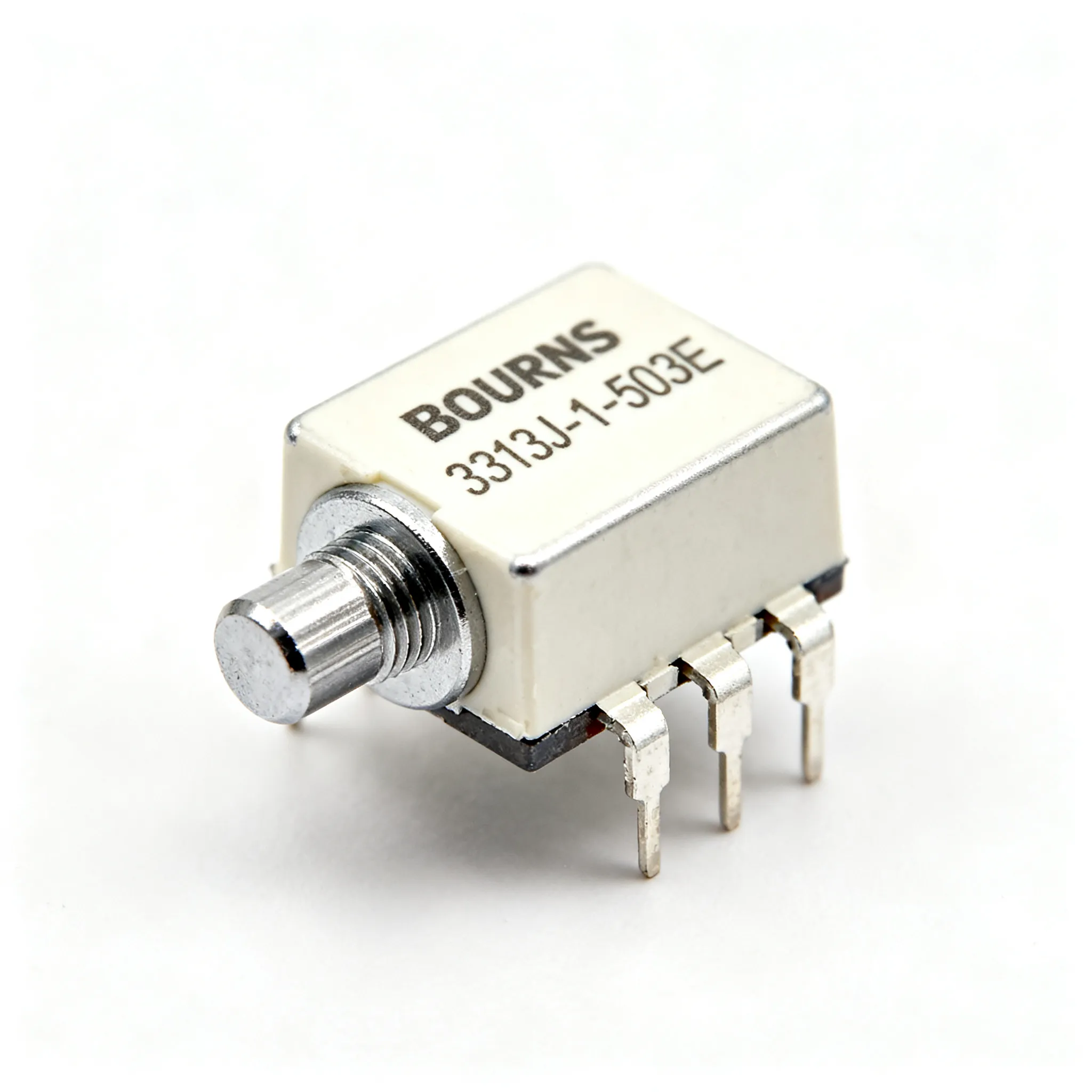
Case Study: Calibrating Sensor Front-Ends with the Bourns 3313J‑1‑503E SMD Trimmer
When your pressure transducer’s zero offset drifts beyond the correction range of the instrumentation amplifier, or a strain‑gauge bridge imbalance refuses to settle within the ADC’s input span, the solution often isn’t another line of firmware—it’s a physical trim. The Bourns 3313J-1-503E 3 mm SMD trimmer potentiometer has quietly held its place on precision sensor boards for years, and with good reason. This case study walks through how the device is used to calibrate sensor front‑ends, what makes its 50 kΩ cermet element a dependable choice, and how to source it without surprises.
Why Sensor Front‑End Calibration Still Demands a Tiny Trimmer in the Age of Digital Compensation
Modern sensor signal chains lean heavily on auto‑zero amplifiers, 24‑bit delta‑sigma ADCs, and polynomial linearisation in the microcontroller. Yet even the most sophisticated digital compensation can’t fix every analog imperfection. A Wheatstone bridge excited by a ratiometric voltage still exhibits initial imbalance from manufacturing tolerances, long‑term drift of the sensing element, and offset voltages that vary over temperature. Software can subtract a static offset, but if the front‑end saturates or the common‑mode voltage wanders outside the amplifier’s input range, no amount of code will recover the signal.
That’s where a physical trimmer like the 3313J-1-503E proves its worth. By placing a 50 kΩ adjustable resistor in series with one leg of a bridge or in the feedback network of an op‑amp, you can null the offset at the source, keeping the entire signal chain within its linear window. The trimmer’s single‑turn, top‑adjust design lets production technicians or automated optical alignment systems dial in the correct value quickly, while the cermet element holds that setting through temperature swings from –55 °C to +125 °C.
From a procurement standpoint, the 3313J-1-503E has remained accessible even as lead times for many passives stretched. Recent snapshots from major distributors show healthy stock levels. Mouser lists the part with real‑time inventory and datasheet access, while DigiKey shows same‑day shipping availability. Arrow carries the device with AEC‑Q200 qualification noted, though larger volumes may require a quote. Still, multi‑sourcing vigilance remains essential—no single distributor can guarantee zero lead‑time variability, and the trimmer’s compact J‑hook footprint means a second source isn’t always a drop‑in replacement.
Inside the 3313J‑1‑503E: Cermet, Single‑Turn, and What 50 kΩ Means for Your Sensor Bridge
At its core, the 3313J-1-503E is a cermet (ceramic‑metal) thick‑film potentiometer. Cermet elements offer a compelling mix of low temperature coefficient (±100 ppm/°C typical), good stability under humidity, and a hard surface that withstands repeated wiper cycles better than conductive plastic in dry environments. The 50 kΩ end‑to‑end resistance is a deliberate choice for high‑impedance sensor dividers: it keeps bridge current low enough to avoid self‑heating errors while presenting a manageable source impedance to the following amplifier. With a 20 % tolerance on absolute resistance, the trimmer is not meant to set a precise fixed value; its role is ratiometric adjustment, where the wiper position defines a fraction of the total resistance.
The single‑turn mechanical design provides roughly 240° of electrical travel. That’s a practical compromise—enough resolution to null typical sensor offsets without the tedious multi‑turn tweaking that slows production. The J‑hook surface‑mount termination (often called gull‑wing) is reflow‑compatible and provides a reliable solder joint that can be visually inspected. The device’s 0.125 W power rating at 70 °C may seem modest, but in a sensor front‑end where the trimmer passes only microamperes, it’s more than adequate.
The following table summarises the key parameters that matter when integrating the 3313J-1-503E into a sensor calibration circuit.
| Parameter | Value/Range | Unit/Notes |
|---|---|---|
| Resistance (end‑to‑end) | 50 | kΩ, ±20 % tolerance |
| Element material | Cermet | Thick‑film on ceramic substrate |
| Power rating | 0.125 (1/8) | W at 70 °C, derate to 0 at 125 °C |
| Number of turns | 1 (electrical), 1 (mechanical) | Approx. 240° electrical travel |
| Adjustment orientation | Top (vertical) | J‑hook SMD termination |
| Temperature range | –55 to +125 | °C, operating |
| Temperature coefficient | ±100 | ppm/°C typical |
| Contact resistance variation | ≤2 % or 3 Ω (whichever greater) | After proper setting |
| Mechanical endurance | 100 | Cycles, typical |
| Sealing | Not sealed (open frame) | Conformal coating recommended for harsh environments |
| Qualification | AEC‑Q200 | Per Arrow product page |
The 50 kΩ value is particularly well‑suited to sensor bridges with arm resistances in the 1 kΩ to 10 kΩ range. When placed as a variable resistor in series with one arm, the trimmer can shift the bridge balance by several percent without introducing excessive noise. The 20 % tolerance on absolute resistance means the trim range must be calculated for worst‑case initial values. For example, a 50 kΩ trimmer could actually measure 40 kΩ or 60 kΩ; if your circuit relies on a specific end‑to‑end resistance for the divider ratio, you’ll need to verify the adjustment range covers all corners. In practice, the ratiometric nature of the trimmer makes this manageable—the wiper position alone determines the output, and the absolute value primarily affects the impedance seen by the wiper node.
The Bourns 3313 series datasheet, available through Alldatasheet, provides detailed footprint dimensions and soldering profiles. The J‑hook leads require a pad layout that accounts for the 3.2 mm × 3.5 mm body, and the top‑adjust screwdriver slot demands clearance above the board. For designs where vertical access is impractical, the horizontal‑adjust variant 3313J‑2‑503E offers an identical electrical specification with a side‑facing adjustment slot.
Where the 3313J‑1‑503E Shines: Real Sensor Front‑End Calibration Scenarios
The Bourns 3313J-1-503E appears in a surprisingly wide range of sensor calibration topologies, many of which are detailed in Bourns’ own Sensors and Controls Solutions Guide. The following scenarios represent the most common applications we encounter in industrial, medical, and automotive sensor modules.
Pressure Transducer Zero‑Offset Nulling. A typical piezoresistive pressure sensor delivers a differential millivolt signal riding on a common‑mode voltage near half the excitation. Manufacturing tolerances create an initial offset that can be as large as ±30 mV/V. By inserting the 3313J-1-503E as a variable resistor between the bridge’s negative output and ground (or in a dedicated offset‑null pin of an instrumentation amplifier), the production line can zero the output at the reference pressure. The trimmer’s 50 kΩ value keeps the loading on the bridge negligible, and the cermet element’s low TC ensures the null setting holds over the –40 °C to +85 °C operating range typical of industrial transmitters.
Strain‑Gauge Bridge Balancing. Load cells and torque sensors often use four‑element Wheatstone bridges with nominal 350 Ω or 1 kΩ arms. Small mismatches in gauge resistance or bonding stress create an offset that can saturate a high‑gain amplifier. A trimmer placed in a parallel “balance” network—often a resistor and trimmer in series across one arm—allows fine adjustment without disturbing the bridge’s temperature compensation. The single‑turn design of the 3313J-1-503E gives enough resolution to trim offsets down to microvolts per volt, provided the wiper is buffered by a high‑impedance op‑amp.
Thermistor Linearisation. NTC thermistors exhibit a highly non‑linear resistance‑temperature curve. A common linearisation technique places a fixed resistor in parallel with the thermistor and a trimmer in series to fine‑tune the inflection point. The 50 kΩ trimmer is ideal for 10 kΩ or 100 kΩ thermistors, allowing the circuit to be adjusted for best linearity over a specific temperature window. Because the trimmer carries only the small excitation current, self‑heating is minimal.
Photodiode Transimpedance Gain Setting. In a transimpedance amplifier (TIA), the feedback resistor sets the gain. When the photodiode’s responsivity varies from lot to lot, a fixed resistor forces the designer to either accept gain error or select‑on‑test resistors. Replacing the feedback resistor with the 3313J-1-503E in series with a fixed resistor creates an adjustable gain stage. The trimmer’s wiper resistance (typically a few ohms) adds negligible noise in the TIA’s feedback path, and the cermet element’s low current noise keeps the signal‑to‑noise ratio high.
These applications all share a common requirement: a compact, reflow‑compatible adjustment that survives harsh environments without the bulk of a through‑hole potentiometer. Yet the trimmer isn’t the only calibration method available. The table below compares the 3313J-1-503E against alternative approaches often considered for sensor front‑ends.
| Calibration Method | Typical Resolution | Temperature Stability | Production Complexity | Best Suited For |
|---|---|---|---|---|
| Bourns 3313J-1-503E SMD Trimmer | ~0.5 % of full scale (single‑turn) | ±100 ppm/°C (cermet), stable after setting | Low—manual or automated screwdriver adjustment | One‑time factory calibration, harsh environments, AEC‑Q200 requirements |
| Digital Potentiometer (e.g., 256‑tap) | 0.4 % per step | ±35 ppm/°C typical, but wiper resistance drift can be higher | Medium—requires I²C/SPI communication and non‑volatile memory | In‑situ recalibration, remote adjustment, applications needing digital control |
| Fixed Resistor Selection (binning) | Discrete steps (E96 series) | ±25 ppm/°C or better with thin‑film | High—requires measurement and manual or automated pick‑and‑place of specific values | High‑volume production where trimmer cost is unacceptable, but only if offset distribution is narrow |
| Laser‑Trimmed Thick‑Film Network | 0.1 % or better | ±50 ppm/°C tracking | Very high—requires laser trim equipment and real‑time measurement | Ultra‑high precision, fully automated lines, cost‑insensitive applications |
For most mid‑volume sensor products, the 3313J-1-503E hits the sweet spot. It avoids the software overhead and potential reliability concerns of a digital pot, while offering far more flexibility than fixed resistor binning. The laser‑trimmed network is overkill unless you need 0.1 % absolute accuracy and can amortise the capital equipment cost. The trimmer’s single‑turn resolution is sufficient when the adjustment range is a few percent of the sensor span, and its mechanical stability means the setting won’t wander after vibration or thermal cycling—provided the wiper is not subjected to continuous current.
Sourcing and Design Tips: Avoiding Drift, Noise, and Stock‑Outs with the 3313J‑1‑503E
Integrating the 3313J-1-503E successfully requires attention to both electrical and mechanical details, as well as a procurement strategy that keeps the production line running.
Design Guidelines. The most common pitfall is excessive wiper current. Bourns specifies a minimum wiper current of 10 µA to maintain a clean contact; below that, contact resistance can become erratic over time. Conversely, continuous wiper currents above 1 mA accelerate wear on the cermet track. In a sensor front‑end, the wiper should always feed a high‑impedance node—an op‑amp input or an ADC buffer—so that the current through the wiper is essentially zero after the initial adjustment. If the trimmer is used as a variable resistor (two‑terminal connection), tie the unused terminal to the wiper to prevent open‑circuit conditions during adjustment.
Placement on the PCB matters. Keep the trimmer away from switching nodes (DC‑DC converters, high‑speed digital lines) to avoid capacitive coupling of noise into the high‑impedance wiper node. A guard ring connected to a low‑impedance reference can help in extreme cases. Also, remember that the 3313J-1-503E is an open‑frame device. In condensing humidity or dusty environments, apply a conformal coating after calibration—but test that the coating doesn’t wick into the adjustment slot and freeze the rotor. The mechanical end‑stops are rated for 100 cycles, so plan for a single factory calibration; field re‑adjustment is not recommended.
Procurement Strategy. While the 3313J-1-503E is widely available, lead times can stretch during periods of high demand for automotive‑grade passives. The table below summarises the distribution landscape based on recent checks.
| Distributor | Part Number | Stock Status (Typical) | Lead Time (Volume Orders) | Notes |
|---|---|---|---|---|
| Mouser | 3313J-1-503E | In stock | 6–8 weeks | Real‑time inventory, datasheet downloads |
| DigiKey | 3313J-1-503E | In stock, ships same day | 8 weeks typical | Competitive pricing on reels |
| Arrow | 3313J-1-503E | Available, quote required for volume | Quote‑based | AEC‑Q200 noted, good for automotive programs |
| TME | 3313J-1-503E | Available | Check at order | European warehouse, alternative for EMEA buyers |
| Ariat‑Tech | 3313J‑2‑503E (horizontal adjust) | New and original in stock | DHL/FedEx/UPS shipping | Drop‑in alternative if vertical adjustment not required; verify authenticity |
The 3313J‑2‑503E horizontal‑adjust variant, available from Ariat‑Tech, shares the same electrical specifications and footprint as the 3313J-1-503E. If your enclosure allows side access, qualifying this second option can insulate your BOM from allocation issues on the vertical version. Always request a certificate of conformance when sourcing from non‑franchised channels. For high‑volume production, negotiate a buffer stock agreement with at least two franchised distributors and consider a safety stock of 8–12 weeks’ worth of inventory based on your forecast.
Sensor Calibration with the Bourns 3313J‑1‑503E: Questions Engineers Actually Ask
Q: What is the recommended wiper current for the 3313J‑1‑503E to ensure long‑term stability?
A: Bourns specifies a 10 µA minimum wiper current to avoid contact resistance drift; exceeding 1 mA can accelerate wear. In sensor front‑ends, use a high‑impedance buffer after the wiper to stay within this range. The wiper should see a load of at least 100 kΩ to ground, ensuring the current remains in the microampere region during normal operation.
Q: How does the 20 % tolerance affect calibration in a bridge circuit?
A: The absolute 50 kΩ value may vary ±10 kΩ, but the trimmer is used ratiometrically—its adjustment range is sufficient to compensate for sensor and amplifier offsets. Always calculate the required trim range based on worst‑case bridge imbalance and op‑amp input offset. For example, if your bridge imbalance requires a ±2 % adjustment of one arm, a 50 kΩ trimmer in series with a 10 kΩ arm provides more than enough range even at the tolerance extremes.
Q: Can the 3313J‑1‑503E be substituted with the 3313J‑2‑503E or other Bourns series?
A: Yes, the 3313J‑2‑503E is a horizontal‑adjust variant with identical electrical specs. Both are footprint‑compatible; the choice depends on whether you need vertical or horizontal adjustment access in your enclosure. Other Bourns series, such as the 3314, offer different form factors but may not be drop‑in replacements—always verify pad layout and adjustment orientation.
Q: What are the lead‑time risks for the 3313J‑1‑503E, and how can I mitigate them?
A: As of the latest distributor data, Mouser, DigiKey, and Arrow show in‑stock quantities with typical lead times of 6–8 weeks for larger orders. To avoid line‑down situations, qualify at least two authorized distributors and consider the TME or Ariat‑Tech channels as secondary sources. Maintaining a safety stock of 8–12 weeks’ demand and monitoring distributor inventory through APIs can provide early warning of shortages.
Q: Is there a CAD model or footprint for the 3313J‑1‑503E?
A: Yes, SnapMagic Search (formerly SnapEDA) provides verified schematic symbols, PCB footprints, and 3D models compatible with Altium, Eagle, KiCad, and others. Use the Bourns official datasheet for pad dimensions to ensure solder joint reliability. The J‑hook leads require a specific land pattern; the SnapMagic model adheres to IPC‑7351 recommendations.
Q: Does the 3313J‑1‑503E meet automotive reliability requirements?
A: The device is AEC‑Q200 qualified, as noted in the Arrow product page, making it suitable for automotive sensor applications where passive component reliability is critical. The –55 °C to +125 °C operating range and cermet element stability under thermal shock align with under‑hood and chassis sensor requirements.
Whether you’re nulling a pressure sensor or balancing a load cell, the Bourns 3313J-1-503E gives you a proven, AEC‑Q200‑qualified trimmer that integrates cleanly into automated SMD lines. The combination of cermet stability, a practical 50 kΩ value, and wide availability through multiple distributors makes it a safe bet for both new designs and legacy products. When your BOM demands flexibility on minimum order quantities or you need to cross‑reference passives alongside active components, IC-Online offers a convenient platform to compare pricing and stock across franchised and independent sources, helping you keep sensor calibration consistent from prototype to production.
References & Further Reading
Related Articles
 Blog
BlogCost-Effective Sourcing Strategies Using Newark Electronics for Your Next Project
Expert guide on Cost-Effective Sourcing Strategies Using Newark Electronics for Your Next Project. Technical specs, applications, sourcing tips for engineers and buyers.
 Blog
BlogWhat Makes the GND Symbol Essential in 2026 Electronics
The GND symbol ensures stable voltage reference, safe current return, and noise control, making it vital for reliable 2026 electronics and circuit design.
 Blog
BlogON Semiconductor NCP1117 LDO Regulator Applications
Expert guide on ON Semiconductor NCP1117 LDO Regulator Applications. Technical specs, applications, sourcing tips for engineers and buyers.
 Blog
BlogWhat Is Actuation and Why It Matters in Electronics
Actuation definition: turning energy into motion for electronics. See how actuators enable smart devices, automation, and efficient electronic systems.
 Blog
BlogWhat You Need to Know About DVI Port Types in 2026
DVI port types—DVI-D, DVI-A, and DVI-I—remain vital in 2026 for connecting legacy and pro devices. See which DVI port type fits your display needs.
 Blog
BlogESP32-S3 Deep Sleep Mode: Power Optimization Techniques
Expert guide on ESP32-S3 Deep Sleep Mode: Power Optimization Techniques. Technical specs, applications, sourcing tips for engineers and buyers.