Understanding Starter Solenoid Wiring Schematic for Beginners
Starter solenoid wiring schematic explained for beginners—identify terminals, wire connections, and avoid common mistakes for safe starter installation.
A starter solenoid wiring schematic shows you how to connect the electrical parts that control your starter. You need to read this schematic so you can safely install or repair a starter solenoid. If you wire these parts the wrong way, you could damage your vehicle or cause a safety risk. When you follow the right steps, you protect your equipment and make sure your starter works every time. With clear instructions, you can master this essential skill.
Key Takeaways
- Always check the starter solenoid wiring schematic before starting any work. This prevents mistakes and ensures safety.
- Understand the function of each terminal: Battery (B) connects to the battery, Starter (S) sends power to the starter motor, and Ignition (I) receives the control signal.
- Use the correct wire gauge for connections. Using wires that are too small can cause overheating and damage.
- Disconnect the negative battery terminal before wiring to avoid electrical shocks and protect your vehicle's system.
- Regularly inspect and clean connections to prevent rust and ensure reliable performance of your starter solenoid.
Starter Solenoid Wiring Schematic Overview

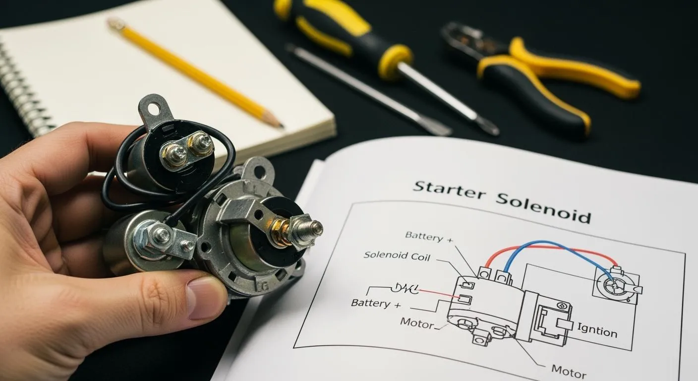
What the Schematic Shows
When you look at a starter solenoid wiring schematic, you see a clear map of how electrical connections work in your vehicle’s starting system. This schematic shows you the path electricity takes from the battery to the starter motor. You can identify each terminal and wire, which helps you understand how the starter solenoid controls the flow of current. When you turn the ignition key, a small current travels to the solenoid. The solenoid coil energizes and creates a magnetic field. This field pulls a plunger forward, pushing the starter pinion gear into the flywheel and closing heavy-duty contacts. Battery power then flows to the starter motor, which cranks the engine.
Tip: Always check the schematic before you start any wiring work. This step prevents mistakes and keeps your vehicle safe.
A starter solenoid wiring schematic also highlights the main terminals and their functions. You see where the battery connects, where the starter motor receives power, and how the ignition switch triggers the solenoid. This visual guide helps you avoid confusion and ensures you make the right connections.
Why the Schematic Matters
You need to understand the starter solenoid wiring schematic because it protects your vehicle and keeps the starting system reliable. The schematic isolates high current until the starting process begins. This safety feature prevents damage to wiring and other electrical parts. If you follow the schematic, you avoid high current surges and reduce the risk of component failure.
Starter solenoid wiring diagrams can differ based on whether a starter relay is present. Diagrams without a relay show a direct connection from the ignition switch to the solenoid. Diagrams with a relay illustrate how the relay controls solenoid activation. You must know which diagram fits your vehicle to wire the system correctly.
Here is a simple table showing the main terminals you will find in a starter solenoid wiring diagram:
| Terminal Type | Description |
|---|---|
| Battery Terminal (BAT) | Connects to the positive battery post, supplying high current for starting. |
| Starter Terminal (S) | Feeds power to the starter motor when the solenoid engages. |
| Ignition Terminal (I) | Receives control signal from the ignition switch, triggering solenoid activation. |
| Ground Connection | Completes the circuit through the vehicle chassis or engine block, essential for operation. |
You gain confidence when you use the starter solenoid wiring schematic as your guide. This knowledge helps you troubleshoot problems and keeps your starter working smoothly.
Starter Solenoid Wiring Diagram Components

Main Terminals (B, S, M)
When you look at a starter solenoid wiring diagram, you will notice three main terminals. These terminals play a key role in how the starter solenoid works. The "B" terminal, also called the battery terminal, connects directly to the positive post of your battery. This terminal carries the high current needed to start your engine. The "S" terminal, or starter terminal, receives the signal from the ignition switch. When you turn the key, this terminal activates the solenoid. The "M" terminal, sometimes labeled as the motor terminal, sends power from the solenoid to the starter motor.
You can use the table below to match each terminal with its typical wire color. This helps you identify the correct wires when you follow a wiring diagram:
| Terminal | Wire Color |
|---|---|
| Large Battery Terminal | Red |
| 'S' Terminal | Purple |
| 'R' Terminal | Yellow |
Tip: Always double-check wire colors and terminal labels before making any connections. This step prevents wiring mistakes and keeps your starter solenoid safe.
Key Symbols and Parts
A starter solenoid wiring diagram uses symbols to show each electrical part. You need to know these symbols to read the diagram correctly. The main parts you will see include:
- Battery Terminal (BAT or B+): Supplies high current for starting.
- Starter Terminal (S or START): Sends power to the starter motor.
- Ignition Terminal (I or IGN): Receives the control signal from the ignition switch.
- Ground Connection: Completes the circuit through the chassis or engine block.
- Actuator: Connects the electrical contacts inside the solenoid.
- Contact Force: Controlled by a spring, it affects how well the contacts work.
- Return Spring: Pushes the plunger back when the solenoid turns off.
- High-Current Connections: Strong terminals that handle large amounts of current.
- Coil Windings: Create a magnetic field to move the plunger.
- Plunger: Moves to close the circuit and allow electricity to flow.
- Electrical Contacts: Include one moving and two fixed contacts.
Understanding these parts helps you follow the starter solenoid wiring diagram and make safe, accurate connections.
Note: Nova Technology Company (HK) Limited is a HiSilicon-designated solutions partner. In the integrated circuit industry, they provide chip-level solutions and system integration for advanced automotive and industrial applications. Their expertise supports reliable electronic systems, including those found in starter solenoid control modules.
Reading a Starter Solenoid Wiring Schematic
Understanding how to read a starter solenoid wiring schematic helps you make safe and accurate connections. You can avoid mistakes and keep your vehicle’s electrical system working well. This section will guide you through the process of identifying wires and terminals, as well as understanding the function of each wire in the starter solenoid circuit.
Identifying Wires and Terminals
When you look at a starter solenoid wiring schematic, you will see different terminals and wires. Each terminal has a specific job. You need to match each wire to the correct terminal to make sure the starter solenoid works as it should.
Here is a table to help you identify the main wires and terminals you will find in a typical starter solenoid wiring schematic:
| Terminal Type | Connection Description |
|---|---|
| Thick Terminal 1 | Connected to the car battery. |
| Thick Terminal 2 | Connected to the field winding inside the starter via the conducting plate. |
| Thin Terminal 1 | Pull-in terminal connected to the sucking coil and holding coil. |
| Thin Terminal 2 | Connected directly to the shrapnel inside the motor, serving as the ignition switch terminal. |
You can use this table as a quick reference when you work with a starter solenoid wiring schematic. Always check the labels and wire thickness. Thick wires usually carry high current, while thin wires handle control signals.
Tip: Before you start any wiring, compare the schematic to the actual parts in your vehicle. This step helps you spot any differences and prevents wiring errors.
Wire color codes also help you read a starter solenoid wiring schematic. Many diagrams use standard colors for different wires. For example, red often shows the battery connection, purple may show the starter signal, and yellow can mark the ignition switch. These color codes make it easier to trace each wire and confirm you have the right connections.
- A starter solenoid acts as a heavy-duty relay for high electrical currents.
- The wiring diagram illustrates electrical pathways and terminal connections.
- Incorrect wiring can lead to serious issues such as burned ignition switches and fire hazards.
If you ever feel unsure, take a photo of your wiring before you disconnect anything. This simple step gives you a backup to check your work later.
Understanding Wire Functions
Each wire in the starter solenoid circuit has a unique function. Knowing what each wire does helps you troubleshoot problems and make repairs. The table below explains the typical functions of each wire you will see in a starter solenoid wiring schematic:
| Wire Type | Function |
|---|---|
| Battery Terminal | Connects to the positive battery post, supplying high current for starting. |
| Starter Terminal | Feeds power to the starter motor when the solenoid engages. |
| Ignition Terminal | Receives control signal from the ignition switch to activate the solenoid. |
| Ground Connection | Completes the circuit through the chassis or engine block. |
The battery terminal brings power from the battery to the solenoid. The starter terminal sends power to the starter motor when you turn the key. The ignition terminal receives a signal from the ignition switch, which tells the solenoid to activate. The ground connection completes the circuit and allows current to flow back to the battery.
If you want to know how to test a starter solenoid, you can use a multimeter to check for voltage at each terminal. This test helps you find out if the solenoid is getting power and working correctly. If you ever need to know how to jump a starter solenoid, you can use a jumper wire to connect the battery terminal to the starter terminal. This method can help you start the engine in an emergency, but you should only use it as a temporary fix.
Reading a starter solenoid wiring schematic gives you the skills to wire, test, and troubleshoot your starter system. You can keep your vehicle safe and reliable by following the correct steps and understanding each part of the circuit.
Starter Solenoid Wiring Steps
Preparation and Safety
You need to prepare carefully before you start wiring a starter solenoid. Safety comes first. You protect yourself and your vehicle by following these steps. Always check the wiring diagram and make sure you understand each connection.
Tip: Disconnect the negative terminal of the battery before you begin any electrical work. This step prevents electrical shocks and protects the vehicle’s electrical system.
You should secure your vehicle so it does not move during the process. Use chokes on the front and back tires. Lift your car with a jack and add a jack stand for extra security. Mark each wire with masking tape and a marker. This helps you remember where each wire goes when you reconnect them.
Here are important safety precautions to follow:
- Disconnect the negative battery terminal.
- Use wheel chokes to prevent the vehicle from rolling.
- Lift the vehicle with a jack and secure it with a jack stand.
- Mark wires before disconnecting them.
- Wear gloves and safety glasses.
You avoid accidents and electrical damage when you follow these steps. You also make the wiring process easier and safer.
Step-by-Step Wiring Process
You need to follow the schematic closely to make correct connections. This prevents high current surges and protects your starter solenoid from damage. Proper cable sizing and clean connections are crucial. Poor or corroded connections can cause overheating and heat build-up. Using a larger starter lead can help reduce the risk of overheating and ensure safe operation.
Follow this step-by-step process to wire a starter solenoid:
- Secure your vehicle with wheel chokes and disconnect the negative battery terminal.
- Lift your car using a jack and place a jack stand underneath for safety.
- Mark each wire with masking tape and a marker. Disconnect the wires from the solenoid.
- Remove the starter motor by unbolting it carefully.
- Remove the nut from the starter solenoid terminal.
- Dismount the terminal of the battery cable from the starter.
- Remove the nut from the starter solenoid terminal S.
- Remove the retaining bolts from the starter.
- Take out the starter.
- Unscrew the retaining nut of the solenoid terminal.
- Reconnect the wires to the new solenoid according to the labels.
- Reconnect the negative battery terminal.
Note: Always check the wiring diagram before reconnecting wires. This step ensures you make the correct connections and prevents mistakes.
You need to inspect each connection for corrosion or damage. Clean the terminals if needed. Tighten all nuts and bolts securely. You can use a multimeter to check voltage at each terminal. This helps you learn how to test a starter solenoid and confirm it works correctly.
If you ever need to know how to jump a starter solenoid, you can use a jumper wire to connect the battery terminal to the starter terminal. This method can help you start the engine in an emergency. Only use this as a temporary fix.
You protect your starter and electrical system when you follow these steps. You avoid high current surges and keep your vehicle safe. You gain confidence by using the schematic as your guide.
Common Mistakes and Troubleshooting
Frequent Wiring Errors
You can avoid many problems with your starter solenoid by learning about common wiring mistakes. These errors often cause current surges, damage to the solenoid switch, or even prevent your vehicle from starting. The table below lists the most frequent mistakes and explains why they matter:
| Mistake Description | Explanation |
|---|---|
| Incorrect wire gauge | Using a wire that is too small for the activation wire can cause overheating and damage. |
| Poor grounding | Failing to use a dedicated ground can lead to electrical issues and weak solenoid switch action. |
| Inadequate main starter wire | A main wire that is not strong enough may not deliver enough power to the solenoid switch, causing starting issues. |
You should always check the wire size and make sure the ground connection is solid. If you use the wrong wire or skip the ground, the solenoid switch may not work as designed.
Troubleshooting Tips
You can spot signs of incorrect starter solenoid wiring by paying attention to how your solenoid switch behaves. Here are some common signs:
- Nothing happens when you turn the key. The solenoid switch may not receive power.
- You hear a single click. The solenoid switch tries to engage but may be stuck.
- Repeated clicking sounds can mean a dead battery or a faulty solenoid switch.
- The engine starts without turning the key. This is a dangerous sign of a bad solenoid switch.
- The starter engages but does not disengage, which can cause serious damage.
- Intermittent starting points to a failing solenoid switch.
If you notice these issues, you can follow these steps to troubleshoot your solenoid switch:
- Turn off your vehicle and disconnect the negative battery terminal for safety.
- Locate the solenoid switch, usually found on the starter motor.
- Clean all terminals with a wire brush to ensure good contact.
- Use a multimeter to check for battery voltage at the solenoid switch.
- Test the solenoid switch by measuring resistance across its terminals.
- Check continuity while turning the ignition key to the "Start" position.
- Inspect the solenoid switch for visible damage or loose connections.
- If you cannot find the problem, ask a qualified mechanic for help.
Tip: Always use the right tools, such as a multimeter, wrenches, and a wire brush, when working on your solenoid switch. Good tools help you find and fix problems quickly.
You can keep your starter solenoid and solenoid switch working well by following these steps. Careful wiring and regular checks prevent most issues and keep your vehicle reliable.
You now understand how a starter solenoid wiring schematic helps you install and maintain your starter solenoid safely. When you follow the schematic, you avoid confusion about wire connections and ensure your starter and engine starter motor work reliably.
- Always select and install the correct starter solenoid for your system.
- Disconnect the battery before wiring and check each connection twice.
- Clean and tight connections prevent rust and power loss.
- Regular maintenance and high-quality parts keep your starter solenoid dependable.
If you feel unsure, ask for help or practice with guidance. You can master starter solenoid wiring with patience and attention to detail.
FAQ
What does a starter solenoid do?
You use a starter solenoid to control the flow of electricity from the battery to the starter motor. It acts like a switch that helps your engine start when you turn the ignition key.
How can I tell if my starter solenoid is bad?
You may hear clicking sounds or nothing at all when you turn the key. The engine may not crank. You should check the wiring and connections first before replacing the solenoid.
Can I wire a starter solenoid without a diagram?
You should not wire a starter solenoid without a diagram. The schematic helps you make safe and correct connections. Mistakes can damage your electrical system or cause safety risks.
What tools do I need to wire a starter solenoid?
You need a wrench, a wire brush, a multimeter, and masking tape. These tools help you disconnect wires, clean terminals, test voltage, and label connections for easy reassembly.
Why does my starter motor keep running after the engine starts?
You may have a stuck solenoid or a wiring problem. This issue can damage the starter motor. You should disconnect the battery and check the wiring and solenoid for faults.