How to Identify Potentiometer Symbols in Schematics
The symbol of a potentiometer in schematics shows a resistor with an angled arrow and three terminals, indicating its adjustable function in electronic hardware.
You can identify the symbol of a potentiometer in schematics by looking for a resistor symbol with an arrow crossing it at an angle. This arrow shows that the potentiometer is adjustable and highlights its three-terminal design. Recognizing this symbol is essential for understanding electronic hardware because:
- You learn how adjustable components work, which leads to accurate circuit interpretation.
- This knowledge helps you design circuits that meet your needs.
- Mastering potentiometer symbols improves your troubleshooting skills and lets you optimize circuit performance.
The symbol of a potentiometer also changes depending on the standard or variant, so knowing these differences ensures correct identification.
Key Takeaways
- Identify potentiometer symbols by looking for a resistor with an arrow crossing it. This arrow indicates adjustability.
- Recognize that potentiometers have three terminals: two for the resistor ends and one for the adjustable wiper.
- Understand the difference between ANSI and IEC symbol styles to avoid confusion in circuit diagrams.
- Use potentiometers in various applications like volume controls and light dimmers to adjust electrical signals effectively.
- Practice identifying potentiometer symbols in real schematics to enhance your circuit reading skills and reduce errors.
What Is a Potentiometer in Electronics?
Nova Technology Company (HK) Limited stands as a HiSilicon-designated solutions partner in the integrated circuit industry. You benefit from their expertise in chip-level solutions, system integration, and advanced application scenarios. Their professional approach supports semiconductor projects, especially when you work with complex hardware like potentiometers.
Potentiometer Function and Applications
You encounter the potentiometer in electronics as a three-terminal adjustable resistor. Standard textbooks define a potentiometer as a device that provides a variable voltage output. The function of a potentiometer centers on its ability to change resistance and control voltage in a circuit. You use the function of a potentiometer to adjust settings in many devices.
The function of a potentiometer gives you precise control over electrical signals.
You find potentiometers in several common applications:
- Volume controls: You adjust audio levels in speakers and amplifiers using the function of a potentiometer.
- Light dimmers: You change brightness by varying resistance.
- Position sensors: You see potentiometers in joysticks and automotive throttle sensors.
The function of a potentiometer makes it essential for both simple and advanced electronic systems.
Three-Terminal Structure Explained
You recognize the three-terminal structure as a key feature of the potentiometer. The function of a potentiometer relies on these terminals:
- Two outer terminals connect to the ends of a resistive element.
- The middle terminal attaches to a movable wiper.
The wiper slides along the resistive element, dividing it into two sections. This movement lets you adjust resistance and voltage output. When you use the function of a potentiometer as a voltage divider, you select a fraction of the input voltage based on the wiper’s position.
| Terminal | Connection | Role |
|---|---|---|
| 1 | End of resistive element | Input/Output |
| 2 | Wiper (middle) | Adjustable Output |
| 3 | Other end of resistive element | Input/Output |
You see that the three-terminal design supports the adjustable nature and versatility of the potentiometer in electronics.
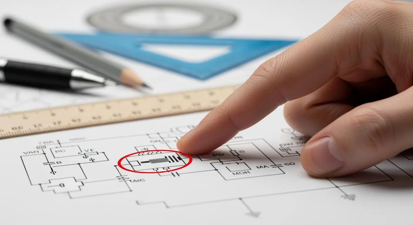
Understanding the Symbol of a Potentiometer

When you read a schematic, you often see the symbol of a potentiometer. This symbol helps you understand how the component works in a circuit. The basic structure shows a resistor with an arrow crossing it at an angle. The arrow stands for the adjustable wiper. This wiper moves along the resistive track, which lets you change the resistance and voltage output. The symbol of a potentiometer always shows three terminals. Two terminals connect to the ends of the resistor, and the third connects to the wiper. This design tells you that the potentiometer can divide voltage and adjust signals.
Potentiometer Symbol in ANSI and IEC Standards
You will find two main standards for the symbol of a potentiometer: ANSI and IEC. Each standard uses a different style, but both show the adjustable and three-terminal nature of the device.
| Standard | Symbol Representation |
|---|---|
| ANSI | Two straight lines with zigzag lines in between (zigzag resistor with arrow) |
| IEC | A rectangle between two straight lines (rectangular resistor block with arrow) |
The ANSI style uses a zigzag line to show the resistor. The IEC style uses a rectangle. Both symbols include an arrow that points to the middle of the resistor. This arrow shows the wiper, which you can move to adjust the resistance. You see the ANSI symbol in older or American schematics. The IEC symbol appears in modern and international diagrams, especially in CAD software.
Using non-standard potentiometer symbols can create confusion about how the potentiometer operates, especially concerning the wiper's movement. This confusion may lead to incorrect wiring and functionality in the circuit design. By including indicators like 'CW' and 'CCW' on the schematic, designers can better understand the physical behavior of the potentiometer, reducing the risk of errors during the design process.
Key Differences and Common Variants
You may notice several variants of the symbol of a potentiometer in schematics. Each variant gives you clues about how the potentiometer works or how you should use it.
| Symbol Style | Appearance | Typical Meaning |
|---|---|---|
| ANSI style | Zigzag resistor with arrow | Traditional resistor-style drawing used in many legacy schematics |
| IEC style | Rectangular resistor block with arrow | Common in international and modern CAD environments |
| Trim potentiometer | Potentiometer symbol with adjustment indication | Used for calibration or preset tuning rather than frequent user adjustment |
| Dual-gang potentiometer | Two linked pot sections | Two channels adjusted together, often used in stereo circuits |
| Rheostat configuration | Potentiometer used with only two terminals | Same part, but functioning as a variable resistor |
You can spot the trim potentiometer by a small line or mark that shows it is for fine adjustments. The dual-gang potentiometer has two sections linked together, which lets you control two signals at once. When you see only two terminals used, the potentiometer works as a rheostat, which means it acts as a variable resistor.
The symbol of a potentiometer always includes an arrow to show the adjustable wiper. This arrow is important because it tells you that you can change the resistance. The three-terminal structure in the symbol matches the real device. Two terminals connect to the ends of the resistor, and the third connects to the wiper. This setup lets you use the potentiometer as a voltage divider or as a variable resistor.
You should always check which symbol style appears in your schematic. If you see a rectangle with an arrow, you are looking at the IEC style. If you see a zigzag line with an arrow, you are seeing the ANSI style. Both symbols mean the same thing, but the style tells you which standard the designer followed.
Identifying Potentiometer Symbols in Schematics

Spotting Symbol Variations
You can identify a potentiometer in a schematic by looking for three main features. First, find a resistor symbol with an arrow crossing it. The arrow always points toward the resistor element. This arrow shows that the component is adjustable. The symbol also displays three terminals. Two terminals connect to the ends of the resistor, and the third connects to the arrow, which represents the wiper. This wiper slides along the resistive element and divides the voltage. You see this design in both ANSI and IEC standards.
When you compare potentiometers to other adjustable resistors, you notice that the potentiometer always has an arrow and three terminals. Variable resistors, like rheostats, usually show only two terminals. The arrow in the potentiometer symbol means you can use it as an adjustable voltage divider. This feature supports many practical applications of potentiometers, such as volume controls and light dimmers.
Here is a quick reference table to help you spot the differences:
| Component Type | Key Features |
|---|---|
| Potentiometer | Rectangle or zigzag with arrow; three terminals |
| Variable Resistor | Rectangle or zigzag; usually two terminals |
You should always check the context of the application. If you see the symbol in a circuit for audio or sensor adjustment, you are likely looking at a potentiometer. The adjustable nature of the symbol matches the functions of a potentiometer in physics, where you control voltage and resistance.
Troubleshooting Symbol Confusion
You may sometimes confuse potentiometer symbols with other adjustable resistors. To avoid mistakes, follow these steps:
- Check for the arrow. The arrow always means the component is adjustable.
- Count the terminals. Potentiometers have three terminals. Other adjustable resistors often have only two.
- Look at the arrow’s shape. Standard potentiometers use a straight arrow, while trimmer potentiometers may use a “T”-shaped arrow.
- Review the application in the schematic. If the component acts as an adjustable voltage divider, it is a potentiometer.
If you still feel unsure, use these troubleshooting tips:
- Use a multimeter to check the resistance between terminals. The total resistance between the two end terminals should match the rated value. The resistance between the wiper and each end terminal should change smoothly as you adjust the knob.
- Inspect for mechanical wear or damage if the resistance does not change as expected.
- Beginners often mix up the wiper terminal with a fixed terminal. Always remember, the arrow points to the adjustable wiper.
By following these steps, you can confidently identify potentiometer symbols and understand their functions of a potentiometer in physics. This skill helps you read schematics and apply practical applications of potentiometers in real circuits. You will also recognize how the adjustable voltage divider supports many electronic designs.
You can identify a potentiometer symbol by finding three terminals and an arrow pointing to the adjustable wiper. Understanding the role of potentiometers helps you read circuit diagrams with confidence. Practice by reviewing real-world schematics to improve your skills. Mastering potentiometer symbols lets you select components accurately and avoid mistakes. The table below shows how symbol variations affect circuit interpretation:
| Potentiometer Symbol | Description |
|---|---|
| Three connected terminals | Adjustable voltage divider |
| Two connected terminals | Variable resistor |
Practicing symbol recognition reduces errors and helps you troubleshoot circuits faster.
FAQ
What does a potentiometer do in electronics?
You use a potentiometer to adjust voltage or signal levels in electronics. The device changes resistance, which lets you control the output. This function is important for tuning circuits, setting audio volume, or adjusting brightness in many electronic devices.
How do you identify a potentiometer symbol in a schematic?
You spot a potentiometer symbol by finding a resistor with an arrow crossing it. The symbol always shows three terminals. This design helps you understand the adjustable function and the role of the potentiometer in electronics.
Why are potentiometers important in electronics labs?
You rely on potentiometers in electronics labs to test, calibrate, and fine-tune circuits. The adjustable function lets you set exact values for voltage or current. This makes experiments and troubleshooting easier for anyone learning about electronics.
What are common potentiometer uses in physics experiments?
You see potentiometer uses in physics when you need to measure unknown voltages or create voltage dividers. The function of the potentiometer helps you control and compare electrical signals in basic electronics experiments.
Can you use a potentiometer as a variable resistor?
Yes, you can use a potentiometer as a variable resistor in electronics. You connect only two terminals. This setup changes the function, so the potentiometer controls current instead of dividing voltage.
Tip: Always check the schematic to see how the potentiometer connects. This helps you understand its function in the circuit.