Designing a High-Performance Op Amp Circuit: A Step-by-Step Guide for Engineers
Expert guide on Designing a High-Performance Op Amp Circuit: A Step-by-Step Guide for Engineers. Technical specs, applications, sourcing tips for engineers and buyers.
Introduction
Designing high-performance operational amplifier (op amp) circuits is a fundamental skill for electronics engineers. With applications ranging from audio equipment to signal processing and instrumentation, op amps are integral to modern electronics. As the semiconductor industry continues to grow, with global revenues predicted to reach $595.2 billion by 2026, the demand for efficient and reliable op amp designs is higher than ever. This article will guide you through the process of designing a high-performance op amp circuit, focusing on process parameters, equipment requirements, and quality control measures.
Technical Overview
Operational amplifiers are versatile components used to amplify voltage, with applications in filtering, voltage regulation, and analog computing. A typical op amp circuit consists of an inverting and a non-inverting input, an output, and feedback mechanisms to control gain and stability. Key performance metrics include gain bandwidth product, slew rate, input offset voltage, and noise performance. Understanding these parameters is crucial for optimizing circuit performance and ensuring reliability in various operational conditions.
The selection of components, such as resistors and capacitors, and their precise values, plays a significant role in determining the overall performance of the op amp circuit. Additionally, considerations such as power supply voltage, load resistance, and thermal management are essential to prevent circuit failure and ensure longevity.
Detailed Specifications
| Parameter | Specification | Units | Tolerances | Notes |
|---|---|---|---|---|
| Gain Bandwidth Product | 10 MHz | Hz | ±5% | Higher is better for wide bandwidth applications |
| Slew Rate | 20 V/µs | V/µs | ±2% | Important for fast signal amplification |
| Input Offset Voltage | 2 mV | mV | ±0.5 mV | Lower values reduce error in DC applications |
| Input Bias Current | 10 nA | nA | ±1 nA | Critical for high impedance circuits |
| Output Impedance | 75 Ω | Ω | ±10% | Influences load driving capability |
| Power Supply Voltage | ±15 V | V | ±0.5 V | Dual supply for bipolar operation |
| Common Mode Rejection Ratio | 80 dB | dB | ±5 dB | Higher values indicate better noise rejection |
| Power Supply Rejection Ratio | 90 dB | dB | ±5 dB | Indicates stability against supply voltage variations |
| Thermal Resistance | 100 °C/W | °C/W | ±10 °C/W | Influences thermal management |
| Total Harmonic Distortion | 0.005% | % | ±0.001% | Lower values are preferable for audio applications |
| Equipment/Tool | Specification | Notes |
|---|---|---|
| Oscilloscope | 200 MHz bandwidth, 4 channels | Essential for waveform analysis |
| Function Generator | 20 MHz frequency range | For signal input testing |
| Multimeter | True RMS, 0.1% accuracy | Used for voltage, current, and resistance measurements |
| Soldering Station | Temperature controlled, 50 W | For assembling circuit components |
| PCB Layout Software | Altium Designer or Eagle | For designing circuit boards |
| Power Supply | Dual output, 0-30 V, 3 A | Provides necessary power for the circuit |
| Logic Analyzer | 16 channels, 200 MHz | For analyzing digital signals |
| Thermal Imaging Camera | Resolution: 320x240 pixels | For thermal management analysis |
| Spectrum Analyzer | 1 GHz frequency range | Used for frequency domain analysis |
| Issue | Solution | Notes |
|---|---|---|
| Oscillation in Output | Increase feedback capacitance | Check for proper phase margin |
| Excessive Noise | Use low-noise components | Ensure proper grounding |
| Thermal Overload | Add heat sinks or fans | Check power dissipation |
| Offset Voltage Drift | Use chopper-stabilized op amps | Consider temperature compensation |
| Insufficient Bandwidth | Select op amps with higher GBW | Evaluate application requirements |
| Component Failure | Verify component ratings | Perform regular inspections |
Design Considerations
Designing a high-performance op amp circuit requires careful consideration of various factors to ensure optimal functionality and reliability. The selection of the op amp itself is crucial, with parameters like gain bandwidth product and slew rate playing a significant role in determining the circuit's performance. For example, an op amp with a higher gain bandwidth product is better suited for applications requiring wide bandwidth and fast response times.
Thermal management is another critical aspect, as op amps can generate significant heat, especially in high-power applications. Implementing adequate cooling solutions, such as heat sinks or thermal pads, can prevent thermal overload and extend the lifespan of the components. Additionally, ensuring proper PCB layout and grounding can minimize noise and interference, which is essential for maintaining signal integrity.
Component tolerances and matching are also vital considerations. Using precision resistors and capacitors with tight tolerances can significantly reduce errors and improve the overall accuracy of the circuit. Furthermore, feedback network design is crucial for stability, with the choice of feedback resistors and capacitors affecting the phase margin and susceptibility to oscillations.
Finally, power supply considerations, such as voltage levels and filtering, are essential to ensure stable operation. Using power supply rejection techniques and decoupling capacitors can mitigate the impact of supply voltage variations and noise on the op amp's performance.
Step-by-Step Guide
- Define the Application Requirements: Identify the specific requirements of your application, such as gain, bandwidth, and input/output voltage levels. This will guide the selection of the appropriate op amp and supporting components.
- Select the Op Amp: Choose an op amp that meets your application's specifications. Consider parameters like gain bandwidth product, slew rate, and input offset voltage. For example, the OPA2134 is a popular choice for audio applications due to its low noise and distortion.
- Design the Feedback Network: Calculate the values of feedback resistors and capacitors to achieve the desired gain and stability. Ensure the phase margin is sufficient to prevent oscillations.
- Simulate the Circuit: Use circuit simulation software to model the op amp circuit. Verify the performance against your design specifications and make adjustments as necessary.
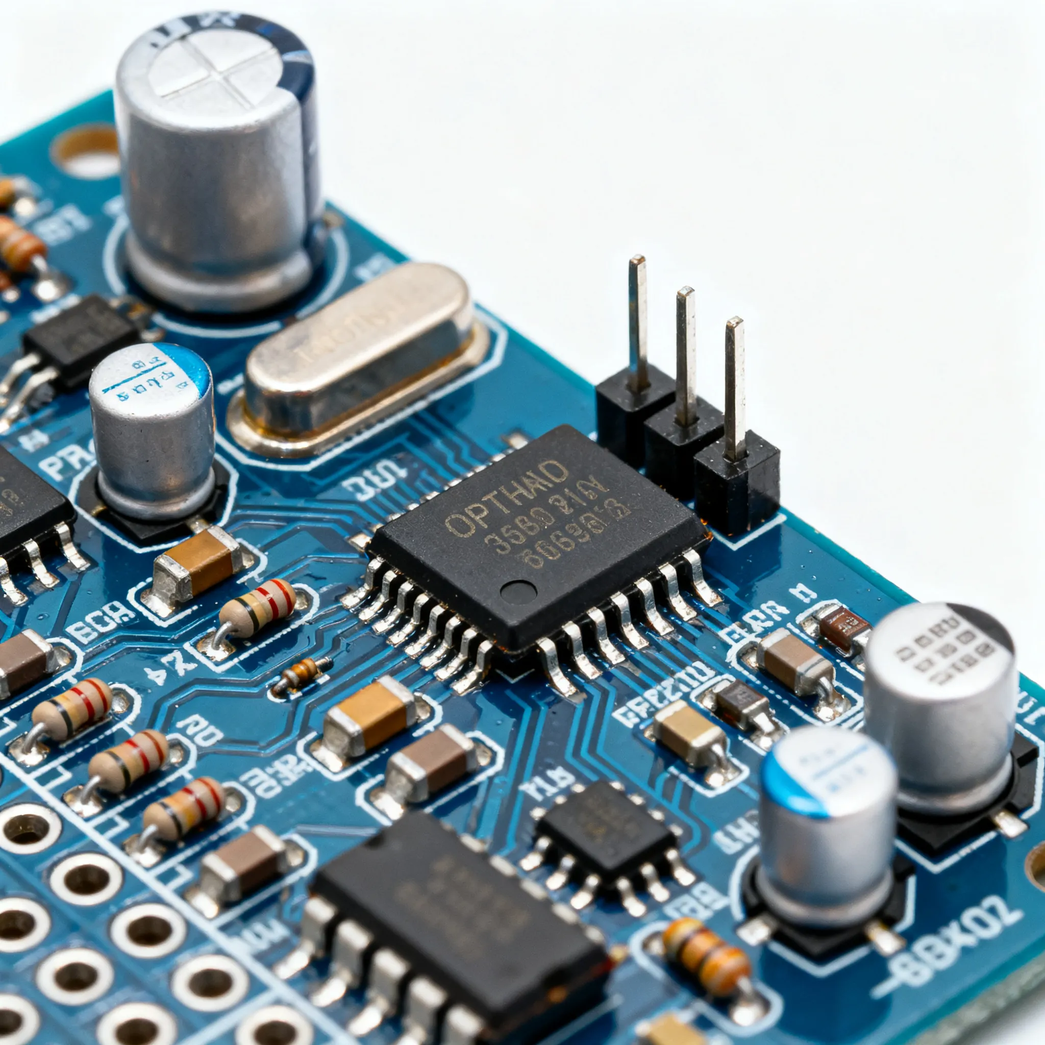
- Assemble the Circuit: Construct the circuit on a breadboard or PCB. Pay attention to the layout, ensuring proper grounding and minimizing parasitic inductance and capacitance.
- Test and Validate: Use test equipment, such as an oscilloscope and multimeter, to verify the circuit's performance. Check parameters like gain, bandwidth, and noise levels to ensure they meet the design requirements.
- Implement Thermal Management: Add heat sinks or thermal pads if necessary to manage heat dissipation. Use a thermal imaging camera to identify hotspots and ensure even temperature distribution.
- Final Adjustments and Documentation: Make any necessary adjustments based on testing results and document the final design, including schematics and component lists, for future reference and replication.
Common Issues & Solutions
Designing op amp circuits can present various challenges. Here are some common issues and their solutions:
- Oscillation in Output: This can occur due to insufficient phase margin. Increasing the feedback capacitance or adjusting the feedback network can help stabilize the circuit.
- Excessive Noise: Noise can degrade performance, especially in audio applications. Using low-noise components and ensuring proper grounding and shielding can mitigate this issue.
- Thermal Overload: High power dissipation can lead to thermal overload. Implementing heat sinks or fans and ensuring adequate ventilation can prevent overheating.
- Offset Voltage Drift: Temperature variations can cause offset voltage drift, impacting accuracy. Using chopper-stabilized op amps or temperature compensation techniques can address this problem.
- Component Failure: Components can fail due to over-voltage or over-current conditions. Verifying component ratings and performing regular inspections can help prevent failures.
Applications & Use Cases
High-performance op amp circuits are used in a wide range of applications, including:
- Audio Equipment: Op amps are used in preamplifiers, equalizers, and audio mixers to amplify and shape audio signals.
- Instrumentation: Precision op amp circuits are employed in measurement and test equipment for accurate signal processing.
- Signal Processing: Op amps are used in filters, integrators, and differentiators in analog signal processing applications.
- Medical Devices: Op amps are used in medical instrumentation for signal conditioning and amplification in devices like ECG and EEG machines.
Selection & Sourcing Guide
Selecting the right components is crucial for designing a reliable op amp circuit. Utilize resources like IC Online to source high-quality components at competitive prices. Ensure that the components meet the design specifications and are from reputable manufacturers to guarantee performance and reliability.
FAQ
- What is an operational amplifier? An operational amplifier is a high-gain electronic voltage amplifier with differential inputs and, usually, a single-ended output used in various applications for signal amplification.
- How do I choose the right op amp for my application? Consider parameters like gain bandwidth product, slew rate, noise performance, and power supply requirements. Match these to your application's specifications.
- What is gain bandwidth product? Gain bandwidth product is the product of the amplifier's bandwidth and the gain at which it operates. It is a key parameter in determining the op amp's frequency response capabilities.
- How can I prevent oscillations in my op amp circuit? Ensure sufficient phase margin by designing an appropriate feedback network and using compensation techniques like adding a feedback capacitor.
- What causes thermal overload in op amp circuits? Thermal overload can be caused by excessive power dissipation. Implementing proper thermal management techniques, such as using heat sinks, can mitigate this issue.
- What is input offset voltage? Input offset voltage is the differential DC voltage required between the inputs to make the output zero. It is a critical parameter in precision applications.
- How do I measure op amp circuit performance? Use test equipment like oscilloscopes and multimeters to measure parameters such as gain, bandwidth, and noise levels.
- What are some common applications of op amps? Op amps are widely used in audio equipment, instrumentation, signal processing, and medical devices for various signal amplification and conditioning tasks.
- How can I reduce noise in my op amp circuit? Use low-noise components, proper grounding techniques, and shielding to minimize noise and interference in your circuit.
Conclusion
Designing a high-performance op amp circuit requires a comprehensive understanding of op amp specifications, careful component selection, and meticulous design practices. By following the guidelines outlined in this article, engineers can create reliable and efficient op amp circuits for a variety of applications. As the demand for advanced electronics continues to grow, mastering op amp design will remain an essential skill in the field of electronics engineering.