IGBT vs MOSFET for Solar Inverter Designs: An Industrial Application Case Study
Expert guide on IGBT vs MOSFET for Solar Inverter Designs: An Industrial Application Case Study. Technical specs, applications, sourcing tips for engineers and buyers.
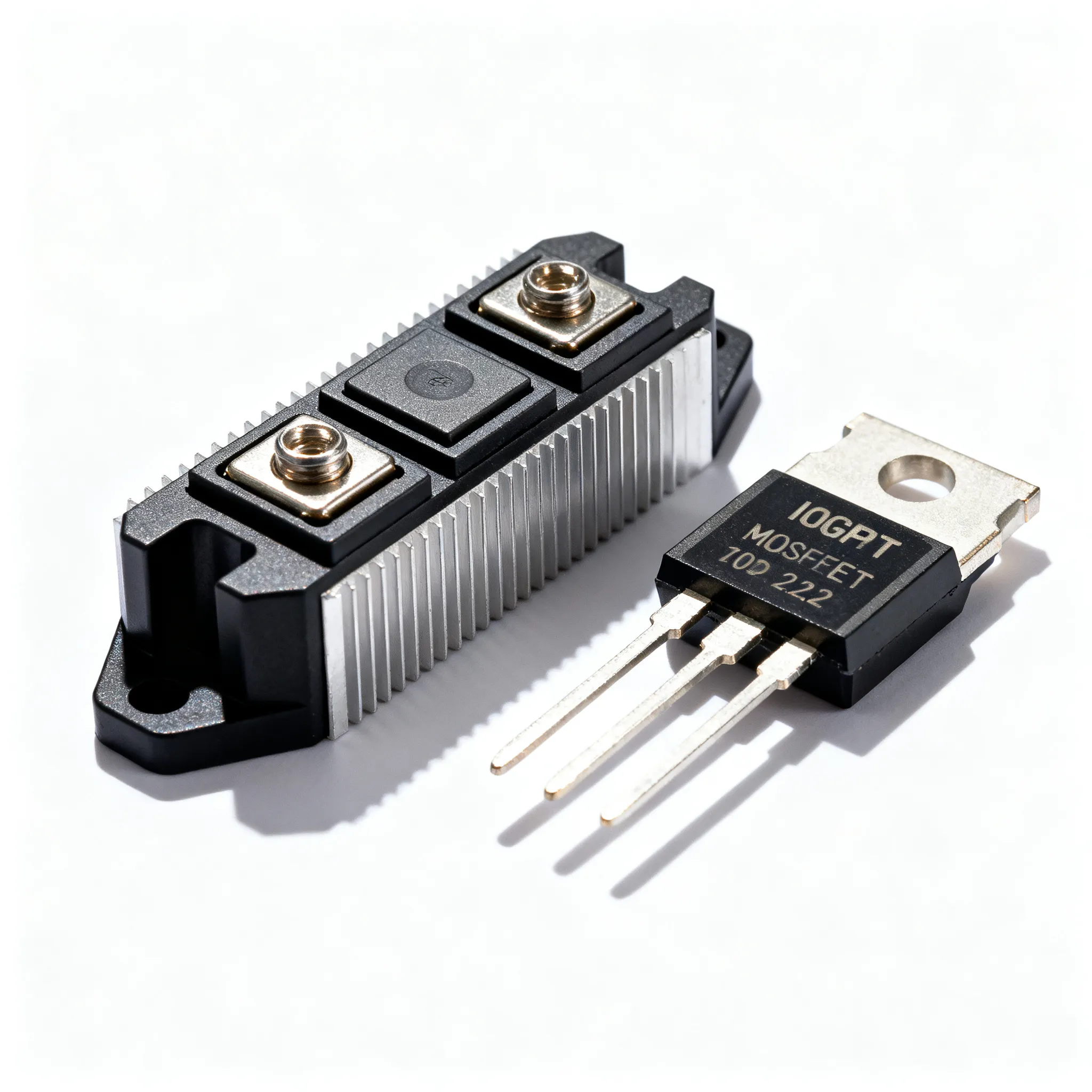
Why Solar Inverter Designers Are Revisiting the IGBT vs MOSFET Decision
The solar inverter market is undergoing a quiet but consequential shift. Efficiency targets for residential and commercial systems keep climbing—CEC and EU weighted efficiency numbers now routinely exceed 98%—while power density demands push designers toward higher switching frequencies and smaller magnetics. At the same time, supply chain volatility has made long-term component availability a boardroom-level concern. These pressures are forcing engineering teams to re-examine a decision that, for years, felt settled: the choice between silicon IGBTs and silicon MOSFETs in the power stage.
For utility-scale central inverters, high-voltage IGBT modules remain the workhorse, but the landscape is fragmenting. Wide-bandgap alternatives, particularly silicon carbide (SiC) MOSFETs, are blurring the traditional voltage and frequency boundaries. Yet silicon devices still account for the vast majority of solar inverter bill-of-materials (BOM) spend, as noted in recent industry coverage by EE Times. The question is no longer simply “IGBT or MOSFET?” but rather “Which device, in which stage, and at what cost?”
This article provides an industrial case-study perspective, grounded in real-world inverter topologies and procurement realities. We’ll walk through the fundamental loss mechanisms, compare device performance in single-phase and three-phase architectures, and offer practical selection criteria that balance technical performance with supply chain resilience.
Switching Losses, Conduction Behavior, and Thermal Limits in PV Inverter Topologies
To understand the trade-offs, you need to look at what happens inside the semiconductor during each switching cycle. IGBTs are minority-carrier devices: during turn-off, stored charge in the drift region must recombine, creating a characteristic “tail current” that increases turn-off energy (Eoff) and limits practical switching frequencies to roughly 20 kHz in hard-switched solar inverters. In contrast, power MOSFETs are majority-carrier devices with no tail current, enabling switching frequencies of 50 kHz to 100 kHz and beyond. However, the MOSFET’s intrinsic body diode can exhibit reverse-recovery charge (Qrr) that causes ringing and additional losses in bridge topologies, especially when the high-side device commutates the low-side diode.
Conduction losses also follow different rules. An IGBT’s forward voltage drop (VCE(sat)) is relatively flat across a wide current range, which benefits high-current operation. A MOSFET behaves like a resistor: its on-resistance (RDS(on)) increases with temperature, typically by 50–80% between 25°C and 125°C. This positive temperature coefficient can complicate thermal design but also enables easy paralleling. The table below contrasts typical device parameters that directly influence solar inverter efficiency and thermal management.
| Parameter | 1200 V Si IGBT (IKW40N120H3) | 650 V Si SJ MOSFET (IPW65R041CFD) | 1200 V SiC MOSFET (C3M0016120K) | Unit |
|---|---|---|---|---|
| VCE(sat) / RDS(on) (25°C) | 1.7 V (typ. @ 40 A) | 41 mΩ | 16 mΩ | V / mΩ |
| VCE(sat) / RDS(on) (125°C) | 1.9 V | ~78 mΩ | ~24 mΩ | V / mΩ |
| Eon (400 V, 40 A) | 2.1 mJ | 0.15 mJ | 0.25 mJ | mJ |
| Eoff (400 V, 40 A) | 1.8 mJ | 0.08 mJ | 0.12 mJ | mJ |
| Total gate charge Qg | 203 nC | 150 nC | 118 nC | nC |
| Body diode Qrr (typ.) | N/A (co-packed diode) | 9 µC | 0.3 µC | µC |
| RthJC (max.) | 0.35 K/W | 0.45 K/W | 0.28 K/W | K/W |
| Typical switching frequency | 8–20 kHz | 50–100 kHz | 50–200 kHz | kHz |
Note: Values are typical from manufacturer datasheets; actual performance depends on gate drive design, layout parasitics, and operating temperature. The 1200 V IGBT includes a co-packed fast-recovery diode; the SiC MOSFET’s body diode exhibits negligible reverse recovery.
From this data, a few design rules emerge. For a hard-switched DC-DC boost stage in a residential string inverter, the 650 V super-junction MOSFET’s low switching losses and high frequency capability allow a smaller boost inductor and higher MPPT efficiency at partial load. The 1200 V IGBT, with its tail current, would struggle to reach 98% CEC efficiency if switched above 16 kHz. The SiC MOSFET essentially combines the best of both worlds—low conduction losses at high temperature, minimal switching energy, and a fast body diode—but at a cost premium that must be justified by system-level savings in magnetics and heatsinking.
Side-by-Side: IGBT and MOSFET Performance in Single-Phase and Three-Phase Solar Inverter Stages
Real-world solar inverters are not single-switch applications. A typical single-phase string inverter (3–10 kW) contains a front-end boost converter that tracks the maximum power point (MPPT) and a full-bridge DC-AC inverter. Three-phase commercial inverters (20–100 kW) often use a two-level or three-level voltage-source inverter topology, sometimes with an additional DC-DC stage. Device selection must consider the entire power train, not just one position.
The table below maps common device choices to inverter stages, highlighting the performance boundaries that drive the decision.
| Inverter Stage | Option A: Si IGBT | Option B: Si SJ MOSFET | Option C: SiC MOSFET | Selection Criteria & Failure Boundary |
|---|---|---|---|---|
| MPPT Boost (200–500 V → 380 V DC link) | 1200 V IGBT + SiC diode; cost-effective at <16 kHz | 650 V SJ MOSFET; excellent light-load efficiency, up to 100 kHz | 900–1200 V SiC MOSFET; overkill for most 1-phase boosts | MOSFET wins on CEC efficiency if switching above 30 kHz. IGBT tail losses become dominant above 20 kHz. SiC only needed for >600 V DC link. |
| 1-Phase DC-AC H-Bridge (230 VAC) | 600–650 V IGBT; rugged, low cost, but limited to 20 kHz | 600–650 V SJ MOSFET; lower conduction losses at partial load, faster switching | 650 V SiC MOSFET; highest efficiency, smallest filter | MOSFET preferred for fanless designs. IGBT acceptable if audible noise is not a concern. SiC justified when power density is the primary KPI. |
| 3-Phase 2-Level Inverter (400 VAC, 30 kW) | 1200 V IGBT half-bridge module; proven reliability, multiple sources | Not practical: >900 V Si MOSFETs have high RDS(on) | 1200 V SiC MOSFET module; 50% lower losses, enables higher frequency | IGBT is the default for cost-sensitive designs. SiC chosen when transformerless topology and 99% efficiency are required. Failure boundary: Si MOSFET avalanche ruggedness insufficient above 800 V DC link. |
| 3-Level NPC/T-Type (400 VAC) | 600 V IGBT for outer switches; 1200 V IGBT for clamp | 600 V SJ MOSFET for high-frequency leg; lower switching losses | 650 V SiC MOSFET for all positions; eliminates tail current entirely | Hybrid Si/SiC approach balances cost and performance. Use MOSFETs on the fast-switching inner leg, IGBTs on the slow outer leg. |
Partial shading and grid-support modes add further nuance. Under light-load conditions, the fixed VCE(sat) of an IGBT becomes a larger fraction of total losses, dragging down weighted efficiency. This is one reason many residential inverter OEMs have migrated the boost stage entirely to super-junction MOSFETs. In three-phase commercial units, hybrid Si/SiC solutions are gaining traction: a SiC MOSFET on the high-frequency PWM leg slashes switching losses, while a silicon IGBT on the low-frequency leg handles the bulk current at lower cost. This approach is documented in several reference designs from semiconductor manufacturers and aligns with the trend toward higher DC-link voltages (1000 V and 1500 V) in utility-scale systems.
Making the Call: Device Selection Criteria for Residential, Commercial, and Utility-Scale Solar Inverters
Choosing between an IGBT and a MOSFET is never a one-parameter decision. You must balance switching frequency, conduction losses, gate drive complexity, and long-term availability—all while meeting cost targets that can be razor-thin in the solar market. The following guidelines, drawn from field experience, help structure the evaluation.
Switching frequency vs. magnetics cost. If your inverter’s total harmonic distortion (THD) requirements force you above 30 kHz, a silicon IGBT will likely overheat. Super-junction MOSFETs or SiC MOSFETs become mandatory. The savings in inductor and capacitor size often offset the higher semiconductor cost, especially in residential wall-mount units where volume is at a premium.
Conduction losses at elevated temperature. Always check RDS(on) at 125°C, not 25°C. A MOSFET that looks attractive on the first page of a datasheet can double its on-resistance in a sealed outdoor enclosure. IGBTs, by contrast, show only a modest increase in VCE(sat). Use the safe operating area (SOA) curves to verify that the device can handle start-up inrush and grid-fault conditions without leaving the linear region.
Gate drive complexity. SiC MOSFETs often require a negative gate voltage for reliable turn-off and a tightly regulated +15 V to +18 V drive. Silicon IGBTs and MOSFETs are more forgiving. Factor in the cost and board space of an isolated gate driver with active Miller clamping if you opt for SiC.
Second-source and lifecycle planning. Solar inverters are expected to operate for 15–20 years. A single-sourced power semiconductor is a procurement risk. IGBT modules in standard packages (e.g., EconoPACK™, EasyPACK™) are available from multiple manufacturers—Infineon, ON Semiconductor, Fuji Electric, and others. High-voltage silicon MOSFETs above 900 V are far less common and often single-sourced. SiC MOSFETs are rapidly gaining second sources, but pin-to-pin compatibility is not yet universal. Qualify at least one drop-in alternative early in the design phase. Assembly quality per IPC-A-610 Class 3 standards is recommended for power modules in harsh outdoor environments, where thermal cycling and humidity can degrade solder joints.
The table below summarizes device recommendations by inverter class, reflecting the current industrial practice.
| Inverter Class | Power Range | DC Link Voltage | Recommended Device | Key Selection Drivers | Sourcing Notes |
|---|---|---|---|---|---|
| Residential string (1-phase) | 1–10 kW | 360–500 V | 650 V SJ MOSFET (boost + inverter) | High CEC efficiency, fanless operation, compact design | Multiple sources (Infineon, ST, ON Semi); standard packages |
| Commercial string (3-phase) | 10–60 kW | 600–800 V | 1200 V IGBT module or hybrid Si/SiC | Cost per watt, proven reliability, grid-code compliance | IGBT modules widely multi-sourced; SiC MOSFETs check pin compatibility |
| Utility-scale central | >100 kW | 1000–1500 V | 1200 V / 1700 V IGBT press-pack or module | Ruggedness, surge current capability, serviceability | Long-term supply agreements essential; plan for 20-year lifecycle |
| High-power-density hybrid | 5–20 kW | 800 V | 1200 V SiC MOSFET | Size reduction, >99% peak efficiency, low thermal budget | Emerging second sources; evaluate Wolfspeed, ST, ON Semi, Rohm |
Tip: When evaluating a MOSFET for an existing IGBT footprint, pay close attention to the thermal impedance stack-up. A MOSFET’s RDS(on) temperature coefficient can push junction temperature 15–20°C higher than an IGBT under the same cooling conditions. A 20–30% margin on Tj(max) (staying below 125°C) is a prudent starting point unless you are using advanced packaging such as topside cooling or direct-bonded copper substrates.
Field-Proven Questions: IGBT vs MOSFET in Solar Inverter Engineering
Senior engineers and procurement leads frequently raise these questions when optimizing inverter BOMs and design margins.
- Q: For a 5 kW residential string inverter, is a super-junction MOSFET or an IGBT a better fit for the DC-DC boost stage?
- Super-junction MOSFETs typically offer lower conduction losses at light loads and can switch at 50–100 kHz, which shrinks the boost inductor and reduces audible noise. IGBTs can be cost-effective if the switching frequency is kept below 20 kHz, but their tail current increases turn-off losses and limits CEC efficiency. The MOSFET’s body diode also simplifies synchronous rectification, enabling higher boost efficiency without an extra Schottky diode.
- Q: How do IGBT tail currents affect efficiency at light loads in three-phase commercial inverters?
- Tail currents cause a fixed energy loss per switching cycle, which becomes a larger percentage of total losses at low power. This erodes CEC or EU weighted efficiency ratings, which heavily weight partial-load operation. Designers often mitigate this by using fast-recovery diodes in parallel or by moving to MOSFETs for the high-frequency PWM leg. In three-level topologies, placing SiC MOSFETs on the inner switches and IGBTs on the outer switches is a common compromise.
- Q: Are there reliability concerns with using silicon MOSFETs in high-voltage DC-link applications above 800 V?
- Yes. High-voltage silicon MOSFETs rated above 900 V exhibit high on-resistance due to the JFET effect, leading to excessive conduction losses. More critically, their avalanche capability is often limited compared to IGBTs, making them less rugged during grid transients or surge events. For DC links above 800 V, most engineers prefer IGBTs or SiC MOSFETs to ensure reliable operation and avoid thermal runaway.
- Q: What is the impact of wide-bandgap devices like SiC MOSFETs on the traditional IGBT vs MOSFET debate for solar?
- SiC MOSFETs blur the boundary by offering IGBT-like voltage ratings (1200 V and 1700 V) with MOSFET-like switching speeds and a fast, low-recovery body diode. They are gaining traction in high-power-density designs where size and weight matter, but they still carry a cost premium—often 2–3× that of an equivalent silicon IGBT. The traditional silicon IGBT vs MOSFET comparison now often becomes a three-way decision that includes SiC, especially when total system cost (including cooling and magnetics) is considered.
- Q: How should procurement teams evaluate second-source availability for IGBTs and MOSFETs in solar inverter BOMs?
- Check for pin-to-pin compatible alternatives from at least two manufacturers, especially for long-lifecycle products. IGBT modules in industry-standard packages often have multiple sources (Infineon, ON Semi, Fuji Electric, StarPower, etc.), while specific high-voltage silicon MOSFETs may be single-sourced. For SiC MOSFETs, the supply base is expanding but not yet fully interchangeable. Plan qualification of substitutes early and maintain an approved vendor list (AVL) that is reviewed quarterly against lead-time trends.
- Q: What thermal design margins are recommended when replacing an IGBT with a MOSFET in an existing inverter platform?
- MOSFETs can have a higher RDS(on) temperature coefficient, so thermal derating must account for increased conduction losses at elevated junction temperatures. A 20–30% margin on junction temperature (staying below 125°C) is advisable unless using advanced packaging like topside cooling. Verify that the gate driver can handle the MOSFET’s higher di/dt and that the PCB layout minimizes parasitic inductance to avoid voltage overshoot.
The IGBT-versus-MOSFET decision in solar inverters is no longer a simple binary choice. It is a multi-dimensional optimization that spans device physics, system architecture, and supply chain strategy. Silicon super-junction MOSFETs dominate the residential segment, IGBT modules remain the backbone of utility-scale systems, and SiC MOSFETs are carving out a growing niche where power density and efficiency justify the premium. By grounding your selection in real-world inverter topologies, thermal realities, and second-source planning, you can deliver a design that meets both performance targets and long-term production needs.
For engineers and buyers looking to source IGBTs, MOSFETs, or complete power modules with flexible minimum order quantities, IC-Online provides a broad linecard and mixed-BOM support that can simplify procurement across multiple semiconductor technologies.
References & Further Reading
- EE Times — Electronics Engineering News
- IPC Standards — IPC-A-610 Acceptability of Electronic Assemblies
- Infineon Technologies, IKW40N120H3 Datasheet, Infineon IGBT Discrete
- Infineon Technologies, IPW65R041CFD Datasheet, Infineon CoolMOS™ MOSFET
- Wolfspeed, C3M0016120K Datasheet, Wolfspeed SiC MOSFET
- Texas Instruments, Solar Inverter Design Considerations, TI Solar Inverter Solutions
- ON Semiconductor, IGBT and MOSFET Selection for Solar Inverters, ON Semi Renewable Energy
- IC-Online — Electronic Components Sourcing