RC Network Time Constant in 2025's Top Tech
The rc network time constant defines a fundamental electrical principle using the formula τ = R × C. This value re

The rc network time constant defines a fundamental electrical principle using the formula τ = R × C. This value represents the specific time required for a capacitor to charge to 63.2% of the source voltage. It also marks the time to discharge down to 36.8% of its starting voltage. Essentially, the rc network time constant governs circuit speed and measures signal propagation delay. This core concept powers major industries; the RC servos market alone is projected to become a $2.1 billion industry by 2034, highlighting the importance of the rc network time constant.
Key Takeaways
- The RC time constant is a basic rule in electronics. It shows how fast a capacitor charges or discharges. This rule helps make circuits work correctly.
- Engineers use the RC time constant to make computers fast. They reduce unwanted delays in CPUs and control timing in memory chips like DDR5 and DDR6.
- RC circuits help wireless devices work better. They filter out noise in 5G and Wi-Fi. They also create simple timers for IoT devices to save battery power.
- RC networks are important for power systems. They protect parts in power supplies. They also help manage batteries in electric cars to keep them safe and working well.
The RC Network Time Constant in Digital Electronics
Digital electronics operate at incredible speeds. The principles of the rc network time constant are central to achieving this performance. Engineers must manage this constant in two ways. They mitigate it as an unwanted side effect in processors. They also engineer it precisely for memory timing.
CPU and GPU Signal Integrity
Modern CPUs and GPUs contain billions of transistors. Microscopic copper wires, called interconnects, connect these components. These tiny wires possess unwanted parasitic resistance (R) and capacitance (C). This combination creates a parasitic RC delay. This delay directly limits how fast a chip can run. As chip features shrink to 5nm and below, this resistive-capacitive delay becomes a primary bottleneck. Transistor switching speeds improve with each new process node. However, the RC delay of the wires connecting them can actually increase, creating a performance imbalance.
Engineers use advanced strategies to fight this effect and push clock speeds higher. Managing these complex challenges often involves specialized design services from solutions partners like Nova Technology Company (HK) Limited, a HiSilicon-designated (authorized) solutions partner. Key mitigation techniques include:
- Material Science: Chipmakers replaced aluminum wires with copper to lower resistance. They also use low-k dielectric materials to reduce capacitance.
- Repeater Insertion: Long wires are broken into shorter segments. Small amplifiers, or repeaters, are placed between them. This technique reduces the overall delay, but it consumes more power.
- Advanced Modeling: Engineers use powerful software like SPICE to model and predict RC effects. Design tools from Synopsys and Cadence perform 3D RC extraction to analyze these delays accurately.
- Design Analysis: At advanced nodes, engineers perform comprehensive analysis for effects like self-heating and electromigration. They use methods like via doubling and wire spreading to improve signal integrity.
Note: Without these interventions, global wire delays could increase by nearly three times relative to transistor speed with each process shrink. This would severely limit clock speed improvements.
DDR5 and DDR6 Memory Timing
In high-speed memory like DDR5 and the upcoming DDR6, the time constant is not an accident; it is a critical design feature. Data travels at billions of transfers per second. This requires signals to arrive at the memory module at a precise moment. The memory controller must read or write a data bit when the signal is stable, not while it is transitioning.
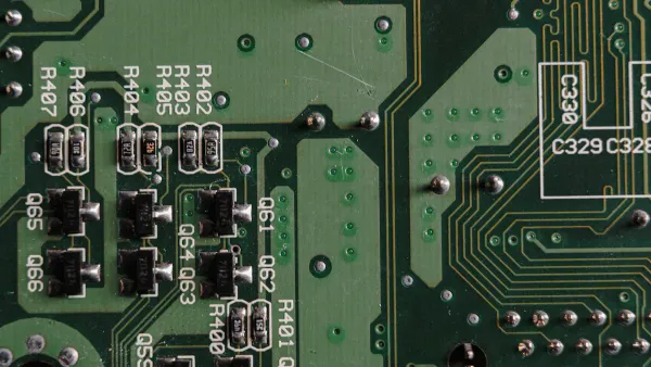
The challenge intensifies with each generation. DDR5 operates at speeds up to 6400 MT/s, and DDR6 will be even faster. At these frequencies, the physical traces on the printed circuit board (PCB) act as complex RC networks. Poor signal integrity can lead to data corruption. Engineers must meticulously control timing to prevent errors.
Key considerations for ensuring data stability include:
| Challenge | Engineering Solution |
|---|---|
| Signal Timing | Engineers adjust the physical length of PCB traces. They often use serpentine (snake-like) routes to deliberately add delay, ensuring clock and data signals arrive in perfect sync. |
| Signal Integrity | High data rates increase issues like reflection, crosstalk, and noise. Proper PCB layout and termination schemes are essential to maintain a clean signal. |
| Verification | Designers use Eye Diagrams to visualize signal quality. A wide, open "eye" indicates a healthy signal with low jitter and a low bit error rate. |
For future standards like DDR6, these challenges will become even more extreme.
The problem is signal integrity with high frequencies, low voltage, long traces and sensitive sub-timings for the DIMMs, all of which will only get more challenging with faster memory.
Ultimately, the ability to precisely engineer the timing delays on a memory bus is fundamental to preventing data errors and unlocking the full bandwidth of modern RAM.
Applications in Wireless and IoT Devices
The principles of the RC network extend far beyond wired circuits. They are essential for the function of modern wireless and Internet of Things (IoT) devices. Engineers use these principles for everything from cleaning up signals to saving battery life.
Signal Filtering in 5G and Wi-Fi 7
Wireless technologies like 5G and Wi-Fi 7 must operate in a crowded radio environment. Devices need to separate the correct information from unwanted electrical noise. A simple RC circuit acts as a low-pass filter. It allows low-frequency data signals to pass through. It simultaneously blocks high-frequency noise.
While advanced communication systems use more complex digital filters, the fundamental RC filtering concept remains a cornerstone of radio frequency (RF) design. Ensuring a clean signal is critical for achieving the high speeds and low latency promised by next-generation wireless standards. This helps devices maintain a strong, reliable connection.
Low-Power IoT Wake-Up Timers
Many IoT devices run on batteries for years. They must conserve energy by spending most of their time in a deep sleep mode. In this state, they consume very little power. However, they need a way to wake up periodically to transmit data. An RC circuit provides a simple and low-power solution for this task.
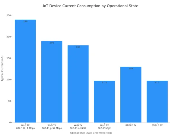
The rc network time constant determines how long the device sleeps. A capacitor slowly charges, and when its voltage reaches a set level, it triggers the device to wake up. This method is extremely efficient. IoT devices in deep sleep can consume mere microamps (µA) of current. In contrast, transmitting data can require hundreds of milliamps (mA).
Challenge: These simple timers face challenges in outdoor environments. Temperature changes affect the resistance and capacitance values, which can make the timer less accurate. Engineers use special compensation techniques to counteract these effects and ensure the timer remains stable across different conditions.
Role in Power and EV Technology

The principles of RC networks are vital in modern power electronics. They are especially important for switch-mode power supplies and the battery systems in electric vehicles (EVs). Engineers use these concepts to improve efficiency, safety, and reliability.
Switch-Mode Power Supplies
Switch-mode power supplies (SMPS) are the heart of most modern electronics, from phone chargers to computer power units. They achieve high efficiency by rapidly switching power on and off. However, this fast switching creates unwanted voltage spikes and electrical noise. These transients can damage sensitive components like MOSFETs.
Engineers use a special RC circuit, called a snubber, to solve this problem. The snubber is placed in parallel with the switching component. It helps to:
- Suppress dangerous voltage spikes.
- Limit how fast the voltage can change (dv/dt).
- Reduce electromagnetic interference (EMI).
- Protect semiconductor devices like SiC MOSFETs.
This protection makes the power supply more reliable. Additionally, designers carefully select RC components for the output filter. The right values smooth the final DC voltage, reducing ripple and ensuring clean power delivery to the load.
Battery Management Systems
A Battery Management System (BMS) is the brain of an EV's battery pack. It ensures the safety and longevity of hundreds or thousands of individual battery cells. One of its key jobs is cell balancing. Some cells may charge or discharge slightly faster than others. A BMS corrects this imbalance.
A simple way to do this is with a passive balancing circuit. Here, a resistor is placed across a fully charged cell to slowly drain a small amount of its energy as heat. The rc network time constant of this circuit determines the rate of discharge. This allows other cells in the pack to catch up, ensuring all cells maintain a similar voltage level.
Innovation on the Horizon 🚀 The future of power electronics is evolving quickly. Researchers are developing systems using wide-bandgap semiconductors like Gallium Nitride (GaN). GaN allows for faster switching and higher efficiency in a smaller package. These advancements are making EV chargers and power systems lighter, more compact, and more robust than ever before.
The RC principle is a foundational concept in electronics. It scales from simple IoT timers to the core of high-performance computing. Engineers continuously work to control its effects. They mitigate unwanted parasitic delays in processors and precisely engineer timing in memory systems. This mastery remains a critical skill for creating the top technologies of 2025.
Looking ahead, researchers are exploring new ways to manage parasitic RC delays:
- Developing novel vertical contact architectures.
- Using 2D van der Waals materials to reduce stack height.
Simultaneously, principles from Reservoir Computing (RC) will help power the next wave of neuromorphic chips, showing the concept's enduring relevance.
FAQ
What is the RC time constant?
The RC time constant (τ = R × C) measures how quickly a capacitor charges or discharges through a resistor. It represents the time needed to charge to 63.2% of the source voltage. This value directly governs a circuit's speed and signal response time.
Why does the RC time constant matter in CPUs?
Tiny wires inside a CPU create unwanted RC delays that slow down signals. Engineers work hard to minimize this effect. Reducing this delay is essential for making processors run at faster clock speeds without introducing data errors.
How do engineers use the RC time constant in IoT devices?
Engineers use RC circuits as simple, low-power timers. The circuit tells a sleeping IoT device when to wake up and send data. This method saves significant battery life. 🔋
This technique allows many battery-powered devices to operate for months or even years on a single charge.
What is a snubber circuit?
A snubber is a protective RC circuit used in power electronics. Its main jobs are to:
- Suppress harmful voltage spikes.
- Reduce electrical noise.
- Protect sensitive parts like transistors.
This simple circuit makes power supplies in chargers and EVs much more reliable.