How to Identify the Symbol Continuity on Electronic Devices
Identify symbol continuity on electronic devices by locating the correct icon for circuit testing, ensuring reliable connections and data quality.
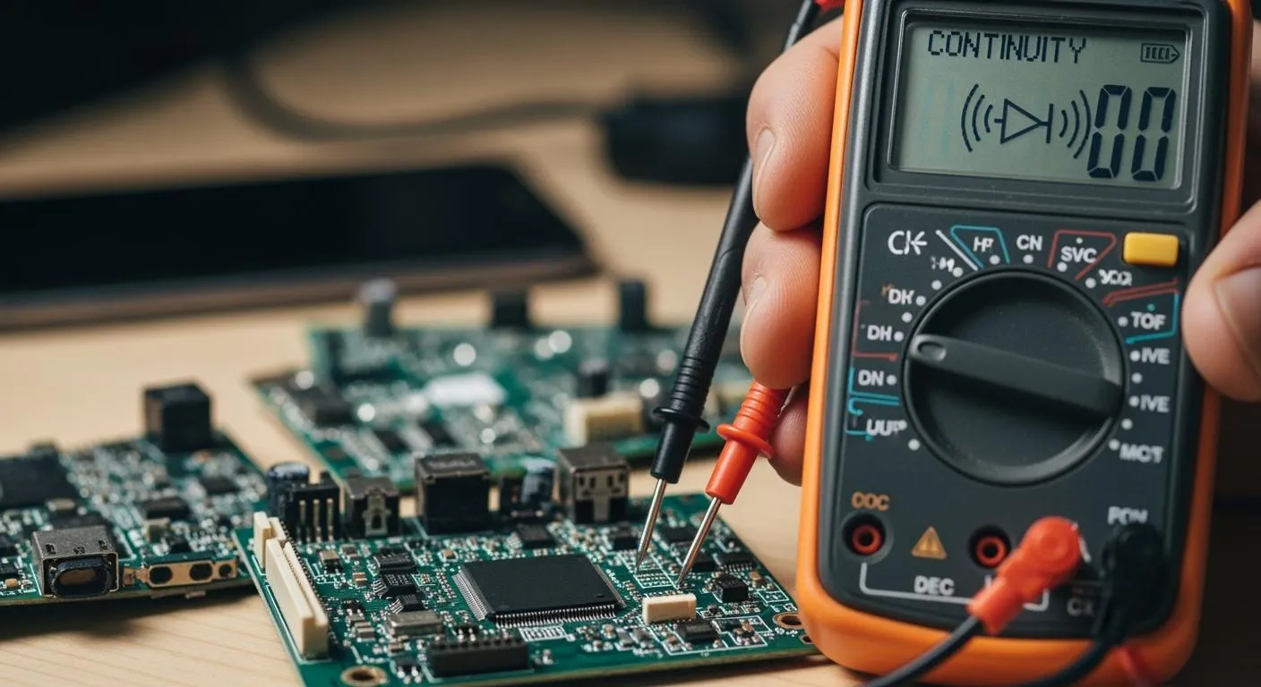
You can identify the symbol continuity on electronic devices by looking for a small icon that often looks like a diode or a series of sound waves. This continuity symbol appears on most digital multimeters and helps you quickly test if a circuit path is complete. Always think about safety before starting: disconnect the device from power and use insulated probes. Recognizing the correct symbol and following safety steps lets you troubleshoot circuits with confidence and improve your data quality.
Key Takeaways
- Look for the continuity symbol, often resembling a diode or sound wave, on your multimeter to test circuit paths effectively.
- Always disconnect power before testing to ensure safety and prevent damage to your devices.
- Use continuity testing to verify connections and maintain data quality, avoiding issues like open circuits that can lead to device malfunctions.
- Recognize different continuity symbols and their meanings to troubleshoot circuits quickly and accurately.
- Follow safety guidelines during testing, such as using insulated probes and checking for damaged wires, to protect yourself and your data.
Continuity Basics
What Is Continuity
You need to understand continuity to ensure reliable circuit operation. Continuity means a complete path exists in a circuit, allowing current to flow without interruption. When you check for continuity, you confirm that wires, resistors, diodes, and other components connect properly. If you find a break, the circuit cannot carry current, and the device will not function. You use the continuity symbol on your testing device to verify these connections.
- Continuity shows that the electrical pathway is intact.
- Discontinuity signals a break or failure in the circuit.
- You rely on continuity testing to maintain data quality and prevent errors.
Why Continuity Matters
You improve data quality by testing continuity in every circuit. If you skip this step, open circuits can cause malfunctioning devices, product recalls, and poor customer experience. You avoid these problems by using the continuity symbol to check each connection.
- Open circuits block current flow and increase resistance.
- Short circuits allow too much current, which can damage components.
- Continuity testing helps you detect faults like broken wires or high-resistance connections.
- You verify soldered connections and assess wiring conditions to ensure data quality.
You protect your data and your devices by making continuity testing part of your routine. You also meet regulatory standards that require a complete, uninterrupted path for current flow.
Continuity in Electronic Devices
You see the continuity symbol on digital multimeters and other testing tools. You use it to check connections on printed circuit boards, cables, and chip-level solutions. In the IC industry, you must ensure every circuit link is functional to maintain data quality.
- Continuity testing is essential for evaluating connections on PCBs.
- You identify faults early, preventing costly recalls and maintaining quality standards.
- Industries like automotive and medical devices depend on reliable circuits for safety and performance.
Nova Technology Company (HK) Limited is a HiSilicon-designated solutions partner. You benefit from their expertise in integrated circuit design, system integration, and chip-level solutions. Their advanced testing methods help you achieve high data quality and reliable electronic applications.
You rely on the continuity symbol to troubleshoot, verify connections, and ensure your data meets industry standards.
Continuity Symbol Identification

Symbol Continuity Designs
You need to recognize the symbol continuity on electronic devices to ensure accurate circuit testing and maintain data quality. The continuity symbol appears in several designs, each helping you identify the correct mode for checking circuit paths. You often see these designs on digital multimeters and other testing tools.
- The continuity symbol usually looks like a sound wave or a diode.
- Arcs or wave-like lines represent the continuity symbol, showing a closed circuit path.
- You use these symbols to verify that wires and connections are intact, which improves data quality.
You must understand these designs because quick identification saves time during troubleshooting. You avoid mistakes and ensure your data remains reliable. You also prevent errors in circuit analysis, which protects your devices and maintains high data quality.
Diode and Sound Wave Symbols
You see two main types of continuity symbols on electronic devices. Each symbol helps you test circuit paths and maintain data quality.
- The sound wave symbol, often shown as three curved lines, indicates the audible beep you hear when continuity exists.
- The diode symbol, sometimes combined with the sound wave, shows that the device can test both continuity and diodes in one mode.
| Symbol Type | Description |
|---|---|
| Sound Wave / Speaker Symbol ))) | Represents the audible beep emitted when continuity is detected. Visually simulates sound waves. |
| Diode + Sound Wave Symbol | Indicates that the multimeter can test both continuity and diodes in a single mode. |
You rely on these symbols to check circuit paths quickly. You improve data quality by confirming that each connection works as intended. You also avoid confusion by knowing what each symbol means, which helps you troubleshoot faster and more accurately.
Where to Find the Continuity Symbol
You find the continuity symbol in several places on electronic devices. You need to know where to look so you can test circuit paths and maintain data quality.
- The continuity symbol appears on the dial or display of digital multimeters.
- You see it near the test mode selector, often grouped with resistance and diode symbols.
- You also find the continuity symbol in user manuals and device documentation.
You must recognize visual cues to identify the continuity symbol among other icons. You look for wave-like lines or a diode shape. You avoid confusion by checking the device's legend or guide.
| Feature | Digital Multimeter | Analog Multimeter |
|---|---|---|
| Continuity Indication | Shows a symbol or numerical value; near-zero resistance indicates continuity | Needle deflects toward zero resistance to indicate continuity |
| Audible Indication | Provides an audible beep when continuity is detected; displays 'OL' for open circuit | No audible indication; relies on needle movement |
| Continuity Symbols | Commonly uses sound wave symbol ())) for continuity testing | Typically does not have a specific symbol for continuity testing |
You improve data quality by using the correct continuity symbol. You avoid errors in circuit testing and ensure your data remains consistent. You also meet industry standards for electronic symbols, which helps you maintain high-quality results.
| Standard | Description |
|---|---|
| IEC 60617:2025 | Current international standard for electronic symbols. |
| IEEE 315-1975 | Reaffirmed in 1993, inactivated without replacement as of November 7, 2019. |
| IEEE 91/91a | Graphic symbols for logic functions, referenced in IEEE 315 / ANSI Y32.2. |
| Australian Standard AS 1102 | Based on IEC 60617, withdrawn without replacement. |
| DIN 40700 and 40900 | Inactivated standards in Germany. |
| JIC symbols | Approved by the NMTBA, extracted from NMTBA Specification EGPl-1967. |
| IEC 61131-3:2025 | Standards for ladder-logic symbols. |
Tip: You always check the continuity symbol before testing a circuit. You improve data quality and avoid mistakes by using the correct mode. You also protect your devices and ensure your data meets industry standards.
You use the continuity symbol to troubleshoot circuits, verify connections, and maintain high data quality. You rely on accurate data to make decisions and keep your electronic devices working properly.
Continuity Testing Steps

Setting Up for Continuity Testing
You start continuity testing by preparing your multimeter and ensuring data quality. First, disconnect power from the circuit to protect yourself and your devices. Insert the black test lead into the COM jack. Place the red lead into the VΩ jack. Select the symbol continuity mode on your multimeter. Connect the test leads across the component or electrical connections you want to check. The multimeter emits a beep if continuity exists. No beep means the circuit is open. Turn off the multimeter after testing. These steps help you maintain data quality and prevent errors in your testing process.
Tip: Always disconnect power before continuity testing. This simple step improves safety and protects your data.
Interpreting Continuity Results
You interpret continuity testing results by checking resistance values and listening for the beep. Good continuity means low resistance and a closed circuit. Questionable connections show slightly higher resistance. Bad connections or open circuits display high resistance or no beep. Compare your results with previous data or similar circuits to ensure data quality. Use the table below to guide your interpretation:
| Test results | Conclusion | Further investigation |
|---|---|---|
| Rt < 0.1 Ω | Good connection | Not required |
| 0.1 Ω < Rt < 1 Ω | Questionable connection | Only if necessary |
| Rt > 1 Ω | Bad connection | Required |
| Open connection | Open connection | Required |
Significant deviations from expected resistance values indicate possible faults. Investigate further to maintain high data quality and reliable electrical connections.
Safety Tips for Continuity Testing
You protect yourself and your data by following safety guidelines during continuity testing. Use proper wiring and connectors. Test GFCIs monthly using the test button. Check switches and insulation for damage. Never use a three-prong grounding plug with the third prong broken off. Use extension cords with enough ampacity and intact insulation. Inspect cords regularly. Disconnect cords by the plug, not by pulling on the cord. Use correct connectors for your current and voltage needs. Test circuits to ensure they are de-energized before working. Work with a buddy trained in CPR and emergency procedures. Lock out and tag out circuits and equipment before starting. Remove jewelry and metal objects before testing.
Note: Following these safety tips ensures your continuity testing process protects both you and your data quality.
You improve data quality and circuit reliability by using your multimeter correctly, interpreting results accurately, and following safety steps. Continuity testing helps you detect faults, verify connections, and maintain high standards in your electronic work.
Troubleshooting and Data Quality
Common Continuity Symbol Mistakes
You often make mistakes during continuity testing that affect data quality. You must avoid these errors to ensure accurate circuit analysis and reliable electrical connections. The table below shows frequent mistakes and their explanations:
| Mistake | Explanation |
|---|---|
| Testing live circuits | Continuity testing must be done on de-energized circuits to avoid damage and inaccurate readings. |
| Misinterpreting weak beeps | A faint beep may indicate a loose connection; users often misinterpret this as a continuous path. |
| Using the wrong mode | Selecting the wrong mode can lead to misleading readings; continuity mode must be chosen for checks. |
| Poor probe contact | Dirty or loose probes can prevent proper connection, leading to false "no continuity" readings. |
| Ignoring meter threshold | Users may not realize that a circuit with higher resistance may not trigger the buzzer, affecting results. |
You improve data quality by checking your multimeter settings, cleaning probes, and ensuring circuits are powered off before testing. You also listen carefully for strong beeps and check resistance values to confirm connections.
Improving Data Quality with Continuity Testing
You boost data quality by using continuity testing throughout your workflow. You confirm that electrical pathways remain connected and capable of carrying current between designated points. You identify damaged traces, broken interconnects, failed solder joints, and disconnected pathways. You use continuity testing during manufacturing, inspection, maintenance, and failure analysis. You verify circuit integrity and locate electrical faults. You compare resistance readings and listen for the multimeter beep to ensure connections work as intended. You rely on continuity testing to troubleshoot electrical faults and maintain high standards for your data.
Tip: You always use continuity testing to check connections before powering up new circuits. This step prevents component damage and saves time.
Practical Applications
You apply continuity testing in many scenarios to maintain data quality and troubleshoot circuits. The tables below show common applications:
| Application Type | Description |
|---|---|
| Checking Wiring | Technicians use continuity testers to check for breaks or faults in electrical wiring. |
| Fuse Testing | Used to determine whether a fuse is blown. |
| Switch Functionality | Checks if switches are functioning correctly. |
| Application Type | Description |
|---|---|
| Safety Checks | Routine continuity checks on fuses, cables, and connectors prevent electrical hazards. |
| Troubleshooting | Helps locate short circuits and unintended connections in circuit boards and electrical systems. |
| Preventive Testing | Verifying connections before powering new circuits prevents component damage and saves time. |
You use continuity testing to check wiring, test fuses, and verify switch functionality. You perform safety checks and preventive testing to protect your data and devices. You troubleshoot circuits and maintain reliable electrical connections.
Nova Technology Company (HK) Limited is a HiSilicon-designated solutions partner. You benefit from their expertise in chip-level solutions, system integration, and advanced testing methods. Their professional approach supports the IC industry and helps you achieve high data quality in semiconductor applications.
You rely on continuity testing, the symbol continuity, and your multimeter to maintain data quality, troubleshoot electrical faults, and ensure reliable connections in every circuit.
You now recognize the continuity symbol and understand how to use it for circuit testing. Continuity testing helps you detect breaks in circuits, ensuring all components connect and operate correctly. This process maintains the integrity of electronic systems and improves data quality.
You build confidence and protect your devices by following safety steps during every test.
Explore these training resources to strengthen your skills:
- A Guide to Continuity Testing with a Multimeter
- Training Courses
- Digital Multimeter Basics Course
- Webinars
- Resources for Educators and Students
You apply these skills to troubleshoot circuits, maintain data quality, and work safely with electronic devices.
FAQ
What does the continuity symbol look like on a multimeter?
You see the continuity symbol as a sound wave or diode icon. You select continuity mode by turning the dial to this symbol. This helps you start continuity testing and check circuit connections for accuracy and consistency.
How do you use continuity mode for testing circuits?
You disconnect power, set your multimeter to continuity mode, and place probes across circuit connections. You listen for a beep or check resistance. This process improves data quality assessment and helps you detect open circuits.
Why is continuity testing important for data quality?
You rely on continuity testing to verify connections and maintain accuracy. This testing prevents data quality issues by ensuring consistency in circuit paths. You use it as part of your data quality framework and data quality evaluation.
Can you use resistance mode instead of continuity mode?
You can use resistance mode, but continuity mode gives faster results. You check resistance values for accuracy and consistency. Continuity mode provides an audible signal, making testing easier and improving data quality analysis.
What safety steps should you follow during continuity testing?
You ensure safety by disconnecting power before testing. You use insulated probes and check for damaged wires. You follow these steps to protect data and electrical connections, maintaining accuracy and consistency in your testing circuits.