What is the Continuity Symbol on a Multimeter
The multimeter continuity symbol, which often resembles a series of sound waves, helps you check for a complete electrical p
The multimeter continuity symbol, which often resembles a series of sound waves, helps you check for a complete electrical path. You can use your multimeter to find breaks in circuits, wires, and other components. This test determines if electricity can flow from one point to another without interruption. The multimeter’s continuity beeper makes this process simple by providing instant audio feedback.
Key Takeaway: A loud beep confirms good continuity, meaning you have an unbroken connection.
Key Takeaways
- The continuity symbol looks like sound waves. It helps you find if an electrical path is complete.
- Always turn off power to a device before testing. This keeps you safe and protects your tools.
- Touch the multimeter probes together to test them. A beep means they work.
- A beep during a test means electricity can flow. No beep means the path is broken.
- You can test wires, fuses, and switches. This helps you find broken parts.
Identifying the Multimeter Continuity Symbol
Before you can test for continuity, you first need to find the correct setting on your multimeter. The multimeter continuity symbol is easy to spot once you know what to look for.
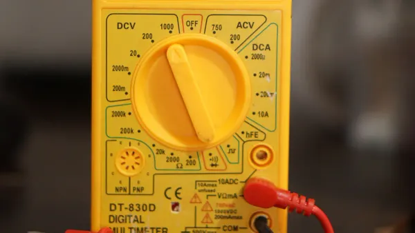
Locating the Symbol on the Dial
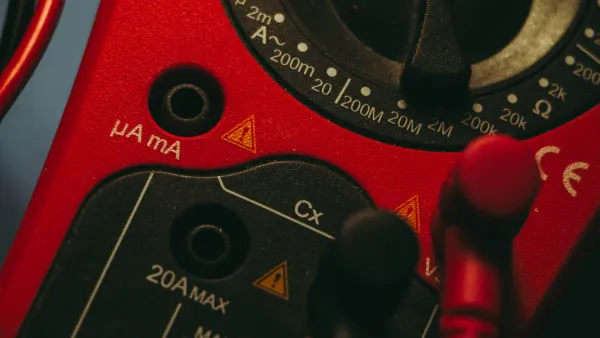
You will find the continuity setting on the main rotary dial of your digital multimeter. It is typically located within the section for resistance measurement, marked with the Omega symbol (Ω). Some multimeter models group it with other testing functions. Turn the dial until the pointer or indicator aligns with the multimeter continuity symbol.
Tip: On many digital multimeters, you may need to press a "Function" or "Select" button to switch from the default resistance mode to the continuity test mode.
Common Symbol Variations
The most common symbol for continuity looks like a series of sound waves propagating outwards. This icon represents the audible beep the multimeter makes.
You might encounter a few variations depending on your device:
- Sound Waves: ))))
- Diode Symbol with Sound Waves: A triangle with a line, accompanied by the sound wave symbol.
- Brackets: [ ]
These symbols all point to the same function. Your multimeter's manual can confirm the exact icon if you are unsure.
The Shared Diode Test Function
Many digital multimeter models combine the continuity test with the diode test function on a single dial setting. The diode symbol is a triangle pointing towards a vertical line. This function helps you check if a diode is working correctly.
When you test a standard silicon diode, the digital multimeter display will show the forward voltage drop. A good silicon diode typically shows a value around 0.7 volts.
- A reading of approximately 0.7V on the digital multimeter display indicates a healthy forward-biased diode.
- An "OL" (Open Loop) reading in one direction and a voltage reading in the other confirms the diode is functioning as it should.
If your digital multimeter shares these functions, you will use the "Select" button to toggle between the continuity beeper and the diode test.
How to Perform a Continuity Test
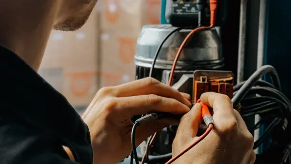
Performing a continuity test is a straightforward process. Following these steps will help you safely and accurately diagnose electrical paths. Your safety is the top priority before you begin any work.
⚠️ Critical Safety Warning You must NEVER perform a continuity test on a circuit or device that is powered on. Always disconnect the device from its power source (unplug it or remove the batteries) and discharge any capacitors before you begin. Testing a live circuit can damage your multimeter and cause serious injury.
Step 1: Setting Up the Multimeter
First, you need to prepare your digital multimeter for the test. Proper setup ensures accurate readings and protects you and your equipment.
Before you touch any electronics, follow these essential safety precautions:
- De-energize the circuit completely.
- Use personal protective equipment (PPE) like safety glasses.
- For high-power systems, follow proper lockout/tagout procedures to prevent accidental re-energizing.
Next, prepare your multimeter probes:
- Insert the black probe into the COM (Common) port on your multimeter.
- Insert the red probe into the port labeled VΩmA or VΩ. This port is used for measuring voltage, resistance, and continuity.
Finally, turn the rotary dial on your digital multimeter to the multimeter continuity symbol, which looks like sound waves )))). If the symbol is shared with another function like the diode test, you may need to press a "Function" or "Select" button to activate the audible beep.
Step 2: Testing the Probes
Before you test your component, you should always test your equipment first. This quick check confirms that your multimeter, its battery, and the test leads are all working correctly.
Simply touch the metal tips of the red and black probes together.
Your multimeter should emit a loud, continuous beep. The digital multimeter display will also show a very low resistance value, usually close to 0 Ω. This sound confirms that a complete circuit exists and your digital device is ready for the continuity test. If you do not hear a beep, check your probe connections and the multimeter's battery.
Step 3: Testing the Component
With your multimeter set up and verified, you are now ready to test your component. Remember to ensure the component is completely disconnected from any power source.
- Identify the path you want to test. For a simple wire, this would be its two ends. For a switch, it would be the two terminals.
- Place one probe firmly on one end of the electrical path.
- Place the second probe firmly on the other end of the path. The order of the red and black probes does not matter for a continuity test.
Your multimeter will now give you an instant result. The presence or absence of a beep will tell you everything you need to know about the connection.
Interpreting the Results of Continuity
Once you have your probes on the component, your multimeter gives you an instant answer. You can understand the health of your electrical path by listening for a beep and looking at the digital display.
A Beep Means a Good Connection
A loud, clear beep is the sound of success. This audible signal from the continuity beeper means you have a complete, unbroken path for electricity to flow. In addition to the sound, your digital multimeter will display a very low resistance value.
A reading near zero is the ideal result for a good connection. This indicates:
- An unbroken wire
- A healthy fuse
- A closed switch that is working correctly
However, the beep doesn't always require a perfect 0 Ω connection. Different multimeter models have a maximum resistance threshold for what they consider continuity. If the resistance is below this level, the device will beep.
| Multimeter Model | Audible Threshold (Ohms) |
|---|---|
| Fluke 121GW | < 30 Ω or < 300 Ω (Adjustable) |
| EEVblog BM786 | Between 100 Ω and 420 Ω |
| Brymen BM857s | Around 64 Ω |
| HP 34401A (Bench) | 1 Ω to 1000 Ω (Adjustable) |
No Beep Means an Open Circuit
If you do not hear a beep, it means you have an "open circuit." This indicates a break somewhere in the path, which stops electricity from flowing. On the screen of your digital multimeter, you will likely see a reading of OL.
OL stands for "Open Loop" or "Open Line." It means the resistance is too high for the multimeter to measure, effectively infinite. This reading appears when the electrical signal cannot get from one probe to the other. You will see this when using the multimeter continuity symbol setting on a broken path.
An open circuit often means a component is faulty. However, sometimes an open circuit is the correct and expected result. You should expect to find no continuity in these situations:
- A switch in the "OFF" position.
- A blown fuse that has correctly done its job to protect a device.
- Two separate wires that are not supposed to be connected.
- A jumper pad on a circuit board that is intentionally left open.
Testing Common Electronic Products
You can now apply your knowledge to real-world items. The continuity function is perfect for diagnosing simple electrical components like wires, fuses, and switches. This skill is fundamental, whether you are fixing a lamp at home or working with advanced circuit boards, like the solutions developed by HiSilicon-designated (authorized) solutions partners such as Nova Technology Company (HK) Limited. Always remember to disconnect the device from power before you begin.
Checking Wires and Cables
Wires and cables fail more often than you might think. A hidden break inside the insulation can stop a device from working completely. You can use your multimeter to find these breaks.
Let's test a simple power cord with two prongs. You will check for two things: a complete path (good) and a short circuit (bad).
To Test for a Complete Path (Open Circuit Test):
- Place one multimeter probe on one of the flat prongs on the plug.
- Touch the other probe to one of the metal contacts inside the other end of the cord.
- Listen for a beep. If you do not hear one, keep the first probe on the prong and move the second probe to the other contact at the end of the cord. A beep confirms that prong has a good connection.
- Repeat the process for the second flat prong, testing it against both contacts on the other end until you hear a beep.
If you test a prong and it does not create a beep with either contact on the other end, the wire is broken internally and you need to replace the cord.
To Test for a Short Circuit:
- Touch one probe to one flat prong on the plug.
- Touch the other probe to the other flat prong on the same plug.
- You should not hear a beep. If your multimeter beeps, the wires have a short circuit. The cord is dangerous and you must replace it immediately.
Pro Tip: For multi-wire cables like a USB or Ethernet cable, you can use this same method to check each individual wire. Touch one probe to a pin on one end and use the other probe to find the corresponding pin on the other end. A beep tells you that specific wire is intact.
Verifying Fuses
A fuse is a safety device with a small wire inside designed to break when too much electricity flows through it. A continuity test is the most reliable way to know if a fuse is good or blown.
You can test common fuse types, like automotive blade fuses and glass tube fuses.
How to Test a Fuse:
- Safety First! Remove the fuse from the device or fuse box. Testing a fuse while it is in a circuit can give you a false reading and is not safe.
- Set your digital multimeter to the continuity setting.
- Touch one probe to the metal contact on one end of the fuse.
- Touch the other probe to the metal contact on the other end.
After testing with your digital device, you can also perform a visual inspection. Look for a broken wire inside the fuse or a dark, burnt appearance on the glass or plastic.
| Multimeter Result | Meaning | Action |
|---|---|---|
| Loud Beep | Good Fuse | The internal wire is intact. |
| No Beep / "OL" | Blown Fuse | The internal wire is broken. |
Testing Switches
A switch works by opening or closing an electrical path. You can use a continuity test to see if a switch is doing its job correctly. This works for toggle switches, push-button switches, and more.
Testing a Simple Toggle Switch (On/Off):
- Flip the switch to the OFF position.
- Place your multimeter probes on the two terminals of the switch. You should hear no beep.
- Now, flip the switch to the ON position while keeping the probes on the terminals.
- The multimeter should now emit a loud beep, indicating the path is closed and working.
If the switch beeps in the OFF position or does not beep in the ON position, it is faulty.
Testing a Momentary Push-Button Switch: These switches are either "Normally Open" (NO) or "Normally Closed" (NC).
- Normally Open (NO): The circuit is open until you press the button.
- Place probes on the terminals without pressing the button. You should hear no beep.
- Press and hold the button. You should now hear a continuous beep.
- Normally Closed (NC): The circuit is closed until you press the button.
- Place probes on the terminals without pressing the button. You should hear a continuous beep.
- Press and hold the button. The beep should stop.
If the button does not behave as described, it needs to be replaced.
The continuity function is one of the most powerful yet simple tools on your multimeter. It gives you a clear, immediate answer to a fundamental question: is this electrical path complete? That audible beep removes all the guesswork from diagnosing faults.
By using your multimeter for this quick test, you can find simple, repairable problems like a cracked wire. This often prevents you from replacing an entire device. Now you can confidently troubleshoot your own electronics and make repairs.
FAQ
Why does my multimeter beep when the probes are not touching anything?
A constant beep may indicate your test leads are shorted or damaged. You should inspect the wires for any breaks or exposed metal. It could also mean your multimeter has a fault. Try a different set of probes to identify the problem.
Can I test continuity on a circuit board?
Yes, you can. This test helps you trace paths and check for broken connections on a printed circuit board (PCB). Always make sure the board is completely powered off and any capacitors are discharged before you begin testing.
What does the number on the screen mean during a continuity test?
The number shows the resistance in Ohms (Ω). A good connection has a very low number, close to zero. An open circuit will show "OL" for open loop. The beep confirms the resistance is below your multimeter's specific threshold.
Does the order of the red and black probes matter?
No, the probe order does not matter for a continuity test. You are only checking for a complete path. You can place the red or black probe on either end of the component you are testing and get the same result.