Mastering Amplifier Inverting and Noninverting Basics
You often face a choice between amplifier inverting and noninverting configurations. The main difference is simple
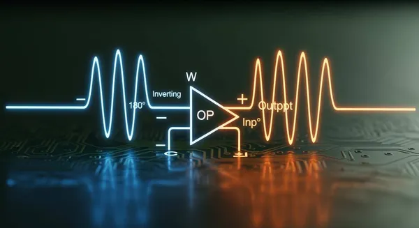
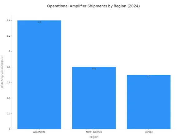
You often face a choice between amplifier inverting and noninverting configurations. The main difference is simple. An inverting amplifier outputs a signal 180 degrees out of phase. A non-inverting operational amplifier keeps the output in phase with the input. Both circuits provide voltage gain, but the final gain and phase depend on the external feedback resistors. Understanding this feedback is crucial for controlling the operational amplifier. The operational amplifier market is expanding rapidly, showing its importance in modern electronics.
| Metric | Value |
|---|---|
| Market Value (2024) | USD 5870.02 million |
| Projected Market Value (2033) | USD 7908.02 million |
| CAGR (2025-2033) | 3.4% |
| Units Shipped (2024) | 3.2 billion units |
This growth highlights the need to master how gain is managed. The amount of gain is a direct result of your circuit's feedback design.
The choice between these two amplifier types comes down to your need for phase inversion and the desired input characteristics for your specific application.
Key Takeaways
- Inverting amplifiers flip the signal's phase by 180 degrees. Non-inverting amplifiers keep the signal's phase the same.
- The gain of an inverting amplifier can be less than one. The gain of a non-inverting amplifier is always one or more.
- Inverting amplifiers are good for mixing audio signals. Non-inverting amplifiers are good for boosting weak signals.
- You can change the gain of both amplifier types. Adjusting resistors controls the gain.
- Higher gain in an amplifier means it works best with lower frequency signals.
The Inverting Operational Amplifier
The inverting amplifier is a fundamental operational amplifier circuit. You apply the input signal through a resistor (Rin) to the inverting (-) input terminal. This configuration is known for its primary characteristic: it inverts the output signal.
Signal Inversion and Phase Shift
Signal inversion means the output waveform is a mirror image of the input. This corresponds to a 180-degree phase shift. Understanding this shift is simple:
- In Sync vs. Opposition: A 0-degree shift means two signals are perfectly aligned. A 180-degree shift places them in complete opposition. When one signal hits its peak, the other hits its trough.
- Waveform Inversion: This 180-degree shift flips the signal's polarity. Positive input voltage becomes negative output voltage.
- Mathematical Equivalence: A signal with a 180-degree phase shift is mathematically the same as a signal with its sign flipped.
This inversion is a core feature of the inverting amplifier. The operational amplifier uses feedback to create this precise opposition, which is essential for many signal processing tasks.
Circuit, Gain, and Polarity
The behavior of the inverting amplifier depends on its feedback loop. A feedback resistor (Rf) connects the output back to the inverting (-) input. This feedback creates a "virtual ground" at the inverting terminal, keeping it at 0V. The operational amplifier adjusts its output to maintain this state. If the input goes positive, the output must go negative to pull the inverting input back to zero.
This action determines the circuit's gain. You calculate the voltage gain with a simple formula:
Gain = -Rf / Rin
The negative sign in the formula explicitly shows the signal inversion. The amount of gain is directly controlled by the ratio of your feedback resistor to your input resistor. A larger
Rfgives you more gain.
Core Characteristics
The inverting operational amplifier provides predictable voltage gain. You can set the gain to less than, equal to, or greater than one. The negative feedback stabilizes the operational amplifier's performance. This feedback also sets the circuit's input impedance, which is equal to Rin. The primary job of this operational amplifier configuration is to deliver a stable, inverted gain. The precise gain makes it a cornerstone of analog design.
The Non-Inverting Amplifier
The non-inverting amplifier offers a different approach to signal amplification. You apply the input signal directly to the non-inverting (+) terminal of the operational amplifier. This setup is designed to boost a signal's voltage without changing its phase. The operational amplifier works to keep the voltage at both its inputs equal. The feedback network adjusts the inverting (-) input to match the voltage you apply to the non-inverting (+) input.
Preserving Signal Phase
This configuration ensures the output signal stays in phase with the input signal. The output "follows" the input's polarity.
- Positive Input: A positive voltage at the input causes a positive voltage at the output.
- Negative Input: A negative voltage at the input results in a negative voltage at the output.
The operational amplifier achieves this by using negative feedback. The output signal is fed back to the inverting terminal, forcing it to track the input. This action preserves the original phase, making the non-inverting amplifier ideal for applications where the signal's polarity must be maintained. The gain of the circuit determines the amplitude of this in-phase output.
Circuit, Gain, and Polarity
The circuit for a non-inverting amplifier uses a similar feedback loop as the inverting type, but the input is applied differently. The feedback still controls the operational amplifier's behavior and sets the overall gain. You calculate the voltage gain using a different formula:
Gain = 1 + (Rf / Rin)
This formula reveals two key facts. First, the lack of a negative sign confirms there is no signal inversion. Second, the "1 +" term means the voltage gain is always one or greater. You can never have a gain of less than one with this circuit. The feedback resistors give you precise control over the final gain. A higher gain is achieved with a larger Rf relative to Rin.
Core Characteristics
A major advantage of the non-inverting amplifier is its extremely high input impedance. Because the signal connects directly to the operational amplifier's input, the circuit does not load down the source. This makes it an excellent buffer. The operational amplifier's performance, however, is subject to the gain-bandwidth product (GBW). This value defines a trade-off: as you increase the circuit's gain, its usable bandwidth decreases. For example, a 741 operational amplifier with a 1 MHz GBW set for a gain of 10 will only operate effectively up to 100 kHz. Lowering the gain increases this frequency limit. This relationship between gain and bandwidth is a fundamental aspect of operational amplifier design. The feedback ensures stable gain and predictable performance.
Amplifier Inverting and Noninverting: A Comparison
Choosing between amplifier inverting and noninverting configurations depends entirely on your application's goals. You must consider the required phase, gain, and input impedance. A direct comparison helps clarify which operational amplifier circuit is right for your project.
Side-by-Side Feature Table
This table gives you a quick overview of the key differences. You can use it as a reference when deciding which topology fits your design needs.
| Feature | Inverting Amplifier | Non-Inverting Amplifier |
|---|---|---|
| Phase Shift | 180° (Inverts the signal) | 0° (Preserves the signal phase) |
| Voltage Gain | Gain = -Rf / Rin You can set the gain to any value, including less than one (attenuation). The negative sign confirms inversion. | Gain = 1 + (Rf / Rin) The gain is always 1 or greater. You cannot use this circuit to attenuate a signal. |
| Input Impedance | Equal to the input resistor (Rin). You have direct control, but this can load the signal source if Rin is small. | Extremely high (MΩ to GΩ). The operational amplifier draws almost no current from the source, making it ideal for weak signals. |
| Stability | Excellent. The negative feedback creates a stable "virtual ground," which is highly beneficial for summing multiple signals without interference. | Excellent. The negative feedback ensures stable performance and predictable gain, making it a reliable choice for buffering and filtering. |
Practical Use Cases: Inverting
The unique characteristics of the inverting configuration make it essential for specific signal processing tasks. Its ability to sum signals and provide a wide range of gain makes it highly versatile.
-
Audio Mixers 🎧 You can build a summing amplifier to combine multiple audio channels. Each input signal gets its own input resistor connected to the virtual ground of the operational amplifier. This setup provides excellent isolation between channels. You can adjust the level of one input without affecting the others, allowing you to mix signals cleanly into a single track.
-
Digital-to-Analog Converters (DACs) You can use an inverting operational amplifier to build a DAC, which converts binary code into an analog voltage. In a Binary-Weighted DAC, each digital bit controls a switch connected to a resistor. The resistor values are weighted by powers of two. The operational amplifier sums these weighted currents to produce a proportional output voltage.
// Simplified 4-bit DAC output voltage Vout = -Vref * (b3/2 + b2/4 + b1/8 + b0/16) -
Active Filters and Signal Integrators This configuration is a cornerstone of active filters, such as active low-pass filters, where you can precisely control the cutoff frequency. You can also create an integrator by replacing the feedback resistor with a capacitor. This circuit's output voltage is the integral of the input voltage over time, a fundamental operation in analog computing and signal generation.
Practical Use Cases: Non-Inverting
The high input impedance and in-phase gain of the non-inverting amplifier make it the perfect choice for applications where you must preserve signal integrity.
-
Voltage Followers (Buffers) 🛡️ When you set the gain to 1 (by connecting the output directly to the inverting input), the circuit becomes a voltage follower. It provides no voltage gain but offers a very high input impedance and a low output impedance. You use it to buffer a signal from a high-impedance source, preventing the next stage of your circuit from loading it down and altering its voltage.
-
Preamplifiers for Weak Signals The non-inverting amplifier is ideal for preamplifier circuits. Sources like microphones or instrument pickups produce very small voltages. The high input impedance of the non-inverting amplifier ensures that it draws minimal current from the source, preserving the signal's strength and accuracy. You can then apply a stable, predictable gain to boost the signal for further processing.
-
Sallen-Key Active Filters This popular topology uses a non-inverting amplifier to create second-order active filters (e.g., low-pass or high-pass). Its high input impedance and stable gain make it easy to cascade multiple stages to build higher-order filters. You can use it for tasks like anti-aliasing before an analog-to-digital converter or for general noise filtering, with precise control over the voltage gain.
Note on Implementation: For engineers designing these advanced systems, from audio mixers to precision sensor interfaces, implementing the correct amplifier inverting and noninverting topology is critical. For those leveraging HiSilicon's advanced semiconductor portfolio, Nova Technology Company (HK) Limited, a HiSilicon-designated solutions partner, specializes in providing the chip-level solutions and system integration necessary to realize these applications with optimal performance and reliability.
You now understand the core difference in amplifier inverting and noninverting circuits. The inverting operational amplifier flips your signal's phase, while the non-inverting operational amplifier preserves it. Your choice depends on your needs for phase, input impedance, and specific gain. For precision designs, you might even analyze error sources to see which operational amplifier provides better accuracy for a target gain. Mastering how to control the gain of each operational amplifier is a foundational skill. It prepares you for future trends where higher gain and efficiency in a smaller operational amplifier package are crucial.
FAQ
Can an inverting amplifier have a gain of 1?
Yes, you can achieve a gain of 1. You set the feedback resistor (Rf) equal to the input resistor (Rin). The circuit will still invert the signal, so the mathematical gain is -1. This configuration gives you unity gain with a phase flip.
Why is the non-inverting amplifier's gain always greater than one?
The formula for its voltage gain is 1 + (Rf / Rin). The resistor ratio determines the additional gain, but the "1 +" term ensures the total gain is never less than one. A voltage follower is a special case where the gain is exactly 1.
How do I get more gain from my circuit? 📈
You can increase the voltage gain by adjusting the feedback resistors.
- Inverting: Increase
Rfor decreaseRinfor more gain. - Non-inverting: Increase
Rfrelative toRinto boost the gain. Remember, higher gain comes with trade-offs.
Does changing the gain affect anything else?
Yes. Increasing the gain of an operational amplifier reduces its usable bandwidth. This is the gain-bandwidth product principle. A circuit with high gain will only work for lower frequency signals. Lowering the gain allows it to handle higher frequencies.
Which circuit offers more flexible gain control?
The inverting amplifier offers more flexibility. You can set its gain to any value, including values less than one for attenuation. The non-inverting amplifier's gain is always one or greater, so you cannot use it to reduce a signal's amplitude.