Future Trends and Applications of the LBC817-40LT1G in Electronics Design
Future Trends and Applications of the [sku:LBC817-40LT1G] in Electronics Design table { border: 1px solid #000; border-collapse: collapse; width: 100%;
Introduction
In the rapidly evolving landscape of electronics design, the LBC817-40LT1G is gaining prominence as a versatile NPN transistor. As the demand for efficient and compact components grows, understanding the specifications and applications of such components becomes crucial. The semiconductor industry has seen significant growth, with global revenues reaching $595.2 billion in 2026, showcasing the increasing reliance on advanced electronic components. The LBC817-40LT1G plays a pivotal role in various applications, from consumer electronics to industrial systems, making it an essential component for engineers and designers.
Technical Overview
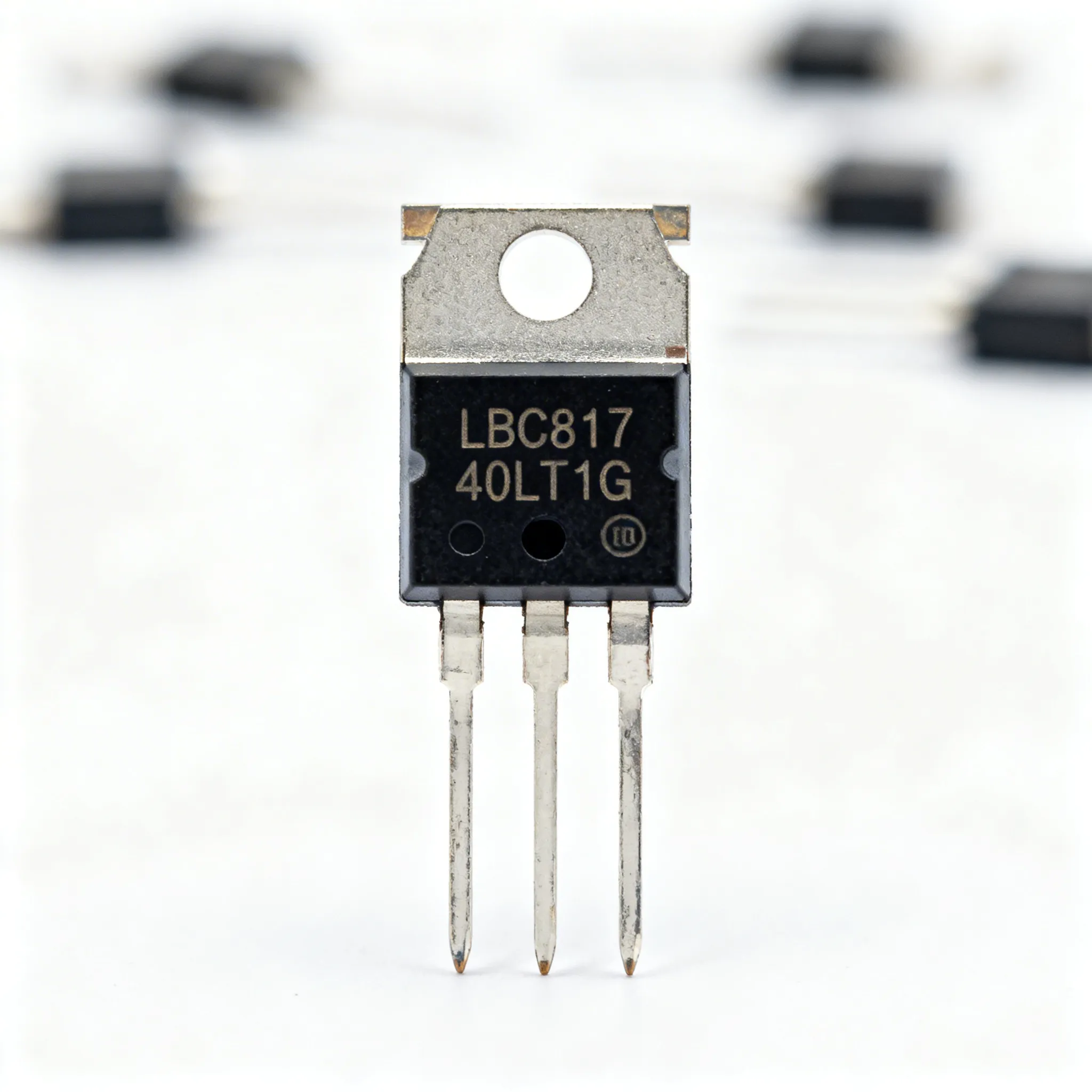
The LBC817-40LT1G is a general-purpose NPN transistor designed for low-power amplification and switching applications. Operating efficiently in a wide range of electronic circuits, it provides a reliable solution for designers seeking balance between performance and cost. The core principle of the LBC817-40LT1G lies in its ability to amplify current, making it suitable for circuits requiring signal amplification or switching tasks.
This transistor is characterized by its high gain and low saturation voltage, which are critical for minimizing power loss and enhancing efficiency. It is typically housed in a small SOT-23 package, which makes it ideal for compact designs where space is a constraint. The LBC817-40LT1G is compatible with automated assembly processes, ensuring ease of integration into modern electronics manufacturing.
Detailed Specifications
Understanding the specific electrical, thermal, and mechanical properties of the LBC817-40LT1G is essential for its effective use in design. Below are detailed tables outlining these specifications:
| Parameter | Value | Units | Notes |
|---|---|---|---|
| Collector-Emitter Voltage (VCEO) | 45 | V | Maximum voltage across collector and emitter |
| Collector-Base Voltage (VCBO) | 50 | V | Maximum voltage across collector and base |
| Emitter-Base Voltage (VEBO) | 6 | V | Maximum voltage across emitter and base |
| Collector Current (IC) | 0.5 | A | Maximum continuous current |
| Base Current (IB) | 0.1 | A | Maximum base current |
| DC Current Gain (hFE) | 250 | Measured at IC = 10mA, VCE = 5V | |
| Collector-Emitter Saturation Voltage (VCE(sat)) | 0.7 | V | Typical value at IC = 500mA, IB = 50mA |
| Transition Frequency (fT) | 100 | MHz | Frequency at which gain is 1 |
| Power Dissipation (PD) | 310 | mW | Maximum allowable power dissipation |
| Thermal Resistance (RθJA) | 500 | °C/W | Junction to ambient |
| Parameter | Value | Units | Notes |
|---|---|---|---|
| Package Type | SOT-23 | Standard surface-mount package | |
| Package Dimensions | 2.9 x 1.3 | mm | Length x Width |
| Weight | 0.008 | g | Typical unit weight |
| Thermal Resistance, Junction to Ambient (RθJA) | 500 | °C/W | Effective thermal resistance |
| Operating Temperature Range | -55 to 150 | °C | Ambient temperature range |
| Storage Temperature Range | -65 to 150 | °C | Storage condition range |
| Lead Finish | Matte Tin | Lead-free plating | |
| Moisture Sensitivity Level (MSL) | 1 | Unlimited floor life at ≤30°C/85% RH |
| Application | Advantages | Disadvantages | Notes |
|---|---|---|---|
| Signal Amplification | High gain | Limited power handling | Ideal for low-power audio circuits |
| Switching Circuits | Low saturation voltage | Not suitable for high currents | Efficient for digital logic applications |
| Voltage Regulation | Stable operation | Requires additional components | Used in small regulator circuits |
| Oscillator Circuits | Reliable frequency response | Complex design | Common in RF applications |
| LED Drivers | Compact design | Limited current capacity | Useful for low-power LED arrays |
The tables above provide a comprehensive look at the LBC817-40LT1G's capabilities. Its electrical specifications emphasize its suitability for low-power applications, while its thermal and mechanical properties ensure it can operate reliably in various environments. The application comparison table highlights its versatility across different sectors, making it a go-to choice for many designers.
Design Considerations
When incorporating the LBC817-40LT1G into your designs, several factors must be considered to ensure optimal performance. First, understanding the electrical limitations is crucial. The maximum collector current of 0.5A and the power dissipation limit of 310mW necessitate careful circuit design to prevent exceeding these thresholds. This is particularly important in high-density circuit boards where heat dissipation can be a challenge.
Thermal management is another critical aspect. The LBC817-40LT1G has a thermal resistance of 500°C/W, which means that excessive power dissipation can lead to overheating if not adequately managed. Designers should consider incorporating heat sinks or thermal vias in the PCB design to enhance heat dissipation, especially in environments with high ambient temperatures.
In terms of mechanical design, the SOT-23 package offers a compact solution but requires precise soldering techniques to prevent damage during assembly. Automated soldering processes should be calibrated to accommodate the component's size and thermal characteristics to ensure reliable connections.
Additionally, given the transistor's high gain, attention must be paid to potential issues like oscillation or instability in high-frequency applications. Implementing base-emitter resistors or feedback capacitors can help stabilize the circuit and improve performance.
Step-by-Step Guide
Integrating the LBC817-40LT1G into a circuit design involves several key steps:
- Define Application Requirements: Determine the specific needs of your application, such as current, voltage, and gain requirements, to ensure the LBC817-40LT1G is suitable.
- Design Circuit Schematic: Incorporate the LBC817-40LT1G into your circuit design, ensuring all connections align with its pin configuration and electrical specifications.
- Simulate Circuit: Use simulation software to model the circuit's behavior, allowing you to verify performance and make adjustments before physical prototyping.
- Prototype Development: Assemble a prototype PCB, paying careful attention to soldering techniques and thermal management to ensure the LBC817-40LT1G operates within its limits.
- Testing and Validation: Conduct thorough testing of the prototype, measuring key parameters like voltage, current, and temperature to validate the design's performance.
- Optimize Design: Based on testing results, refine the design to address any issues, such as adjusting component values or improving thermal management strategies.
- Finalize Production Design: Prepare the final design for mass production, ensuring all specifications and manufacturing processes are clearly documented.
- Implement Quality Control: Establish quality control measures to ensure each unit meets the required standards, focusing on electrical performance and physical integrity.
Common Issues & Solutions
While the LBC817-40LT1G is a reliable component, certain issues may arise during its use. Here are some common problems and their solutions:
- Overheating: If the transistor overheats, ensure that the power dissipation does not exceed 310mW. Consider using heat sinks or improving airflow around the component.
- Oscillation: High gain can lead to oscillations. Adding a feedback capacitor or base-emitter resistor can stabilize the circuit.
- Soldering Issues: Poor solder connections can cause unreliable performance. Use precise soldering techniques and inspect connections carefully.
- Limited Current Capacity: If the application requires higher currents, consider using multiple transistors in parallel or selecting a transistor with a higher current rating.
- Component Failure: Verify that the component is not subjected to voltages or currents beyond its specifications, and ensure proper handling to prevent static discharge damage.
Applications & Use Cases
The LBC817-40LT1G is widely used in various applications due to its versatility and reliability. In consumer electronics, it serves as an efficient amplifier in audio devices. In industrial systems, its switching capabilities are leveraged in automation and control circuits. Additionally, it finds use in power management circuits, such as voltage regulators, where its stable performance ensures consistent output.
Its compact size makes it ideal for use in portable devices, where space and weight are critical considerations. Furthermore, the LBC817-40LT1G's frequency response makes it suitable for RF applications, including oscillators and signal modulation circuits.
Selection & Sourcing Guide
When selecting the LBC817-40LT1G, consider the specific requirements of your application, including electrical, thermal, and mechanical factors. For sourcing, ensure you choose authorized distributors to guarantee component authenticity and quality. Visit IC Online for competitive pricing and fast delivery options.
FAQ
- What is the maximum current the LBC817-40LT1G can handle?
The maximum collector current is 0.5A. - Can the LBC817-40LT1G be used in high-frequency applications?
Yes, it has a transition frequency of 100MHz, making it suitable for RF applications. - What package type does the LBC817-40LT1G come in?
It is available in a SOT-23 package. - How should I manage heat dissipation for the LBC817-40LT1G?
Consider using heat sinks or thermal vias to improve heat dissipation. - Is the LBC817-40LT1G RoHS compliant?
Yes, it features a matte tin lead finish, making it RoHS compliant. - What is the operating temperature range for the LBC817-40LT1G?
The range is -55°C to 150°C. - Can the LBC817-40LT1G be used in LED driver circuits?
Yes, it is suitable for low-power LED arrays. - What is the DC current gain of the LBC817-40LT1G?
The typical DC current gain is 250. - What precautions should be taken during soldering?
Ensure precise soldering techniques to prevent damage and ensure reliable connections. - Where can I source the LBC817-40LT1G?
It can be sourced from authorized distributors like IC Online.
Conclusion
The LBC817-40LT1G stands out as a vital component in modern electronics design, offering a balance of performance, reliability, and cost-effectiveness. Its broad range of applications and robust specifications make it a preferred choice for engineers seeking to enhance their designs. By understanding its capabilities and limitations, designers can effectively integrate the LBC817-40LT1G into their projects, ensuring optimal performance and longevity.