

Quick Guide to USB A Male Pinout and Functions
You need to know the usb a male pinout to connect and troubleshoot electronic components and integrated circuits safely. Eac
You need to know the usb a male pinout to connect and troubleshoot electronic components and integrated circuits safely. Each pin in a usb a pinout has a specific job, such as sending power or transferring data. Understanding the usb pinout lets you avoid mistakes and keep your devices working. By learning the layout, you can quickly identify the purpose of each pin and apply this knowledge when handling any usb connection.
Key Takeaways
- Understanding the USB A male pinout is essential for safely connecting and troubleshooting electronic components.
- Each pin in the USB A connector has a specific function, such as providing power or transferring data, which helps prevent device damage.
- Always check the pin arrangement before connecting devices to ensure correct power and data flow.
- Using a USB pinout diagram simplifies the process of identifying each pin's role, making repairs and modifications easier.
- Regularly inspect USB connections and cables to avoid common issues like power loss or data transfer failures.
USB A Male Pinout
What Is USB A?
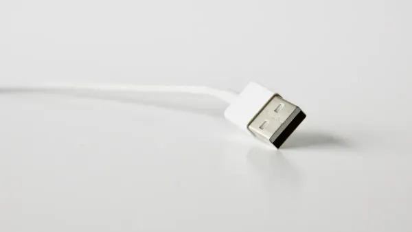
You often see the USB A connector when you work with electronic components and integrated circuits. USB stands for universal serial bus. The USB A connector has a flat, rectangular shape. You find it on computers, chargers, and many devices. This connector is known for its reliability and wide use. The usb a male pinout shows the exact order and function of each pin inside the connector. When you look at a usb a pinout, you see how each pin helps send power or data between devices.
| Characteristic | USB Type A | Other USB Types |
|---|---|---|
| Shape | Rectangular | Varies (Micro, Mini) |
| Compatibility | USB 1.1, 2.0, 3.0 | Varies |
| Backward Compatibility | Yes | Varies |
| Number of Pins (USB 3.0) | 9 | Varies |
The USB A connector stands out because it works with many versions and devices. You can use it for both old and new equipment.
Pin Arrangement
The pin arrangement in a usb a connector is important for safe and fast connections. Each pin has a job. Some pins carry power, while others move data. If you use the wrong pin, you might damage your device or lose data. The usb pinout helps you avoid these problems.
Here is a simple usb a diagram for USB 2.0:
| Pin | Signal | Color | Description |
|---|---|---|---|
| 1 | Vcc | Red | +5V Power |
| 2 | D- | White | Data- |
| 3 | D+ | Green | Data+ |
| 4 | GND | Black | Ground |
- USB 1.0 and 2.0 pins deliver up to 500 mA (0.5A) of power.
- USB 3.0 pins deliver up to 900 mA (0.9A), which means more power for devices.
The type-a usb connector pinout lets you connect microcontrollers, sensors, and other parts safely. When you follow the correct pinout, you make sure your circuits get the right power and data. Always check the pin arrangement before you connect anything.
USB Pinout Diagram
Pin Numbering
When you look at a usb a male pinout, you see that each pin has a number and a specific role. The industry-standard method for numbering pins on a usb connector starts from the left when you hold the connector with the pins facing up. This numbering helps you identify the correct pin for power, data, or ground in your electronic components and integrated circuits.
Here is a simple table showing the pin numbering for USB 2.0:
| Pin # | Pin Description | Colour | Function |
|---|---|---|---|
| 1 | +5V | Red | Power |
| 2 | Data – | Blue | Negative signal |
| 3 | Data + | Yellow | Positive signal |
| 4 | Ground | Brown | Ground |
For USB 3.0, you get more pins. The connector has two rows: five pins on the top and four on the bottom. This extra row supports faster data transfer and more power.
| USB Version | Number of Pins | Arrangement |
|---|---|---|
| USB 2.0 | 4 | Single row |
| USB 3.0 | 9 | Two rows (5 top, 4 bottom) |
Tip: Always check the pin numbering before you connect your usb cable to any circuit. This step helps you avoid mistakes and keeps your devices safe.
Pin Functions
Each pin in the usb pinout has a unique function. In USB 2.0, you find four main pins:
- Pin 1: Provides +5V power to your device.
- Pin 2: Carries the negative data signal (D-).
- Pin 3: Carries the positive data signal (D+).
- Pin 4: Connects to ground.
In USB 3.0, you see nine pins. The extra pins allow for higher speeds and better performance in your electronic projects. Here is a table showing the functions for USB 3.0:
| Pin Number | Function |
|---|---|
| 1 | Provides +5V power supply |
| 2 | Differential data line for negative signal (D-) |
| 3 | Differential data line for positive signal (D+) |
| 4 | Ground connection (GND) |
| 5 | SuperSpeed receiver differential pair (negative) |
| 6 | SuperSpeed receiver differential pair (positive) |
| 7 | Ground for signal return (GND_DRAIN) |
| 8 | SuperSpeed transmitter differential pair (negative) |
| 9 | SuperSpeed transmitter differential pair (positive) |
You use the usb pinout to connect microcontrollers, sensors, and other integrated circuits. USB 2.0 cables have four wires for basic power and data. USB 3.0 cables have nine wires, which means you get faster data transfer and more power for advanced projects.
- USB 2.0: Four pins, single row, basic power and data.
- USB 3.0: Nine pins, two rows, supports higher speeds and more power.
You see usb connector types in many devices. Knowing the usb a pinout helps you build and repair electronic circuits with confidence. The universal serial bus standard makes it easy to connect different components safely.
Type-A USB Connector Pinout
When you work with electronic components and integrated circuits, understanding the type-a usb connector pinout helps you make safe and reliable connections. The usb pinout shows you how each pin in the usb a connector works to deliver power, transfer data, and protect your devices. You can use a usb a diagram to identify each pin and its role in your circuit.
Power Pins
The power pin in the usb a pinout is called VBUS. This pin supplies power to your devices and circuits. You use VBUS to power microcontrollers, sensors, and other electronic parts. The universal serial bus standard sets the voltage and current for VBUS, so you know what your components will receive.
| Parameter | Value |
|---|---|
| Voltage Rating | 5V |
| Current Rating | Up to 1A |
You rely on VBUS to charge devices and run low-power circuits. Some devices only use VBUS and GND for power, without needing data transfer. The usb a connector cannot select higher voltages under the official standard. If you need more power, you must use special technology that goes beyond the standard.
| Aspect | Description |
|---|---|
| VBUS Pin Role | Essential for providing power in USB connectors. |
| USB-A Limitations | Limited in supporting full USB Power Delivery specifications compared to USB-C connectors. |
| Power-Only Devices | Some devices use only VBUS and GND without data transfer capabilities. |
Tip: Always check the voltage and current rating before you connect your usb cable to any electronic component. This step helps you avoid damage and keeps your circuit safe.
- USB-A connectors cannot deliver or select higher voltages under the official USB standard.
- Proprietary technology is required for higher voltage delivery, which deviates from the standard.
Data Pins
The usb pinout includes two data pins: D+ and D-. These pins let you send and receive information between your devices and integrated circuits. You use D+ and D- to transfer data, update firmware, or communicate with sensors.
| Pin | Role |
|---|---|
| D+ | Positive data signal line enabling bidirectional data transfer. |
| D- | Negative data signal pin that works with D+ to transfer data. |
- D+ and D- pins are crucial for data transmission protocols.
- They enable bidirectional data transfer between devices.
- They operate on a differential pair approach to minimize electromagnetic interference.
You see these pins in every usb connector type. The differential pair design helps your circuit avoid noise and interference, so your data stays accurate. When you use the usb a male pinout, you make sure your microcontroller or sensor gets the right signals for communication.
Ground and Shielding
The ground pin (GND) in the usb pinout gives your circuit a safe reference point for all electrical signals. You use GND to complete the power circuit and protect your devices from voltage spikes. The ground pin also connects to the shielding in the usb cable, which keeps your data safe from outside interference.
- The GND pin provides a common reference point for electrical signals.
- It helps ground the shielding of the USB cable, protecting against electromagnetic interference (EMI).
- It directs unwanted noise or voltage spikes away from the device, enhancing safety.
Shielding in usb cables uses conductive materials to block outside electromagnetic fields. The shielding layer creates currents that fight interference, so your data stays stable and accurate.
- Shielding layers in USB cables are made of conductive materials that help isolate and minimize the impact of external electromagnetic fields.
- The shielding layer generates induced currents that create an opposing electromagnetic field, offsetting interference during data transmission.
- This process ensures stable and accurate data transmission by protecting internal signals from external electromagnetic interference.
You need to understand the type-a usb connector pinout when you design or repair electronic components and integrated circuits. The usb pinout helps you deliver power, transfer data, and keep your devices safe from interference. You can use a usb a diagram to check the pinout before you connect anything. This step makes your work easier and protects your equipment.
USB Pinout Uses
Devices
You find USB A male connectors in many devices that work with electronic components and integrated circuits. These connectors help you link your projects to computers, chargers, and other host devices. The universal serial bus standard makes USB A connectors reliable for both old and new equipment. You see them in gaming consoles, DVD players, and automotive audio systems. These devices use the usb a male pinout to send power and data to your circuits. The usb pinout lets you connect sensors, microcontrollers, and other parts safely.
| Device Type | Example Use Case |
|---|---|
| Gaming Console | Connect controllers and accessories |
| DVD Player | Transfer media files |
| Automotive Audio | Play music from USB drives |
| Computer | Interface with peripherals |
| Charger | Power electronic projects |
Tip: Always check the usb a pinout before you connect your device. This step helps you avoid mistakes and keeps your components safe.
DIY and Repairs
You often need to repair or modify USB A male connectors in your electronic projects. The usb pinout helps you fix broken connections and build custom cables for integrated circuits. Many DIY repairs involve resoldering wires or replacing damaged connectors. You use tools like soldering irons, pliers, and multimeters to work on these repairs.
Common DIY repair tasks include:
- Resoldering broken USB connections.
- Stripping and cleaning damaged connectors.
- Testing connections with a multimeter.
- Securing the connector with hot glue.
- Tin the wires to prepare for soldering.
- Strip and clean the damaged connector.
- Solder each wire to the correct pinout position.
- Test the connection before reassembling.
- Secure the connector with hot glue.
Recommended tools and materials:
- Soldering iron
- Hot air station or heat-gun
- Hot-glue gun
- Precision knife
- Third hand clamps
- Multimeter
- Pliers
- Lead-free or leaded solder
- Rosin flux
- Electrical tape
- Heat-shrink
Note: Some repairs require experience and specialized tools. If you feel unsure, ask an experienced technician for help.
You use the usb pinout to troubleshoot and repair connections in electronic components and integrated circuits. Understanding the usb a male pinout lets you build, fix, and test your projects with confidence.
Troubleshooting USB A Pinout
Pin Issues
When you work with electronic components and integrated circuits, you may face problems with usb a pinout connections. Some common issues can stop your devices from working as expected. You might notice that your device is not recognized by your computer. This often happens when the host cannot detect or identify the connected device. Sometimes, your device does not receive power. This can occur if the VBUS or GND pins are not connected properly or if the power source fails. Data transfer problems or connection failures may also happen. Damaged cables or loose data pins often cause these issues.
Here are some common pinout-related problems you may encounter:
- Device not recognized by the host
- Device not receiving power
- Data transfer issues or connection failures
To find faulty pins in usb type a cables, you can use several diagnostic methods:
| Diagnostic Method | Description |
|---|---|
| Continuity Test | Checks if the wires inside the usb cable connect properly for smooth data transmission. |
| Resistance Test | Measures wire resistance to spot breaks or damage that affect conductivity. |
| Voltage Level Test | Checks voltage across power lines to ensure your device gets the right power. |
You can use a multimeter for these tests. Always check the usb pinout before connecting your devices to avoid these problems.
Safety Tips
You must handle usb connectors with care to protect both your devices and yourself. Place your equipment on a hard, level surface to prevent falls. Make sure nothing rests on your cables, as this can cause damage. Never use your equipment in a wet environment. Always disconnect from the electrical outlet before cleaning.
Follow these safety practices:
- Work with electrical connections only when the power is off.
- Choose high-quality products that meet safety standards.
- Inspect outlets and cables for signs of wear or malfunction.
- Teach family members about safe usage.
If you feel unsure about testing or repairing a usb connector, ask a qualified technician for help. Avoid common mistakes such as forcing connectors, using damaged cables, or ignoring bent pins. Always check for physical damage, make sure your device gets enough power, and test different ports and cables if you have connection problems.
Tip: Safe handling and regular checks help you avoid hazards and keep your universal serial bus devices working for charging and data transfer.
You now understand how the usb pinout helps you connect electronic components and integrated circuits safely. Knowing each pin’s role in the universal serial bus reduces device damage and improves troubleshooting.
- Misinterpreting pin configurations can cause data loss or power issues.
- This guide gives you a quick reference for usb A connectors.
- Always check diagrams before repairs or installations.
- Use the usb pinout to keep your projects running smoothly.
FAQ
What happens if you connect the wrong pin in a usb A male connector?
You risk damaging your electronic components or integrated circuits. The usb pinout ensures each pin has a specific job. Always check the pinout before connecting to avoid short circuits or data loss.
Can you use a usb A male connector for both power and data in circuits?
Yes, you can use a usb A male connector for power and data. The universal serial bus standard allows you to send power to your circuit and transfer data between devices at the same time.
How do you identify the correct pinout on a usb A male connector?
You can use a usb pinout diagram. Hold the connector with the pins facing up. Match each pin to its function using the diagram. This helps you connect your integrated circuits safely.
Why does shielding matter in usb cables for electronic projects?
Shielding protects your data signals from outside interference. When you use usb cables with shielding, your integrated circuits receive stable signals. This keeps your projects reliable and accurate.
Can you repair a broken usb A male connector at home?
You can repair a broken usb A male connector if you have basic tools. Use a soldering iron and a usb pinout diagram. Always test your connections before using the repaired cable in your electronic components.


