

RJ45 Pinout Guide T568A vs T568B Explained
When you look at an ethernet pinout rj45, the only physical difference between the T568A and T568B wiring standards is a sim
When you look at an ethernet pinout rj45, the only physical difference between the T568A and T568B wiring standards is a simple swap. The orange and green wire pairs trade places on pins 1, 2, 3, and 6. For your network connection to work, the most crucial rule is to use the same standard on both ends of a single ethernet cable. This creates a functional pinout for your electronic communication hardware.
Note: You will find T568B is the more common standard for new network installations. The T568A standard is often required for U.S. government contracts to ensure backward compatibility and consistency in federal wiring projects.
Key Takeaways
- T568A and T568B are two ways to arrange wires inside an ethernet cable. They only differ by swapping the orange and green wire pairs.
- Always use the same wiring standard on both ends of a single ethernet cable for it to work correctly.
- T568B is the most common standard for new networks in the U.S., while T568A is often used for government projects or older systems.
- A straight-through cable uses the same wiring standard on both ends. A crossover cable uses T568A on one end and T568B on the other, but modern devices often do not need them.
- Wiring your own cables requires specific tools and careful steps to ensure a reliable network connection.
Understanding the Ethernet Pinout RJ45
To master network cabling, you must first understand the map that guides it: the ethernet pinout rj45. This pinout is a specific arrangement of the eight wires inside an ethernet cable. These wires are inserted into an RJ45 connector. The arrangement ensures that data signals travel correctly between your electronic communication hardware. The two approved standards for this wiring are T568A and T568B.
The T568A Wiring Standard
The T568A standard is one of two official wiring schemes. You will often find this pinout in existing networks or in projects for the U.S. government. The T568A rj45 color code arranges the colored wire pairs to optimize signal integrity and minimize interference. Following this standard is critical for your ethernet cable to pass certification and function reliably.
This rj45 pinout diagram shows the correct wire order for the T568A standard.
| Pin | Color | Signal | Pair |
|---|---|---|---|
| 1 | White/Green | Transmit + | 3 |
| 2 | Green | Transmit - | 3 |
| 3 | White/Orange | Receive + | 2 |
| 4 | Blue | Unused | 1 |
| 5 | White/Blue | Unused | 1 |
| 6 | Orange | Receive - | 2 |
| 7 | White/Brown | Unused | 4 |
| 8 | Brown | Unused | 4 |
Why Standards Matter: Official standards like ANSI/TIA-568-C.2 define strict performance metrics for cable wiring. These include factors like Near End Crosstalk (NEXT) and Insertion Loss. Adhering to a pinout like T568A ensures your ethernet connection meets these requirements for high-speed data transmission.
The T568B Wiring Standard
The T568B standard is the most prevalent wiring scheme for new network installations in homes and businesses today. Functionally, it performs identically to T568A. The choice to use T568B is mostly based on convention. If you are setting up a new network without any specific requirements, T568B is the standard you will likely use for your RJ45 connectors.
This rj45 pinout diagram details the T568B rj45 color code. Notice the difference in the green and orange pairs compared to the T568A wiring.
| Pin | Color | Signal | Pair |
|---|---|---|---|
| 1 | White/Orange | Transmit + | 2 |
| 2 | Orange | Transmit - | 2 |
| 3 | White/Green | Receive + | 3 |
| 4 | Blue | Unused | 1 |
| 5 | White/Blue | Unused | 1 |
| 6 | Green | Receive - | 3 |
| 7 | White/Brown | Unused | 4 |
| 8 | Brown | Unused | 4 |
The Key Difference: A Simple Pair Swap
The only difference between the T568A and T568B standards is a swap of two wire pairs: the orange pair and the green pair. The blue and brown pairs remain in the exact same position on the RJ45 connector.
This swap involves the wires on pins 1, 2, 3, and 6. This change directly affects how a device transmits and receives data. The integrated circuits in network devices are designed to transmit data on one pair and receive it on another. Swapping these pairs on one end of a cable changes which pins receive the data signal.
This rj45 connector diagram highlights the simple swap.
| Pin | T568A RJ45 Color Code | T568B RJ45 Color Code |
|---|---|---|
| 1 | White/Green | White/Orange |
| 2 | Green | Orange |
| 3 | White/Orange | White/Green |
| 4 | Blue | Blue |
| 5 | White/Blue | White/Blue |
| 6 | Orange | Green |
| 7 | White/Brown | White/Brown |
| 8 | Brown | Brown |
This strategic swap is the foundation for creating different types of ethernet cables. When you connect two computers directly, their transmit pins would align without this swap, causing signal collisions. By using a different standard on each end of a cable, you ensure one device's transmit pins connect to the other's receive pins. This allows for successful communication.
Which Standard Should You Use?
Deciding between T568A and T568B can feel confusing, but the choice is usually straightforward. Your decision will depend on the project's requirements and location. Following a few simple rules will ensure your network connections are reliable and meet industry specifications.
Rule #1: Consistency is Key
The most important rule you need to follow is to match the standard already in place. If you are adding to or repairing an existing network, you must identify which wiring standard was used and stick with it.
What happens if you mix them? When you terminate one end of a cable with the T568A standard and the other end with T568B, you create a crossover cable. This special configuration swaps the transmit and receive pairs. While modern network devices often have a feature called Auto-MDIX that can automatically correct for this, older hardware may not. This mismatch can lead to a complete loss of connectivity. Always check the existing wiring at the patch panel or wall jack before making a new ethernet cable.
For New Networks: Why T568B is the Default
If you are setting up a brand-new network in the United States with no pre-existing wiring, T568B is the standard you should use. Its popularity is the main reason for this recommendation.
The T568B standard became the popular choice for several historical reasons:
- It aligns with older wiring patterns established by AT&T, so many businesses adopted it early on.
- Most pre-terminated ethernet patch cables you buy are wired to the T568B standard.
- This widespread use made it the default for most commercial and residential network installations.
By choosing T568B for your new network, you align your project with the most common convention in the U.S. This makes future troubleshooting and expansion simpler for you or other technicians.
When to Use T568A
While T568B is more common, there are specific situations where the T56A standard is the correct choice. You should choose the T568A standard to maintain consistency and meet specific requirements.
You will need to use the T568A rj45 wiring in these cases:
- U.S. Government Projects: The U.S. government requires contractors to use the T568A standard for all federal projects. This mandate ensures that the ethernet pinout rj45 is uniform across all government facilities, preventing wiring inconsistencies.
- Backward Compatibility: The T568A standard was designed for better backward compatibility with older one-pair and two-pair USOC telephone wiring systems. If you are upgrading the wiring in an older building, T568A might be the required choice.
- International Projects: This standard is more common in other parts of the world, including many European and Pacific countries.
- Existing T568A Networks: As mentioned in our first rule, if you are working on any network that already uses T568A for its RJ45 connectors, you must continue to use it.
How Pinouts Create Cable Types
The RJ45 pinout you choose directly creates different types of ethernet cables. Your decision to use the same or different standards on each end of a cable determines how the electronic signals travel between devices. Understanding this helps you select the right cable for any network connection.
Straight-Through Cables
You create a straight-through cable when you wire both ends with the same standard. This means you use either T568B on both ends or T568A on both ends. This is the most common type of ethernet cable you will encounter. The pinout ensures that Pin 1 on the first connector links directly to Pin 1 on the second, Pin 2 to Pin 2, and so on. This configuration connects the transmit (TD) pins of one device to the receive (RD) pins of another, which is necessary when connecting different types of devices.
You will use a straight-through cable for connections like:
- Connecting a computer to a switch or router
- Connecting a router to a switch to expand your network
- Connecting a network printer to a switch
Crossover Cables
You make a crossover cable by wiring one end as T568A and the other end as T568B. This special pinout swaps the transmit and receive wire pairs. The transmit pins on one device's RJ45 port connect directly to the transmit pins on the other device. This was once essential for connecting two similar devices, like two computers, without a switch in between. The crossover pinout correctly routes the signals between their internal integrated circuits. These cables are much less common today because of modern network technology.
The Role of Auto MDI-X
Modern ethernet devices have a smart feature that makes crossover cables mostly obsolete. This feature is called Automatic Medium-Dependent Interface Crossover (Auto MDI-X).
How it Works: Auto MDI-X allows a device's network port to automatically detect what kind of cable is connected. The port then electronically switches its pin functions, reconfiguring its transmit and receive signals internally.
This technology is built into most modern routers, switches, and computer network cards. It automatically adjusts the connection for you. This means you can almost always use a standard straight-through cable for any connection, which greatly simplifies setting up a network.
How to Wire an RJ45 Connector
Wiring your own ethernet cables gives you full control over your network setup. This guide will walk you through the process step-by-step. You can create custom-length cables for a clean and professional installation.
Essential Tools and Materials
Before you begin your cable wiring project, you need to gather the right tools and materials. Having everything ready makes the process much smoother.
You will need the following items:
- Bulk Ethernet Cable: Choose the category you need, like Cat5e or Cat6.
- RJ45 Connectors: These male plugs come in different types. You can find shielded RJ45 plugs for environments with interference or standard unshielded ones for home use.
- Cable Stripper: A dedicated network cable and wire stripper is ideal for removing the outer jacket without damaging the inner wires.
- RJ45 Crimping Tool: This tool secures the RJ45 connector to the cable. Some crimpers also cut the wires, which is helpful for pass-through connectors.
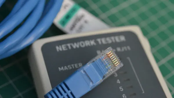
- Network Cable Tester: This device verifies that your wiring is correct and the connection is good.
Preparing the Ethernet Cable
Proper preparation is key to a successful connection. You must expose the inner wires correctly.
- Use your cable stripper to carefully cut and remove about 5 to 6 cm (around 2 inches) of the outer jacket from the end of the ethernet cable. This length gives you enough room to work with the wires.
- You will see four twisted pairs of wires. Gently untwist each pair and spread them out.
- Straighten each of the eight individual wires as much as possible. You want them to be flat and parallel to each other.
Arranging Wires and Crimping
This is the most critical step. Your attention to detail here determines if the cable will work.
- Arrange the eight wires in the correct order. You must choose either the T568A or T568B rj45 color code and stick with it. For a standard straight-through cable, use the same wiring standard on both ends.
- Once the wires are in order, flatten them and trim the ends so they are all the same length.
- Carefully slide the wires into the RJ45 connector. Make sure each wire goes into its correct channel and extends all the way to the end of the plug. The copper pins inside the connector must make contact with each wire.
- Place the RJ45 connector into your crimping tool and squeeze the handles firmly. This action pushes the pins through the insulation to create a solid electrical connection and secures the cable.
Final Check: After crimping both ends, use a network cable tester. A good tester performs a continuity and wiremap test. It confirms that all pins are connected correctly and that your rj45 color code matches from end to end. This ensures your new cable will support reliable network communication.
The ethernet pinout rj45 difference is just a swap of the orange and green wire pairs. Your choice of wiring standard does not affect network performance. For any project, you should first match the existing wiring. For a new network, the T568B standard is the common choice. Using the same pinout on both ends of an ethernet cable creates a straight-through connection. Using a different pinout on each end creates a crossover cable, though modern devices often make this unnecessary. Understanding this simple pinout rule is a key step to mastering your rj45 connections.
FAQ
### Does T568B offer better performance than T568A?
No, T568B does not perform better than T568A. Both standards support the same network speeds and signal quality. The integrated circuits in your network hardware process the electronic signals identically regardless of the standard used. The most important factor for performance is using the same standard on both ends.
### Can I plug a T568A cable into a T568B jack?
Yes, you can. Modern network devices use Auto MDI-X. This feature lets the port's internal electronics automatically detect the wiring and adjust. Your connection will work fine. However, for consistency in a network installation, you should always match your cable standard to your jack standard.
### Why is T568B more common if they are the same?
T568B became the popular choice in the U.S. due to convention. It was compatible with older AT&T wiring codes. As a result, most manufacturers and installers adopted it for new commercial and residential projects. This widespread use makes it the default for new communication hardware setups.
### What happens if I wire a cable wrong? 😥
If you wire a cable incorrectly, it will likely fail a continuity test. The electronic signals will not travel to the correct pins on the receiving device's integrated circuit. This can result in a slow connection, intermittent data loss, or a complete failure to connect to the network.


