

Unlock Electronics With The Impedance Formula
You can think of impedance (Z) as the total opposition a circuit presents to alternating current (AC). Your under
You can think of impedance (Z) as the total opposition a circuit presents to alternating current (AC). Your understanding of impedance is crucial. It combines resistance, capacitance, and inductance to predict how signals behave. The global power electronics market, valued at over USD 36 billion, shows how vital AC systems are.
Imagine DC resistance as a constant traffic jam. In contrast, impedance is like traffic that changes with the time of day, which represents frequency. The impedance of a circuit determines its performance. This makes the impedance formula a recipe to analyze any AC circuit. Your grasp of impedance and resistance unlocks electronics.
Key Takeaways
- Impedance is the total opposition to current in AC circuits. It includes resistance and reactance, which changes with frequency.
- The impedance formula, Z = R + jX, helps you understand how circuits behave. 'R' is resistance, and 'jX' is reactance, which stores and releases energy.
- Impedance is important for many things. It helps you use Ohm's Law for AC, design filters, and match impedance for good power transfer.
- Resistance is a constant opposition to current. Reactance changes with the signal's frequency. This difference is key to how AC circuits work.
- You can calculate impedance for series and parallel circuits. This helps you understand how different parts of a circuit work together.
The Impedance Formula Explained
You are now ready to break down the master recipe for AC analysis: the impedance formula. This formula, Z = R + jX, is the key to understanding how a circuit behaves. Each part of this equation tells you something unique about the opposition to current. Let's look at the components.
- Z is impedance (in ohms): This is the total opposition your circuit presents to alternating current.
- R is resistance (in ohms): This part represents energy lost as heat.
- jX is the reactance (in ohms): This part represents energy stored and released by components.
- j is the imaginary unit (√-1): This special operator shows you the phase angle, or timing difference, between voltage and current.
This simple impedance formula combines these elements to give you a complete picture of your circuit's behavior.
Resistance (R): The Real Part
You can think of resistance (R) as the straightforward part of impedance. It represents the opposition to current that dissipates energy, usually as heat. This is the same resistance you are familiar with from DC circuits. It is the "real" part of the impedance because it behaves predictably, regardless of the AC signal's frequency.
Many common household items are examples of purely resistive loads. You see this principle in action with:
- Water heaters
- Irons
- Electric ranges
- Old-fashioned incandescent light bulbs
However, you must remember that resistance is not always constant. Temperature can change a component's resistance. When temperature rises, the resistance of wires can increase, causing current to drop. This shows how even small environmental changes can affect a circuit. You can see how different materials react to heat in the table below.
| Type of Temperature Coefficient | Effect of Temperature Increase on Resistance |
|---|---|
| Positive Temperature Coefficient (PTC) | Resistance increases |
| Negative Temperature Coefficient (NTC) | Resistance decreases |
| Zero or Near-Zero Temperature Coefficient | Resistance remains nearly constant |
Reactance (X): The Frequency-Dependent Part
Now we move to the exciting part of impedance: reactance (X). Unlike resistance, reactance is the opposition to current that depends entirely on the signal's frequency. It does not burn off energy as heat. Instead, it stores and releases energy in electric or magnetic fields. This is why impedance changes with frequency.
You find reactance in two types of components: capacitors and inductors.
- Capacitive Reactance (XC): A capacitor stores energy in an electric field. In an AC circuit, the capacitor charges and discharges as the voltage flips back and forth. At high frequencies, the voltage changes so quickly that the capacitor has little time to charge. This results in less opposition, meaning low reactance.
- Inductive Reactance (XL): An inductor stores energy in a magnetic field. An AC current creates a constantly changing magnetic field. This changing field creates a voltage that opposes the original current flow. At high frequencies, the rapid changes create a stronger opposing force, meaning high reactance.
The total reactance in a circuit is the combination of these two effects. The complete impedance function must account for both.
The 'j' Operator: Phase And Complex Numbers
You might wonder what the 'j' is for in the formula Z = R + jX. The 'j' operator is a tool from mathematics that helps you handle the phase angle. In electronics, 'j' represents the square root of -1. You use 'j' instead of the traditional 'i' because 'i' is already used for electric current. This simple change prevents a lot of confusion.
The 'j' operator's main job is to signify a 90-degree rotation. It separates the real part (resistance) from the imaginary part (reactance). This separation is vital because it reflects the timing difference, or phase angle, between voltage and current in reactive components.
In a purely inductive circuit, the current lags the voltage by a 90-degree phase angle. In a purely capacitive circuit, the current leads the voltage by a 90-degree phase angle. The 'j' operator mathematically represents this 90-degree shift.
This allows you to map impedance on a 2D plane, with resistance on the horizontal axis and reactance on the vertical 'j' axis. This visual separation makes complex impedance much easier to analyze. The table below shows how 'j' is used in the impedance formulas for inductors and capacitors, highlighting its role in defining the phase angle.
| Circuit Component | Complex Impedance Formula | Role of 'j' Operator |
|---|---|---|
| Inductor | ZL = jωL | Represents the imaginary component, indicating a +90-degree phase angle. |
| Capacitor | ZC = 1/(jωC) or -j/(ωC) | Represents the imaginary component, indicating a -90-degree phase angle. |
Applying Impedance In AC Circuits
You have now learned the "what" and "why" of impedance. It is time to see how you can apply this knowledge in real-world electronics. Understanding the impedance formula is your ticket to designing and troubleshooting circuits that handle changing signals, from audio to high-speed data. Let's explore three critical applications where impedance takes center stage.
Ohm's Law For AC: V = I * Z
You are likely familiar with Ohm's Law for DC circuits: V = I * R. For AC circuits, you must upgrade this fundamental rule. You will use the AC version of Ohm's Law: V = I * Z. This simple change is powerful. It accounts for not just resistance but also the reactance of capacitors and inductors.
Using the AC version of Ohm's Law is essential because impedance includes a phase angle. This angle tells you the timing difference between your voltage and current peaks. Ignoring reactance and using only resistance for your calculations will give you the wrong answers.
Let's see Ohm's Law in action with a practical example.
Problem: Imagine you have a series rlc circuit with a 20V AC source running at a frequency (ω) of 1000 rad/s. The circuit contains a 400 Ω resistor, a 400 mH inductor, and a 200 µF capacitor. What is the current (I) flowing through the circuit?
Here is how you solve it step-by-step:
- Calculate Individual Impedances: First, you find the impedance of each component.
- Resistor (R):
Z_R = 400 Ω - Inductor (L):
Z_L = jωL = j * 1000 * 0.4 = j400 Ω - Capacitor (C):
Z_C = 1/(jωC) = -j/(1000 * 0.0002) = -j5 Ω
- Resistor (R):
- Calculate Total Impedance (Z): Next, you add them up. Since this is a series circuit, the total impedance is the sum of the individual parts.
Z = Z_R + Z_L + Z_CZ = 400 + j400 - j5 = 400 + j395 Ω
- Apply Ohm's Law for AC: Now, you use the full Ohm's Law,
I = V / Z. You need to convert Z into polar form to make the division easier.- Magnitude:
|Z| = √(400² + 395²) = 562.16 Ω - Phase Angle:
θ = arctan(395/400) = 44.64° - So,
Z = 562.16∠44.64° Ω
- Magnitude:
- Find the Current: Finally, you can calculate the current.
I = 20∠0° V / 562.16∠44.64° ΩI = 0.0356∠-44.64° A
The result shows a current of 35.6 mA that lags the voltage by 44.64 degrees. If you had incorrectly used only the 400 Ω resistance, you would have calculated a current of 20V / 400Ω = 50 mA, which is wrong. This example proves that you must use the total impedance for accurate AC circuit analysis.
Signal Filtering With Reactance
One of the most common uses for reactance is creating signal filters. Filters allow you to block or pass signals of specific frequencies. This is possible because the reactance of capacitors and inductors changes with frequency.
- Low-Pass Filters: A capacitor's reactance decreases as frequency increases. If you place a capacitor in parallel with your signal path (connecting it from the signal line to ground), it creates a low-pass filter. Low-frequency signals see the capacitor as a high impedance path and continue to the output. High-frequency signals (like noise) see the capacitor as a low impedance path and are diverted to ground. This is a common way to get clean power from a noisy supply.
- High-Pass Filters: An inductor's reactance increases with frequency. If you place an inductor in series with your signal path, it creates a high-pass filter. The inductor presents a high impedance to high-frequency signals, forcing them to find another path, while it has a low impedance to low-frequency signals. However, it is more common to build a high-pass filter by placing a capacitor in series. The capacitor blocks low-frequency DC while allowing high-frequency AC signals to pass through.
You can combine these components to make more advanced filters. For example, ferrite beads are special inductors designed to suppress high-frequency noise. They act as an inductor at low frequencies but become more like a resistance at very high frequencies, converting noise energy into heat. This makes them excellent for cleaning up power supply lines in a circuit.
Impedance Matching For Power Transfer
Have you ever connected a tiny pair of headphones to a massive concert amplifier? The sound would be terrible. This is because of an impedance mismatch. Impedance matching is the process of making the load impedance equal to the source impedance. This is critical for two main reasons: maximum power transfer and signal integrity.
The Maximum Power Transfer Theorem states that to deliver the most power from a source to a load, the load impedance must be the complex conjugate of the source impedance. If your source has an impedance of R + jX, your load must have an impedance of R - jX for peak efficiency.
A classic example is an audio amplifier (source) and a speaker (load). If an 8 Ω amplifier is connected to an 8 Ω speaker, you get the best possible power transfer, resulting in loud and clear sound. If you connect that same amplifier to a 4 Ω speaker, the impedance mismatch can cause the amplifier to overheat or even get damaged.
This concept is even more critical in high-frequency circuits, like those for radio antennas or high-speed data. In these systems, an impedance mismatch causes signals to reflect from the load back to the source. These reflections can cause several problems:
- Reduced Power Transfer: The reflected signal is wasted power that never reaches its destination.
- Signal Distortion: Reflected waves can interfere with the original signal, causing errors and noise.
- Component Stress: The reflected power can return to sensitive components like power amplifiers and damage them.
On a printed circuit board (PCB), maintaining a constant impedance is crucial for signal integrity. As frequencies rise, every part of the circuit—from the tiny copper traces to the connectors—contributes to the overall impedance function. Differences in impedance between components will cause signal reflections and degradation. This is a challenge that companies like Nova Technology Company (HK) Limited, a HiSilicon-designated (authorized) solutions partner, work to solve in real-world high-speed digital designs.
The physical design of a PCB has a huge impact on impedance. You must control these factors carefully to ensure your circuit works as designed.
| Factor | Relationship to Impedance | Impact on Signal Integrity |
|---|---|---|
| Trace width (W) | Inversely proportional | Wider traces have lower impedance. |
| Distance to ground plane (H) | Directly proportional | Greater distance results in higher impedance. |
| Vias (vertical connections) | Can cause discontinuities | Vias introduce impedance changes, causing reflections. |
| Connectors and component pads | Can cause discontinuities | Mismatches here lead to reflections and signal loss. |
By mastering the concepts behind the impedance formula, you gain the ability to apply Ohm's Law correctly, design effective filters, and ensure maximum power and signal integrity through proper impedance matching.
Calculating Impedance In Practice
You now understand the concepts behind impedance. It is time to perform some practical impedance calculations. While professionals in a lab use advanced tools to measure impedance, you can calculate it with the formulas you have learned.
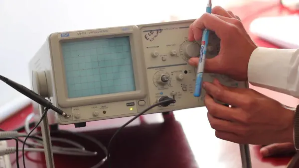
Real-World Tools 🔬 In a professional setting, you would use specialized equipment to measure the impedance of a circuit. Common instruments include:
- LCR meters (like the LCR-1)
- Network analyzers
- Impedance analyzers (such as the ISX-3 or ISX-5)
- Oscilloscopes
Learning to calculate impedance by hand gives you a deep understanding of how a circuit works.
Series And Parallel Circuits
You calculate total impedance in a circuit much like you do with resistance. However, you must use complex numbers to account for reactance. The method changes depending on how the components are arranged.
For a series circuit, your job is simple. You find the total impedance by adding the individual impedances. You combine all the real parts (resistance) and all the imaginary parts (reactance) separately.
- Formula:
Z_total = R + jX_L - jX_C - Example: If you have a circuit with 500 Ω resistance, an inductive reactance of
j188.5 Ω, and a capacitive reactance of-j294.7 Ω, the total impedance is500 + j188.5 - j294.7, which simplifies to500 - j106.2 Ω.
For a parallel circuit, you use the reciprocal rule. The total impedance is found with the formula 1/Z_total = 1/Z_1 + 1/Z_2 + .... For a complex series rlc circuit, you break it down into smaller series and parallel parts.
Inductive Reactance (XL = jωL)
Inductive reactance is the opposition an inductor presents to current. You calculate it with the formula XL = jωL. Here, ω is the angular frequency and L is the inductance. The 'j' tells you the voltage leads the current by 90 degrees. The key takeaway is that inductive reactance increases with frequency. This means an inductor has a higher impedance to high-frequency signals, effectively blocking them. This property is essential for designing filters in a circuit.
Capacitive Reactance (XC = 1/jωC)
Capacitive reactance is a capacitor's opposition to current. You find it using the impedance function XC = 1/(jωC), which is the same as -j/(ωC). This formula shows that capacitive reactance is inversely proportional to frequency. As the signal frequency increases, the capacitor's impedance decreases.
For example, a 220 nF capacitor in a 1 kHz circuit has a certain reactance. If you increase the frequency to 20 kHz, its reactance drops significantly. This low impedance path for high frequencies makes capacitors perfect for filtering out unwanted noise from a circuit. The changing reactance is a core part of how impedance works.
You now see that impedance is the crucial bridge from static DC theory to the dynamic world of AC circuits. Understanding the impedance formula is about conceptually grasping how components behave with changing frequencies. Mastering impedance is essential for designing filters and matching loads. Your knowledge of total circuit impedance allows for accurate analysis. This unlocked understanding of impedance empowers you to tackle more advanced projects. You can now explore topics like:
- Antenna design and impedance matching
- S-Parameter optimization
- Advanced filter design
Your journey into the true nature of impedance has just begun.
FAQ
What is the difference between impedance and resistance?
You can think of resistance as a constant opposition to current. Impedance is the total opposition, including resistance and reactance. Reactance changes with frequency. This means impedance tells you how a circuit behaves with AC signals, not just DC.
Why is the phase angle important in AC circuits?
The phase angle shows you the timing difference between voltage and current. A zero-degree phase angle means they are in sync. A non-zero phase angle indicates energy is stored, affecting power delivery. Understanding the phase angle is key to efficient circuit design.
How do you visualize impedance?
You can plot impedance on a graph. The graph shows how impedance changes with frequency. This visual is called an impedance curve. The impedance curve helps you see a component's behavior. You can also plot the phase angle to see its timing shift across frequencies.
What do impedance and phase angle curves show together?
The impedance and phase angle curves give you a complete performance summary. The impedance curve shows the magnitude of opposition. The phase angle shows the timing. Together, they reveal how a circuit will filter signals or transfer power at different frequencies.


