

IGBT vs MOSFET Sourcing: Cost-Driven Selection Tips for Power Stage Design
Expert guide on IGBT vs MOSFET Sourcing: Cost-Driven Selection Tips for Power Stage Design. Technical specs, applications, sourcing tips for engineers and buyers.
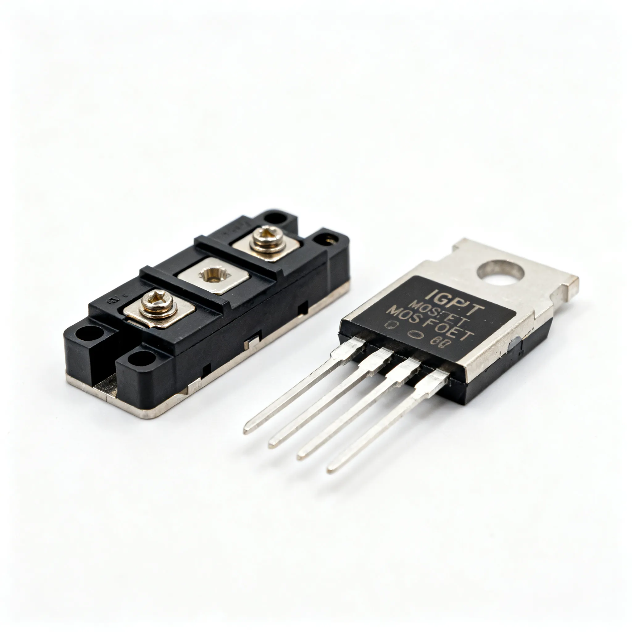
IGBT vs MOSFET Sourcing: Cost-Driven Selection Tips for Power Stage Design
The Power Semiconductor Squeeze: Why IGBT vs MOSFET Sourcing Can’t Wait
Power stage designers and procurement buyers are facing a perfect storm. Lead times for IGBTs and MOSFETs have stretched to 30 weeks or more, and several major IDMs are fully allocated on popular voltage classes. Utmel’s 2026 power semiconductor shortage outlook warns that sourcing teams must treat these lead times as highly volatile and plan procurement cycles with a minimum 6‑month buffer. The message is clear: waiting until the prototype phase to lock in power switches is no longer viable.
The squeeze isn’t limited to a single technology. iNEWS reports that supply shortages are occurring to varying degrees for mainstream products such as MOSFETs and IGBTs, with mature process capacity fully utilized. Meanwhile, 773 Group maintains stocking positions across a wide range of discrete power semiconductors—including MOSFETs, IGBTs, SiC, and GaN—and specializes in locating hard‑to‑find components through verified supply chains with full traceability documentation. That kind of support is becoming essential when every week of delay can push a product launch past the market window.
Reliability adds another layer of urgency. The Dynex AN6442 application note on IGBT module failure mechanisms details how bond wire lift‑off, solder fatigue, and thermal cycling stress can degrade modules in the field. When allocation forces you to consider alternative parts or second sources you haven’t fully qualified, understanding these failure modes becomes a cost‑avoidance tool. The decision between IGBT and MOSFET is no longer just an engineering trade‑off—it’s a sourcing strategy that directly impacts bill‑of‑materials cost, lead‑time risk, and long‑term field reliability.
IGBT and MOSFET Essentials: Voltage, Current, and Switching Frequency Trade-offs
Every power stage design starts with three fundamental parameters: maximum operating voltage, maximum operating current, and maximum switching frequency. All About Circuits succinctly captures these as the primary filters for choosing between IGBTs and MOSFETs. But cost‑driven selection demands that you go deeper—understanding how these parameters translate into conduction losses, switching losses, and thermal management requirements that ultimately define the system budget.
MOSFETs are majority‑carrier devices with a resistive on‑state, characterized by RDS(on). They switch extremely fast, often in the tens to hundreds of kilohertz, and their conduction losses scale with I²R. IGBTs, on the other hand, are minority‑carrier devices with a fixed saturation voltage VCE(sat) plus a small resistive component. This gives them a distinct advantage at high currents, where the voltage drop stays nearly constant, but they exhibit a turn‑off tail current that caps practical switching frequencies—typically below 20–50 kHz in hard‑switching applications.
IC Online’s practical guide to power MOSFET datasheets explains how to interpret RDS(on) over temperature, gate charge, and switching energy curves—skills that are equally relevant when comparing IGBT datasheets. For real‑world part selection, Infineon’s power management selection guide shows how TRENCHSTOP™ 5 IGBTs and CoolSiC™ diodes are optimized for specific frequency bands, such as 80–90 kHz inductive power transfer systems. This illustrates a critical point: the frequency boundary between IGBT and MOSFET is not fixed; it shifts with voltage class and device generation.
| Parameter | Typical IGBT (600–1200 V Class) | Typical Power MOSFET (600–900 V Si) | Impact on Cost-Driven Selection |
|---|---|---|---|
| Voltage rating | 600 V – 6.5 kV | 20 V – 900 V (Si); up to 1.2 kV with SiC | IGBT dominates above 600 V for cost‑effective high‑voltage designs |
| Current density | High (module integrates multiple dies) | Moderate; paralleling discrete MOSFETs adds PCB area and gate drive complexity | Above 50 A, IGBT modules often reduce assembly cost |
| Switching frequency (hard‑switched) | 5–50 kHz (typical); limited by turn‑off tail | 50–200+ kHz; limited by switching losses at high voltage | MOSFET wins at >50 kHz; IGBT at <20 kHz for high‑current motor drives |
| On‑state voltage drop | VCE(sat) = 1.5–2.5 V (nearly constant) | RDS(on) × ID (resistive, increases with current) | IGBT cheaper at high current where conduction losses dominate |
| Turn‑off energy (Eoff) | Higher due to tail current; strongly temperature‑dependent | Lower; fast switching with minimal tail | IGBT switching losses can erase conduction advantage above 20 kHz |
| Gate drive requirements | Voltage‑driven; requires negative bias for fast turn‑off and dv/dt immunity | Voltage‑driven; typically 10–15 V gate drive | Similar gate drive cost; IGBT may need isolated supplies for modules |
| Short‑circuit withstand time | 5–10 µs (typical) | Often lower; device‑specific | IGBT ruggedness can reduce protection circuit cost in motor drives |
| Thermal impedance (junction‑to‑case) | Module: low RthJC with isolated baseplate | Discrete: higher RthJC; paralleling reduces effective thermal resistance | IGBT module simplifies heatsink design in multi‑kW systems |
The table above distills the key electrical and thermal parameters that drive component cost and system complexity. Notice that no single parameter dictates the choice—it’s the intersection of voltage, current, and frequency that determines whether an IGBT or MOSFET yields the lowest cost per watt in your specific power stage.
Cost-Per-Watt Showdown: IGBT vs MOSFET for Power Stage Designs
The real battleground for cost‑driven selection is the mid‑range inverter and motor drive market, where power levels between 3 kW and 20 kW force a direct comparison between IGBT modules and arrays of discrete MOSFETs. Taiwan Semiconductor’s inverter analysis assumes a design requirement of peak power up to 10–20 kW and evaluates IGBTs, MOSFETs, and GaN devices side by side. Their findings confirm that at low switching frequencies (below 20 kHz), the IGBT’s constant VCE(sat) gives it a clear conduction‑loss advantage at full load, while MOSFETs pull ahead at light loads and higher frequencies due to their resistive characteristic and absence of tail current.
Shunlongwei’s 2025 selection guide goes further, arguing that for multi‑kilowatt systems the power density and thermal performance of an IGBT module are often far superior to a solution using many discrete MOSFETs in parallel. The cost of paralleling—extra gate drive channels, current‑sharing layout constraints, additional PCB layers, and larger heatsinks—can quickly erode the apparent per‑unit savings of MOSFETs. IC Online’s own deep‑dive comparisons reinforce this: selecting the right MOSFET or IGBT involves evaluating electrical, thermal, and mechanical specifications together, while understanding the cost optimization strategies requires looking beyond the transistor price to the total system cost.
| Comparison Metric | IGBT Module (e.g., 1200 V/50 A Six‑Pack) | MOSFET Array (e.g., 4× 650 V/30 A Si Super‑Junction) | Selection Criteria & Failure Boundary |
|---|---|---|---|
| Conduction loss at 50 A, 25°C | ~100 W (VCE(sat) ≈ 2.0 V) | ~90 W (RDS(on) = 45 mΩ each, 4 in parallel) | MOSFET wins at low temperature; IGBT VCE(sat) has negative temp coefficient at high current—crossover around 125°C |
| Switching loss at 10 kHz, hard‑switched | ~15 W (Eon+Eoff ≈ 1.5 mJ) | ~5 W (Eon+Eoff ≈ 0.5 mJ total) | IGBT switching losses dominate above 10 kHz; MOSFET preferred if frequency >20 kHz |
| Paralleling complexity | None (single module) | 4 devices require matched layout, individual gate resistors, and current‑sharing verification | IGBT module eliminates layout risk; MOSFET array adds engineering time and PCB cost |
| Heatsink and assembly cost | Single isolated baseplate; one thermal interface | 4 discrete packages need individual mounting or a shared heatsink with insulators | IGBT module reduces assembly steps and thermal interface material cost |
| Cost per watt at 5 kW, 10 kHz | ~$0.08–0.12/W (module + gate driver) | ~$0.10–0.15/W (discretes + gate drivers + PCB area) | IGBT wins above 3–5 kW; below that MOSFET may be cheaper if no paralleling needed |
| Reliability under hard switching (power cycling) | Bond wire lift‑off and solder fatigue are dominant failure modes (see Dynex AN6442) | Single‑pulse avalanche rating and SOA define robustness; paralleling can mask early failures | IGBT module power‑cycling curves are well‑characterized; MOSFET arrays need careful derating |
The cost‑per‑watt showdown isn’t about declaring a universal winner. It’s about recognizing the crossover points. For a 10 kW motor drive switching at 8 kHz, an IGBT six‑pack module will almost always deliver a lower total cost than a bank of MOSFETs, once you account for assembly, thermal management, and gate drive complexity. Push the same design to 40 kHz for a high‑speed spindle, and the MOSFET solution—or even a SiC alternative—starts to look more economical despite a higher component price.
Sourcing Smart: Cost-Driven Strategies to Secure IGBTs and MOSFETs Amid Volatile Lead Times
With lead times hovering at 30 weeks and allocation a constant threat, procurement teams need a sourcing playbook that goes beyond the traditional “send RFQ and wait” approach. The following strategies, drawn from supply chain intelligence and field experience, can help you lock in cost‑effective IGBT and MOSFET supply without compromising design integrity.
1. Build a 6‑Month Buffer into Every Design Schedule. Utmel’s recommendation to treat lead times as highly volatile and plan with a minimum 6‑month buffer is not an overstatement. Start sourcing discussions during the architecture phase, not after the schematic is frozen. If your product launch depends on a specific IGBT module that is on allocation, a 6‑month buffer gives you time to qualify an alternative without delaying the program.
2. Qualify Pin‑Compatible Second Sources Early. Don’t wait for a shortage to discover that only one manufacturer makes the package you need. For every IGBT or MOSFET position, identify at least two drop‑in replacements with comparable VCE(sat)/RDS(on), gate charge, and switching energy. Use IC Online to cross‑reference datasheets and compare pricing across multiple vendors. Even if the second source costs 10–15% more, having it pre‑qualified can save weeks of redesign when your primary part goes on allocation.
3. Evaluate Total Cost of Ownership, Not Just Unit Price. A $3.50 MOSFET may look cheaper than a $22 IGBT module, but if you need six of them plus a complex gate‑drive board and a custom heatsink, the system‑level cost can flip. Map out the complete power stage BOM: semiconductors, gate drivers, isolated supplies, PCB area, heatsink, assembly labor, and test time. In many 5–20 kW designs, the IGBT module wins on total cost even when its unit price is higher.
4. Leverage Distributors with Traceability and Stocking Programs. 773 Group’s model of maintaining stocking positions across MOSFETs, IGBTs, SiC, and GaN devices—with full traceability documentation—provides a safety net when factory lead times spike. Partner with distributors who can offer bonded inventory or scheduled releases, and insist on traceability to avoid counterfeit risk, especially when buying from non‑franchised sources during shortages.
5. Use Failure‑Mode Insights to De‑Risk Rushed Allocations. When a shortage forces you to consider a part you haven’t fully qualified, the Dynex AN6442 application note becomes a practical checklist. Evaluate the alternative IGBT module’s power cycling curve, wire bond geometry, and solder attach technology. For MOSFETs, scrutinize the avalanche energy rating and safe operating area at your worst‑case junction temperature. A part that looks equivalent on the first page of the datasheet may have half the power‑cycling lifetime in your application—a cost that shows up later as field returns.
| Sourcing Strategy | Description | Cost Impact | Real‑World Example |
|---|---|---|---|
| Second‑source qualification | Pre‑qualify at least two drop‑in IGBT/MOSFET alternatives for each power stage position | Upfront engineering time; avoids $50k+ redesign cost and 12‑week delay later | Infineon IKW40N65H5 and STMicro STGW40V65DF as mutual second sources in a 6.6 kW OBC |
| Buffer stock agreements | Negotiate 3–6 months of bonded inventory with a distributor, released against forecast | Carrying cost of inventory (≈1–2% of part value per month); prevents line‑down situations | 773 Group’s stocking program for SiC MOSFETs during the 2023–2024 shortage |
| Module‑vs‑discrete TCO analysis | Compare full power stage BOM cost, not just transistor unit price, at the target power level | Often reveals IGBT module is cheaper above 5 kW despite higher unit cost | 10 kW solar inverter: IGBT module BOM $48 vs. discrete MOSFET BOM $62 (including heatsink and assembly) |
| Frequency‑driven architecture choice | Select topology and switching frequency to match the cost‑optimal device technology | Dropping frequency from 40 kHz to 16 kHz can shift the cost advantage from MOSFET to IGBT | Industrial motor drive: moving from 20 kHz MOSFET to 8 kHz IGBT saved 18% on power stage cost |
| Reliability derating based on failure modes | Apply Dynex AN6442 power‑cycling data or MOSFET avalanche ratings to set design margins | Avoids field‑failure costs; one warranty return can wipe out the savings from a cheaper part | IGBT module derated to 80% of rated current after reviewing bond‑wire lift‑off curves at ΔTj = 80 K |
These strategies are not theoretical. They reflect the reality that power semiconductor sourcing is now a strategic function, not a tactical afterthought. By combining a 6‑month planning horizon, second‑source qualification, total‑cost analysis, and reliability‑informed derating, you can navigate the current shortage without sacrificing either cost or performance.
Your IGBT vs MOSFET Sourcing Questions Answered
Q: At what power level does an IGBT module become more cost-effective than paralleling multiple MOSFETs?
Above roughly 3–5 kW, especially in hard‑switching applications, an IGBT module often wins on total system cost. The reason is that it eliminates paralleling complexity—no need for matched layout, individual gate resistors, or current‑sharing verification—and reduces heatsink size thanks to a single isolated baseplate. Shunlongwei’s 2025 guide highlights that for multi‑kilowatt systems, the power density and thermal performance of an IGBT module are far superior to a solution using many discrete MOSFETs. Taiwan Semiconductor’s inverter analysis confirms that at 10–20 kW, the IGBT’s constant VCE(sat) gives it a clear conduction‑loss advantage at full load, making the module the cost‑effective choice once you account for assembly and thermal management.
Q: How can I mitigate the risk of 30-week lead times for power semiconductors in my design schedule?
Plan with a minimum 6‑month buffer, as Utmel advises. Start sourcing discussions during the architecture phase and qualify pin‑compatible second sources early—don’t wait for a shortage to discover you’re single‑sourced. Work with distributors like 773 Group that hold stocking positions across IGBTs and MOSFETs and offer full traceability. Avoid single‑sourcing any package that is on allocation; even a 10–15% cost premium for a second source is cheaper than a 12‑week line stop. Finally, use IC Online to monitor real‑time availability and cross‑reference alternatives before you commit to a BOM.
Q: What datasheet parameters are most critical when comparing IGBT and MOSFET for a motor drive?
Focus on VCE(sat) or RDS(on) at your actual operating temperature—not just the 25°C headline number. Switching energy (Eon and Eoff) at the bus voltage and current you’ll use, maximum junction temperature, and the safe operating area (SOA) are equally important. IC Online’s MOSFET datasheet guide explains how to interpret these curves, and All About Circuits provides a framework for comparing across technologies. For motor drives, also check the short‑circuit withstand time and the internal gate resistance, which affects dv/dt immunity and EMI.
Q: Should I consider SiC or GaN devices instead, or stick with silicon IGBT/MOSFET for cost reasons?
For most 2025–2026 designs below 20 kW, silicon still offers the best cost‑per‑watt unless you need extreme efficiency or high‑frequency operation. Taiwan Semiconductor’s comparison shows that GaN starts to pull ahead above 100 kHz, but the price premium often outweighs the efficiency gain in cost‑sensitive projects. SiC MOSFETs can be compelling above 1.2 kV or when you need to shrink magnetics, but their unit cost remains 2–3× that of a silicon IGBT. If your design can operate below 20 kHz and doesn’t demand 98%+ efficiency, a silicon IGBT module is likely the most cost‑effective choice. Reserve SiC and GaN for applications where the system‑level savings—smaller heatsinks, reduced EMI filtering, or higher power density—justify the higher semiconductor cost.
Q: How do I evaluate the long-term reliability of IGBT modules versus MOSFETs in high-temperature environments?
Look at power cycling capability, thermal impedance, and the dominant failure mechanisms. Dynex’s AN6442 application note details IGBT module failure modes such as bond wire lift‑off and solder fatigue, and provides power‑cycling curves that let you estimate lifetime at a given ΔTj. For MOSFETs, the single‑pulse avalanche energy rating and the forward‑biased safe operating area are key indicators of robustness. In high‑temperature environments, also compare the thermal impedance from junction to case: IGBT modules with AlSiC baseplates and AlN substrates can offer lower RthJC than discrete MOSFETs, reducing the junction temperature swing and extending life. Use these parameters to derate both technologies appropriately for your worst‑case thermal cycling scenario.
References & Further Reading
Related Articles
 Blog
BlogAdvantages of Working with a Hybrid Distributor in 2026: Solve Component Shortages and Cut Procurement Costs
Practical guide for buyers and engineers: Advantages of Working with a Hybrid Distributor in 2026: Solve Component Shortages and Cut Procurement Costs. Sourcing, risk, and selection notes.
 Blog
Blog10 Warning Signs Your Camshaft Position Sensor Is Failing
Experiencing hard starts, stalling, or poor acceleration? These are signs of a bad cam sensor. Learn the 10 warning symptoms and how to diagnose them.
 Blog
BlogShortage Mitigation Strategies: How OEM Buyers Can Secure Critical Electronic Components
Practical guide for buyers and engineers: Shortage Mitigation Strategies: How OEM Buyers Can Secure Critical Electronic Components. Sourcing, risk, and selection notes.
 Blog
BlogGraphics Card Meaning for Tech Enthusiasts
Graphics card meaning: a hardware component with GPU, VRAM, and cooling. Integrated vs discrete graphics for gaming and performance.
 Blog
BlogWhy Hybrid Distributors Are Crucial to OEM Success for Component Engineers
Practical guide for buyers and engineers: Why Hybrid Distributors Are Crucial to OEM Success for Component Engineers. Sourcing, risk, and selection notes.
 Blog
BlogBOM Cost Reduction and PPV Management: How BOM Upload and RFQ Packaging Improve OEM/EMS Procurement
BOM and RFQ best practices for electronic component procurement. Upload your BOM or request a quote for mixed lines and flexible MOQ.