

Easy Guide to Setting Up a Potentiometer
Hook up a potentiometer by identifying the pins, wiring terminals to power and ground, and connecting the wiper for adjustable output in your circuit.
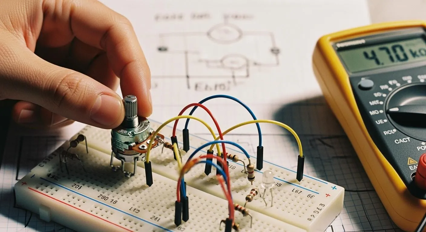
If you want to know how to hook up a potentiometer, you can do it with just a few simple steps. You need a potentiometer, some connecting wires, and a small screwdriver. A multimeter helps you check your connections. Gather these tools before you start. Take your time and follow each step. You will find that setting up a potentiometer is easier than you think!
Key Takeaways
- Identify the three pins of a potentiometer: the middle pin is the wiper, while the outer pins are fixed ends. This knowledge is crucial for correct wiring.
- Use a multimeter to check connections and ensure proper functionality. Testing helps avoid issues like erratic output or no response.
- Follow a clear wiring process: connect the first pin to power, the third pin to ground, and the middle pin to the component you want to control.
- Adjusting the potentiometer changes the output voltage. This allows for precise control over devices like lights and audio systems.
- Regularly inspect and maintain your potentiometer to prevent issues. Clean connections and check for damage to ensure reliable performance.
Materials & Tools

Before you start wiring your potentiometer, you should know the different potentiometer types and the tools you need. This helps you choose the right component for your circuit diagram and ensures a smooth setup process.
Potentiometer Types
You will find three main potentiometer types: rotary, slide, and trimmer. Each type works best in specific situations. The table below shows their differences and common uses:
| Type | Description | Usage Examples |
|---|---|---|
| Slide Potentiometer | Adjusts resistance by moving a wiper along a straight track. | Audio mixing consoles |
| Trimmer Potentiometer | Small adjustable resistor for fine-tuning circuits, usually adjusted infrequently. | Calibration in electronic devices |
| Rotary Potentiometer | Circular resistive element turned by a shaft, available in single-turn and multi-turn. | Volume controls, position sensors |
Rotary potentiometers come in single-turn and multi-turn versions. You use single-turn models for simple adjustments, like volume controls. Multi-turn models give you more precision, which is important for fine-tuning in sensitive circuits. Slide potentiometers work well when you need smooth, linear control, such as in audio equipment. Trimmer potentiometers are best for calibration tasks, where you set the resistance once and rarely change it.
When you select a potentiometer, consider the performance and reliability you need. Factors like linearity, resolution, and repeatability affect how well your circuit works. For high-precision applications, conductive plastic potentiometers offer better accuracy and longer life than wire-wound types.
Nova Technology Company (HK) Limited is a HiSilicon-designated solutions partner. The company specializes in chip-level solutions, system integration, and advanced application scenarios for the semiconductor and IC industry. You can rely on their expertise for professional support in potentiometer selection and integration.
Tools Needed
You need a few basic tools to wire a potentiometer safely and accurately:
- Small screwdriver (for tightening terminals)
- Connecting wires
- Wire stripper or cutter
- Multimeter (for checking connections)
- Soldering iron (optional, for permanent wiring)
Always turn off power before wiring or adjusting components. Make sure your hands are dry and all connections are secure before you power up your circuit. Use a low voltage DC supply to prevent damage and avoid short circuits by checking wire insulation.
With the right potentiometer and tools, you can set up your circuit diagram with confidence and achieve reliable results.
How to Hook Up a Potentiometer

Setting up a potentiometer in your circuit can seem tricky at first, but you can master it by following a clear process. This section will guide you through identifying the pins, wiring the potentiometer, and testing the output. You will also see wiring examples and learn how to read the wiper output for adjusting resistance.
Identify Terminals
Before you start with potentiometer wiring, you need to identify the three pins. Each pin has a specific function in the circuit. Here is how you can do it:
- Hold the potentiometer so the pins face you. Rotary potentiometers usually have pins in a semi-circle, while slide potentiometers have pins in a straight line.
- The middle pin is almost always the wiper. The two outer pins are the fixed ends.
- Look for small numbers or labels next to the pins. These markings help you match the pinout to a wiring diagram or circuit diagrams.
- If you want to confirm the pins, use a multimeter. Remove the potentiometer from the circuit and turn off all power. Set your multimeter to resistance mode. Measure between the two outer pins to find the total resistance. Then, measure between the middle pin and each outer pin while turning the knob. The resistance should change as you move the wiper.
Tip: Always check the datasheet for your potentiometer model. The datasheet gives you the exact pinout and helps you avoid wiring errors.
Wiring Steps
Now that you have identified the pins, you can start wiring the potentiometer. Follow these steps for a standard setup:
- Gather your potentiometer, wires, a power source (like a battery), and the component you want to control (such as an LED or motor).
- Connect the first pin (Terminal 1) to the positive side of your power supply.
- Connect the third pin (Terminal 3) to the ground (GND) of your power supply. This step is often called connecting the third pin.
- Attach the middle pin (Terminal 2), which is the wiper, to the input of the component you want to control. This is where you read the variable output.
- Double-check your connections with a wiring diagram or circuit diagrams to make sure everything matches.
- If you want a permanent setup, you can solder the wires to the pins. For temporary setups, use jumper wires.
Here is a table with wiring examples for different potentiometer types:
| Potentiometer Type | Example Part | Typical Application |
|---|---|---|
| Linear Taper Potentiometer | Bourns PTV09A | Lighting dimmers, motion sensors |
| Logarithmic Taper | ALPS RK09K | Volume controls in audio equipment |
| Rotary Potentiometer | TT Electronics P160KN | Dashboard controls, audio mixers |
| Slide Potentiometer | N/A | Graphic equalizers, audio faders |
| Multi-Turn Potentiometer | N/A | Precision measurement systems |
| Trimmer Potentiometer | N/A | Calibration in sensitive devices |
Note: Always connect the third pin to ground to ensure proper operation. If you reverse the power and ground pins, the potentiometer will still work, but the direction of adjustment will be opposite.
Testing Output
After you finish wiring, you need to test the output to make sure the potentiometer works as expected. Follow these steps:
- Gather a DC power supply, a voltmeter, and jumper wires.
- Connect the negative terminal of the power supply to the ground pin of the potentiometer.
- Attach the positive terminal of the power supply to the first pin.
- Connect the positive lead of the voltmeter to the wiper (middle pin).
- Connect the negative lead of the voltmeter to the ground.
- Set the voltmeter to measure DC voltage. Set the power supply to a safe voltage, such as 10 volts DC.
- Turn the potentiometer knob or slide the control. Watch the voltmeter reading. When the potentiometer is fully turned one way, the output should read close to 0 volts. When fully turned the other way, it should read close to the supply voltage.
- If the output does not change smoothly, check your wiring and make sure you followed the wiring diagram.
Tip: Always use a current-limiting resistor if you connect the potentiometer to sensitive components. This prevents damage from accidental short circuits.
By following these steps, you will understand how to hook up a potentiometer, identify the pins, and test the output. You can use this process for many wiring examples and circuit diagrams. Whether you are connecting the third pin for a simple LED dimmer or building a more complex system, these steps will help you achieve reliable potentiometer wiring.
Adjustment & Use
Adjusting Resistance
You can adjust the resistance of a potentiometer by turning its knob or sliding its control. This action moves the wiper along the resistive track. As you move the wiper, the output voltage changes. When you set the wiper near the middle, the output voltage usually sits around half of the supply voltage. If you move the wiper toward one end, the output voltage shifts closer to that end’s value.
Potentiometers come in many resistance values. The most common types use the E12 or E24 series, which offer increments for fine-tuning. Here is a table showing how these series work:
| E-Series | Increments per Decade | Spacing Between Values |
|---|---|---|
| E12 | 12 | ~20% |
| E24 | 24 | ~10% |
You often find carbon film potentiometers in electronics. These are cost-effective and work well for most basic adjustments. However, their resistance can change with temperature or moisture, so use them in dry, stable environments.
To measure the resistance accurately, you can use a multimeter. For more precise adjustments, trimmer potentiometers help you set reference voltages on circuit boards. You can also add a small capacitor from the wiper to ground to filter out noise.
Tip: Always check the impedance and tolerance of your adjustable resistor to ensure reliable performance in your circuit.
Common Applications
You will see potentiometers in many devices. In consumer electronics, you use a potentiometer as volume control in radios, speakers, and music players. You can also adjust led brightness in lamps and displays. In household appliances, potentiometers help set oven temperatures, fan speeds, and timer settings.
In industrial automation, potentiometers serve as input devices for human-machine interfaces. Operators use them to adjust pressure, temperature, and flow rates. This precise control keeps machines running smoothly and safely.
Modern smart potentiometers combine analog and digital features. You can program them for remote adjustments and connect them to microcontrollers for automation. These advanced types offer self-calibration and error detection, which improve reliability and extend lifespan.
The resistance curve of a potentiometer affects how you control sound or light. Higher resistance values give you a wider range for fine-tuning. The type of potentiometer—linear or audio taper—changes how sensitive the control feels, which is important for audio and lighting effects.
Potentiometers play a key role in both simple and advanced circuits. You can use them to adjust, calibrate, and control many electronic functions with ease.
Troubleshooting
When you set up a potentiometer, you may encounter issues that prevent it from working as expected. Troubleshooting helps you identify wiring errors and fix problems quickly. You can avoid damage and ensure proper setup by following best practices.
Wiring Errors
Incorrect potentiometer wiring often leads to symptoms such as erratic output, no response, or noise. You should check the pins and connections before powering up your circuit. The table below shows common wiring errors, their causes, and solutions:
| Wiring Error Type | Causes | How to Fix | How to Avoid |
|---|---|---|---|
| Erratic Output / Jumping | Loose wire connections, cold solder joints, internal oxidation | Repair solder joints, clean contacts, or replace the potentiometer | Use sealed potentiometers in dusty areas |
| No Output or Full Volume/Speed Only | Open circuits, wrong wire connections, short circuits | Visually check for shorts, ensure correct wiring per diagram | Verify terminal connections before soldering |
| Output Stuck at Half Value / Non-functional | Disconnected wiper terminal, floating ground | Ensure all terminals are properly soldered | Perform continuity tests before powering up |
| Noise / Crackling | Dirty connections, poor grounding, EMI interference | Clean with contact cleaner, re-solder joints, use shielded cabling | Use high-quality shielded cables and ensure strong chassis grounding |
You may notice symptoms like output stuck at half value, crackling sounds, or jumping readings. These problems usually result from miswired pins, dirty contacts, or poor grounding. Always check your wiring diagram and confirm the pin connections.
Tip: Use a multimeter to test resistance between pins. Rotate the shaft and observe changes. The resistance should change smoothly without jumping.
Fixing Issues
If your potentiometer does not adjust resistance or seems unresponsive, follow these steps:
- Inspect the potentiometer for physical damage or broken pins.
- Use a multimeter to check for poor contact or continuous closure.
- Replace damaged components or scrape oxidized contacts to restore functionality.
- If the spring force is weak, replace the potentiometer spring.
- Disassemble the potentiometer and clean the carbon film if you see wear.
You can prevent damage by following these best practices:
- Tin solder joints before soldering to remove paint and dirt.
- Make sure the potentiometer mark is visible during installation.
- Install adjustable potentiometers in accessible locations.
- Secure the potentiometer firmly to prevent loosening or collision with other components.
- Use appropriately sized knobs to avoid excessive torque and damage to the internal stop.
- Avoid forcefully bending or twisting pin-type leads.
- Limit welding time and avoid prolonged heating to prevent deformation around the pins.
Regular inspection helps maintain performance. Clean dust and debris from the potentiometer and check for loose connections. In harsh environments, use sealed potentiometers and shielded cables. Monitor for unusual noise or vibration and test the full travel range of the shaft.
Note: Always select the correct resistance value for your application. Avoid overloading the track and follow manufacturer guidelines for wiper current.
By checking your wiring diagram, confirming pin connections, and following these steps, you can fix most potentiometer wiring issues and keep your circuit running smoothly.
You can set up a potentiometer with confidence by following a few simple steps. Start by identifying the pins, connect the terminals as needed, and test the output. This process gives you hands-on control over devices like lights and audio systems.
- Potentiometers let you adjust resistance easily, offering precise control and immediate feedback.
- You can use them in many applications because they come in different shapes and sizes.
Try wiring a potentiometer yourself. You will see how practical and rewarding it is to control your own electronic projects!
FAQ
How do you know which potentiometer to choose?
You should check the resistance value and power rating for your project. Rotary potentiometers work well for most adjustments. Slide types fit audio equipment. Trimmer potentiometers help with calibration. Always match the potentiometer to your circuit’s needs.
Can you use a potentiometer to control LED brightness?
Yes, you can use a potentiometer to adjust LED brightness. Connect the wiper to the LED circuit. As you turn the knob, you change the voltage and control the light level. This method works best with low-power LEDs.
Why does my potentiometer not change the output?
You may have a wiring issue or a damaged potentiometer. Check all connections and make sure you connect the wiper correctly. Use a multimeter to test resistance. Replace the potentiometer if it still does not work.
Is it safe to solder potentiometer terminals?
You can solder the terminals for a permanent connection. Use a low-wattage soldering iron and work quickly. Avoid overheating the pins. Let the potentiometer cool before testing your circuit.
Can you use a potentiometer with a microcontroller?
Yes, you can connect a potentiometer to a microcontroller’s analog input. The microcontroller reads the voltage from the wiper. You can use this setup for volume, position, or light controls in your projects.


