

0347910181 Datasheet and Pinout: Specs for Design and Sourcing
0347910181 datasheet essentials, pinout overview, key specs, and design/sourcing checks for engineers and buyers. Request a quote on IC-Online.
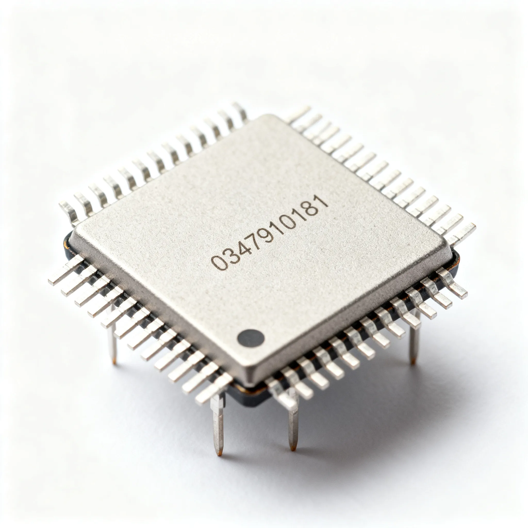
Why the 0347910181 Micro-Fit 3.0 Housing Demands a Second Look at the Datasheet
At first glance, a 2-circuit nylon connector housing looks like the simplest component on your BOM. But the 0347910181 Micro-Fit 3.0 receptacle from Molex has tripped up more than a few experienced power-distribution designers. The dual-row panel-mount footprint, with its snap-fit ears and seemingly straightforward pin numbering, hides orientation rules that are easy to misinterpret until you're staring at a first-article failure.
The most common mistake? Assuming pin 1 sits on the left when the locking tab faces up. In practice, the 0347910181 datasheet defines pin 1 orientation relative to the polarizing rib and the embossed cavity number on the housing bottom—not the tab alone. Get this wrong early in layout, and your board-level connector will mate backward, forcing a costly respin or a field-rework nightmare.
A structured datasheet walkthrough, much like the detailed TL071 datasheet and pinout guide demonstrates for precision op-amps, prevents these first-article failures. Just as that guide walks engineers through offset null pins and phase-reversal behavior that a casual scan misses, the 0347910181 documentation demands a careful reading of current derating curves, terminal compatibility matrices, and the panel cutout tolerance stack. Molex publishes these details across multiple documents—the product drawing, the application specification, and the terminal qualification report—and missing any one of them can leave a design vulnerable.
For procurement buyers, the same principle applies. The 0347910181 housing is not a commodity interchangeable with any other 3.00 mm-pitch insulator. Counterfeit housings with incorrect pitch, brittle nylon blends, and missing mold-cavity markings have surfaced at non-franchised distributors. A disciplined review of the official datasheet—cross-referenced against the physical part—is your first line of defense against a batch of housings that crack during terminal insertion or dislodge under vibration.
Key Takeaway: The 0347910181 datasheet is not a single-page drawing. It's a system of documents covering the housing, the terminal (43030 series), and the application specification. Treating it as a unified reference—rather than skimming the pin count and pitch—is the difference between a clean design release and a respin.
Decoding the 0347910181 Pinout and Electrical Specs That Matter for Your Board
The 2-circuit receptacle isn't just a plastic shell—its datasheet defines the pin mapping relative to the locking tab, the maximum contact resistance you can expect after environmental aging, and the current rating that drops significantly when both circuits are energized simultaneously. Relying on the headline "8.5 A per contact" figure without reading the derating footnotes is a classic trap.
Here's what the Molex product specification actually tells you. The 0347910181 uses the Micro-Fit 3.0 terminal system, where the receptacle housing accepts male crimp pins (Molex series 43030). The mating plug housing (e.g., 043025 series) carries female crimp sockets. This gender convention—receptacle = male pins, plug = female sockets—is opposite to what some engineers expect from D-sub or circular connector experience, and it's worth double-checking during schematic symbol creation.
Pin 1 orientation is defined by the triangular polarizing rib on the housing face. When you hold the 0347910181 with the panel-mount ears facing you and the locking tab upward, pin 1 is on the left. The embossed cavity number on the bottom surface provides a secondary visual reference. The pitch is 3.00 mm, and the dual-row layout stacks the two circuits in a single column, keeping the housing footprint compact for space-constrained power entry points.
The table below consolidates the key electrical and mechanical parameters engineers need during schematic capture and PCB layout. These values come from the Molex product drawing and application specification—always verify against the latest revision before freezing your design.
| Parameter | Value/Range | Unit/Notes |
|---|---|---|
| Pitch | 3.00 | mm, center-to-center |
| Circuit count | 2 | Single row, dual position |
| Contact resistance (max) | 10 | mΩ, initial; may increase after environmental cycling |
| Current rating (per contact, free air) | 8.5 | A, with 18 AWG wire, single circuit energized |
| Current rating (all circuits loaded, 30°C) | 6.5 | A per circuit, derated per UL testing |
| Voltage rating (max) | 600 | V AC/DC, application-dependent |
| Dielectric withstanding voltage | 1,500 | V AC for 1 minute |
| Insulation resistance (min) | 1,000 | MΩ at 500 V DC |
| Operating temperature range | -40 to +105 | °C, housing and terminal system |
| Housing material | Nylon 6/6, UL 94V-0 | Black, non-glossy finish |
| Mating terminal series | 43030 (male crimp) | Micro-Fit 3.0 male crimp terminal only |
| Wire gauge range | 20–24 | AWG, verify with terminal datasheet |
Tip: The 6.5 A derated figure assumes a 30°C ambient and all circuits energized. If your application operates in a 60°C enclosure, request the temperature-rise curve from the official Molex application specification—the derating is steeper than a linear interpolation would suggest. Many engineers spec a 5 A per-circuit ceiling as a conservative design rule for the 0347910181 in enclosed, fan-less systems.
Contact resistance is another parameter that deserves scrutiny. The 10 mΩ maximum is an initial value measured on virgin terminals. After 100 mate/demate cycles and exposure to mixed flowing gas (MFG) testing that simulates industrial environments, contact resistance can drift upward. For applications where voltage drop across the connector is critical—such as 3.3 V or 5 V power rails with tight tolerance budgets—factor in a 15–20 mΩ end-of-life contact resistance when calculating IR drop.
0347910181 vs. Other Micro-Fit 3.0 Housings: Selecting the Right Circuit Count and Mounting Style
The 0347910181 gives you a 2-circuit, panel-mount receptacle with snap-fit ears. But Molex's Micro-Fit 3.0 ecosystem spans dozens of housing variants—different circuit counts, mounting styles, and gender configurations—all sharing the same terminal system. Choosing the wrong housing for your mechanical constraints can force a bracket redesign or a last-minute BOM change that procurement wasn't expecting.
For multi-source evaluations, the approach documented in the LM358 multi-vendor datasheet comparison offers a useful mental model: just as engineers cross-reference op-amp specs across TI, ST, and Onsemi variants to spot offset voltage shifts, connector selection requires comparing panel cutout dimensions, retention force, and terminal compatibility across different housing part numbers—even within the same manufacturer's portfolio.
The table below compares the 0347910181 against three other Micro-Fit 3.0 housings that might appear on the same BOM. Each serves a different mechanical role, and mixing them up can lead to assembly-line stoppages.
| Comparison Metric | 0347910181 (Reference) | 0347910104 (4-Circuit Receptacle) | 0430250200 (2-Circuit Plug) | Selection Criteria & Failure Boundary |
|---|---|---|---|---|
| Circuit count | 2 | 4 | 2 | Match to conductor count; over-specifying adds cost and panel real estate |
| Gender | Receptacle (accepts male pins) | Receptacle | Plug (accepts female sockets) | Verify mating partner; plug/receptacle mismatch is the #1 BOM error |
| Panel mount | Yes, with snap-fit ears | No (free-hanging or PCB-mount variant) | No (free-hanging) | Ears provide mechanical retention; omit them only if the connector is board-mounted |
| Panel cutout | 7.90 × 5.80 mm | N/A (no ears) | N/A (no ears) | Cutout tolerance ±0.05 mm; oversized cutouts lose retention force |
| Terminal series | 43030 (male crimp) | 43030 (male crimp) | 43031 (female crimp) | Cross-check terminal gender before ordering reels; terminals are not interchangeable between plug and receptacle |
What's not obvious from the part-number matrix alone is that the 4-circuit 0347910104 drops the panel-mount ears entirely. If your design uses a bulkhead feed-through and you spec the 0347910104 by mistake, you'll have no mechanical retention beyond the mating force of the plug. In a vibration-heavy environment—think industrial motor drives or portable medical equipment—that missing retention can lead to intermittent disconnects that are maddeningly difficult to diagnose.
The 12-circuit 0430251200 plug housing, meanwhile, is a different beast entirely. It uses the same 3.00 mm pitch and terminal system, but the housing is longer, the insertion force is higher, and the mating alignment tolerances are tighter. When you're building a cable assembly that mates with a 0347910181 panel-mount receptacle, the 2-circuit 0430250200 plug is the correct mating partner—not a higher-circuit-count variant adapted with unused positions. Unused circuits in a Micro-Fit 3.0 housing create creepage paths that can degrade the voltage rating, especially at altitudes above 2,000 meters where the Paschen curve shifts.
Procurement Note: When sourcing multiple Micro-Fit 3.0 housings on the same BOM, confirm that your distributor can supply the correct terminal series for each housing gender. The 43030 (male) and 43031 (female) terminals are often stocked separately, and a terminal shortage can hold up the entire connector build even if the housings are on the shelf.
Design and Sourcing Rules for 0347910181: From Crimp Terminals to Panel Cutouts
Don't treat the 0347910181 housing as a standalone buy. The housing is just one piece of a three-part system: the insulator, the male crimp terminal (Molex 43030 series), and the mating plug assembly. Each component has its own datasheet, and the design rules span all three documents. As the L298N datasheet explainer demonstrates for motor drivers—where missing a pin's functional context can cascade into board-level failures—the same logic applies here: the panel cutout, the wire gauge, the insulation diameter, and the crimp tooling are all interdependent parameters that cannot be specified in isolation.
Below is a design-rule reference table that consolidates the mechanical and sourcing parameters engineers and buyers need to verify before committing to production volumes.
| Design Parameter | Recommendation | Verification Method |
|---|---|---|
| Mating terminal | Molex 43030-0001 or 43030-0007 (phosphor bronze, gold flash) | Cross-check the terminal drawing against the housing product specification PS-43030-001 |
| Wire gauge | 20–24 AWG stranded, 7-strand minimum | Verify the conductor OD against the terminal crimp barrel ID; 24 AWG with thin-wall insulation may require a smaller crimp die |
| Insulation diameter | 1.80–2.60 mm | Measure with a caliper on the actual wire sample; exceeding 2.60 mm prevents full terminal insertion into the housing cavity |
| Panel cutout | 7.90 × 5.80 mm, ±0.05 mm tolerance | Request a first-article panel sample and test the snap-fit retention force; should withstand 30 N minimum pull force |
| Panel thickness | 0.80–1.60 mm | Thicker panels may prevent the ears from fully engaging; thinner panels reduce retention force below spec |
| Crimp tooling | Molex 63811-1000 (hand tool) or 63801-9800 (applicator) | Verify crimp height (0.90–1.10 mm for 20 AWG) with a crimp micrometer; pull-test at 5 N minimum |
| Creepage distance | 3.20 mm minimum between adjacent circuits | Measure on the assembled housing; this is built into the housing design but verify no flash or molding defects reduce it |
| Mating cycles | 30 cycles minimum (tin), 100 cycles (gold) | Lifecycle test per EIA-364-09; contact resistance measured before and after cycling |
Tip: The insulation diameter range (1.80–2.60 mm) is just as critical as the wire gauge. We've seen field failures where 20 AWG wire with an oversized silicone jacket—common in high-temperature applications—exceeded the 2.60 mm upper limit and prevented the terminal from fully seating in the 0347910181 housing. The terminal latch engages, but the pin doesn't bottom out, leaving a 0.5 mm gap that causes intermittent contact when the assembly vibrates. Always measure the actual insulation OD on your production wire sample, not just the nominal spec from the wire datasheet.
For procurement teams, the sourcing checklist below translates these design rules into actionable RFQ requirements:
- Request the complete document package: product drawing (987650-series), application specification (AS-43030-001), and the terminal qualification test report (for the specific 43030 variant you're buying).
- Verify the crimp terminal plating: gold flash (0.38 µm Au over 1.27 µm Ni) is the standard for the
0347910181mating system; tin plating is available but verify the mating cycle requirement—tin degrades faster under vibration. - Confirm the panel cutout tolerance stack: if your enclosure is sheet metal with a stamped cutout, the ±0.05 mm housing tolerance adds to the stamping tolerance. Request a fit-check with actual production panels, not laser-cut prototypes.
- Check the terminal material: phosphor bronze (C51000) offers better spring retention than brass (C26000) in high-temperature applications above 85°C. If your design operates near the 105°C upper limit, specify phosphor bronze terminals explicitly.
- Validate the wire seal compatibility: if your application requires an IP67 rating, the standard
0347910181housing is not sealed. Molex offers a sealed Micro-Fit 3.0 variant (different part number); verify with your distributor whether a sealed option exists for your circuit count.
0347910181 Sourcing and Design: Questions Engineers Ask Before Buying
Senior engineers and procurement leads don't just want the datasheet numbers—they want the real-world current capacity, the approved terminal alternatives, and a reliable way to verify the housing's authenticity before committing to a production reel. Below are the six questions we hear most often during pre-production reviews.
Q: What is the actual maximum current per contact in a 0347910181 housing when both circuits are loaded?
The terminal system—the Micro-Fit 3.0 male crimp terminal (Molex 43030 series)—is rated up to 8.5 A per contact in free air with a single circuit energized. But Molex derates the 0347910181 housing to 6.5 A per circuit when all positions are energized simultaneously at 30°C ambient. This derating accounts for the mutual heating effect of adjacent current-carrying contacts in the compact 3.00 mm pitch housing. Above 30°C, the current capacity drops further—consult the temperature rise curve in the official Molex application specification (AS-43030-001). As a conservative design rule, limit continuous current to 5.0 A per circuit in enclosed, fan-less enclosures operating at 60°C internal ambient.
Q: Can I use 0347910181 with standard 0.093-inch pin terminals instead of Micro-Fit 3.0?
No. The 0347910181 housing is engineered exclusively for Micro-Fit 3.0 male crimp terminals (Molex series 43030). The contact footprint, locking lance geometry, and 3.00 mm pitch are incompatible with standard 0.093-inch (2.36 mm pitch) or other series terminals. Forcing a mismatched terminal into the housing cavity will damage the locking lance, deform the housing wall, and lead to intermittent connections that may pass initial continuity testing but fail under thermal cycling or vibration. If you're migrating from a 0.093-inch connector system, redesign the entire connector interface—do not attempt a terminal swap.
Q: What is the correct panel cutout for the 0347910181 with ears, and how much tolerance is allowed?
The recommended panel cutout for the 0347910181 is 7.90 mm × 5.80 mm, with a tolerance of ±0.05 mm. This tolerance ensures the snap-fit ears engage securely without stressing the housing bridge between the ears. Oversizing the cutout—even by 0.15 mm—can reduce retention force below the 30 N minimum specified in the product drawing, causing the connector to dislodge under vibration. For sheet metal panels, the stamped edge condition (burr height, rollover) can further reduce effective retention; specify a deburred cutout and test retention force on production-representative panel samples, not laser-cut prototypes with smooth edges.
Q: How can I verify the authenticity of 0347910181 housings when sourcing from non-franchised distributors?
Check four physical markers against the official Molex datasheet. First, locate the mold cavity number embossed on the bottom surface of the housing—legitimate 0347910181 parts always carry this marking. Second, examine the surface finish: Molex Nylon 6/6 has a matte, non-glossy black appearance; counterfeit housings often use a shinier, lower-grade nylon blend that becomes brittle at low temperatures. Third, verify the embossed Molex logo on the housing face—counterfeits may omit it, use a different font, or place it incorrectly. Fourth, measure the pitch between the two circuit positions with a caliper: it should be exactly 3.00 mm. Counterfeit housings frequently exhibit a pitch error greater than 0.05 mm, which causes misalignment with the mating plug and can damage terminals during insertion. For production volumes, require a Certificate of Conformance (CoC) traceable to Molex's authorized distribution chain.
Q: Is there an approved second-source for the 0347910181 housing or its terminals?
Molex does not license the Micro-Fit 3.0 housing design, so there is no authorized second-source manufacturer for the 0347910181 insulator. For the crimp terminals (43030 series), Molex-approved alternatives may exist from listed preferred suppliers, but always verify the terminal material (phosphor bronze C51000 or brass C26000), the plating thickness (gold flash: 0.38 µm Au minimum over 1.27 µm Ni), and the crimp barrel dimensions against the latest Molex product specification PS-43030-001. Using a non-approved terminal that appears mechanically compatible but has a different locking lance geometry or spring rate can result in terminal back-out during mating. Verify single-source risk for the housing as part of your BOM risk assessment, and confirm lead-time and allocation with your franchised distributor before committing to a production schedule.
Q: What revisions should I look for when downloading the 0347910181 datasheet to ensure I have the latest specs?
Use the Molex part number search on molex.com or a trusted aggregator like ALLDATASHEET.COM. The latest revision is typically indicated by a letter suffix in the document number (e.g., 987650-XXXX) and a revision date code on the first page. Two specific parameters were updated in recent revisions and are worth cross-checking: the recommended panel cutout dimensions (tightened from ±0.10 mm to ±0.05 mm) and the current derating curves (updated to reflect new UL 1977 test conditions for connector current ratings). If your datasheet doesn't show the temperature rise curve with both circuits loaded, you're looking at an older revision. Download the latest version directly from Molex or request it through your franchised distributor to ensure your design reflects the current qualification data.
References & Further Reading
- TL071: Detailed Datasheet, Pinout, and Alternatives Guide — Utmel
- ALLDATASHEET.COM — Electronic Parts Datasheet Search
- L298N Datasheet Explained: Pinout, Specifications, and Motor Control Basics — Ultra Librarian
- LM358 Datasheet: Multi-Vendor Specifications, Pinout, and Applications — ERSA Electronics
- Molex Official Website — Part Number Search and Product Specifications
- Connectors Category — IC-Online
- IC-Online — Electronic Component Sourcing and RFQ Platform
Getting the 0347910181 Micro-Fit 3.0 housing right—from the pinout orientation to the panel cutout tolerance to the terminal plating specification—is a design discipline that pays for itself in avoided respins and field failures. The datasheet is your primary reference, but it's not a single document; it's a system of interrelated specifications that span the housing, the terminal, and the application environment. When you're ready to move from design review to production sourcing, the next step is confirming current availability, allocation, and pricing with a distributor who can provide traceable, authentic Molex product.
Request a quote or upload your BOM via IC-Online. Our platform handles mixed BOMs with flexible MOQ, and our procurement specialists can verify terminal compatibility, confirm panel cutout dimensions against the latest datasheet revision, and help you secure allocation-backed supply for the 0347910181
Related Articles
 Blog
BlogMBR30150CT Supply Risk Assessment: What to Ask Before You Buy
Assess MBR30150CT sourcing risks before you buy. RFQ questions on traceability, date codes, testing, alternatives, and supply continuity for procurement teams.
 Blog
Blog776230-1 Datasheet and Pinout: Specs for Design and Sourcing
776230-1 datasheet essentials, pinout overview, key specs, and design/sourcing checks for engineers and buyers. Request a quote on IC-Online.
 Blog
BlogHow VSC Works in Modern Cars and Why It Matters
What is VSC on a car? VSC (Vehicle Stability Control) is an electronic system that brakes individual wheels and cuts engine power to maintain traction. The VSC light indicates active intervention or a fault.
 Blog
Blog2SA1213 Obsolescence Risk Checklist: Confirm Lifecycle Status Before Sourcing
2SA1213 lifecycle and obsolescence risk checklist. What to verify before redesign or last-time-buy — without assuming drop-in replacements.
 Blog
BlogExcess Inventory: How Component Engineers Can Turn Surplus into Supply Chain Resilience
Practical guide for buyers and engineers: Excess Inventory: How Component Engineers Can Turn Surplus into Supply Chain Resilience. Sourcing, risk, and selection notes.
 Blog
BlogUnderstanding How Graphics Cards Work in Ordinary Electronics
A definition graphics card explains how this hardware turns data into images for your screen. It's crucial for video calls, streaming, and light gaming on daily devices.