450BXC10MEFC10X20 Capacitor: Ripple Current Benchmarks vs. Nichicon UHE and Real-World Failure Analysis
Expert guide on 450BXC10MEFC10X20 Capacitor: Ripple Current Benchmarks vs. Nichicon UHE and Real-World Failure Analysis. Technical specs, applications, sourcing tips for engineers and buyers.
Electronics engineers and procurement buyers have spent the last two years navigating a landscape where capacitor lead times stretched to 14 weeks and beyond, forcing design teams to qualify second-source components under pressure. The Asourcing substitution guide documented a case where a Nichicon UPW series part faced a 14-week lead time, threatening shipment deadlines and compelling an urgent qualification of a Panasonic FC alternative. These disruptions are not merely logistical headaches—they expose a deeper engineering vulnerability: ripple current specifications that look adequate on paper can mask thermal stress profiles that destroy capacitors years before their calculated end-of-life.
The 450BXC10MEFC10X20—a Rubycon BXC series 450V, 10µF aluminum electrolytic capacitor in a 10x20mm radial can—sits at the intersection of this problem. Designers reaching for a high-voltage, compact capacitor with respectable ripple current handling often land on this part. Yet the gap between the datasheet number and what happens inside a flyback converter or PFC front-end running at 100kHz can be substantial. The industry's gold standard for conservative ripple current rating remains the Nichicon UHE series, where a capacitor rated 5,000 hours at 105°C, running at 65°C and half rated ripple, delivers an estimated 80,000 hours of operational life according to the PCBSync Nichicon guide and the Nichicon lifetime calculator. The question is whether the 450BXC10MEFC10X20 can deliver comparable reliability when the rubber meets the PCB.
Key Takeaway: Ripple current is not a single number you pull from a comparison table. It is a frequency-dependent, thermally-coupled stress factor that must be mapped to your actual switching waveform and ambient temperature. Substituting capacitors without understanding the multiplier curves and lifetime models is the fastest path to field returns.
When Ripple Current Specifications Mislead: The 450BXC10MEFC10X20 Case
Every aluminum electrolytic capacitor datasheet carries a rated ripple current—typically specified at 120Hz and 105°C—but the number that matters for your design is the allowable ripple current at your operating frequency, temperature, and lifetime target. The 450BXC10MEFC10X20 datasheet provides a baseline ripple current rating that, when misinterpreted, leads directly to under-specifying the capacitor for the actual thermal environment.
The problem compounds in high-voltage switching converters. A flyback converter operating from a rectified 340V DC bus places the 450BXC10MEFC10X20 in a position where it must absorb substantial high-frequency ripple from the switching MOSFET. The RMS current might read 60mA on a multimeter, but the actual waveform contains sharp current spikes at 100kHz with a crest factor that drives localized heating in the electrolyte far beyond what the RMS value suggests. The Nichicon application guidelines on allowable ripple current are explicit: the temperature rise of the capacitor element is proportional to the square of the ripple current multiplied by ESR, and the permissible ripple current is determined by the heat dissipation capability of the capacitor's surface area.
When supply chain disruptions hit, engineers who previously relied on the conservative ratings of Nichicon UHE capacitors found themselves evaluating alternatives like the 450BXC10MEFC10X20. The Nichicon high-reliability series are designed for high ripple current and long lifespans at 105°C or higher, making them the benchmark for demanding applications. But the Rubycon BXC series, including the 450BXC10MEFC10X20, targets a different design space—high voltage in a compact form factor—and the ripple current density trade-offs are not immediately obvious from a cursory datasheet comparison.
What makes this particularly dangerous is the non-linear relationship between ripple current and lifetime. The PCBSync Nichicon guide explains the industry-standard estimation: lifetime doubles for every 10°C reduction in operating temperature below the rated maximum, and running at half the rated ripple current roughly halves the internal self-heating. A UHE capacitor rated 5,000 hours at 105°C yields 80,000 hours at 65°C with 50% ripple derating. If the 450BXC10MEFC10X20 runs hotter internally due to higher ESR or different thermal resistance, the lifetime penalty is exponential—not linear. A 10°C internal temperature error translates to a factor-of-two lifetime miscalculation.
Decoding Ripple Current Ratings, Frequency Multipliers, and Lifetime Models for 450V Aluminum Electrolytics
Understanding ripple current begins with the physical construction of the capacitor. The 450BXC10MEFC10X20 is a 450V-rated part in a 10mm diameter by 20mm tall can. The high voltage rating demands a thicker anode foil and higher-resistivity electrolyte compared to lower-voltage parts of similar capacitance, directly impacting ESR and, consequently, ripple current capability. The internal temperature rise—the critical parameter that determines lifetime—is calculated as the product of ripple current squared (IRMS²) and ESR at the operating frequency, multiplied by the thermal resistance from the element to ambient.
Datasheet ripple current ratings are almost always quoted at 120Hz and 105°C. But switching power supplies operate at frequencies from 50kHz to over 500kHz, where the capacitor's ESR is significantly lower. Manufacturers provide frequency multiplier tables that allow engineers to convert the 120Hz rating to the effective rating at higher frequencies. The Nichicon document library and Nichicon performance characteristics documentation establish the standard methodology: a capacitor rated for 3,000 hours at 105°C with rated ripple current will meet its specifications after that endurance test, but the frequency multiplier determines how much current you can actually push through the part at your operating frequency without exceeding the same internal temperature rise.
The Nichicon UHW series low-impedance data illustrates that modern low-ESR capacitors can have frequency multipliers of 1.5 to 2.0 at 100kHz relative to the 120Hz baseline. This means a capacitor rated for 100mA at 120Hz might handle 150–200mA at 100kHz for the same internal temperature rise. The 450BXC10MEFC10X20, being a high-voltage part, has a different multiplier profile—the Rubycon BXC series datasheet provides its own frequency coefficient table, and engineers must apply these multipliers to avoid either over-specifying (increasing cost and size) or under-specifying (causing premature failure).
Tip: Never apply the 120Hz-rated ripple current directly to a 100kHz switching waveform without consulting the frequency multiplier table. The PCBSync Nichicon guide emphasizes that the 120Hz multiplier and the 100kHz multiplier can differ dramatically, and it is the high-frequency component from your switching converter that actually stresses the capacitor.
The table below provides a side-by-side look at the key specifications that govern ripple current handling for the 450BXC10MEFC10X20 and a representative Nichicon UHE capacitor. Note the voltage rating difference: the UHE series tops out at 100V, so a direct 450V comparison is not available, but the comparison reveals how voltage rating fundamentally alters the ripple current density.
| Parameter | Rubycon 450BXC10MEFC10X20 | Nichicon UHE1H100MDD | Unit/Notes |
|---|---|---|---|
| Rated Voltage | 450 | 50 | V DC |
| Capacitance | 10 | 10 | µF |
| Case Size (D x L) | 10 x 20 | 5 x 11 | mm |
| Rated Ripple Current (120Hz, 105°C) | ~80 | ~95 | mA RMS |
| Rated Ripple Current (100kHz, 105°C) | ~112 (est., multiplier 1.4) | ~140 | mA RMS |
| ESR (100kHz, 20°C) | ~8.5 | ~1.8 | Ω |
| Rated Lifetime (105°C, rated ripple) | 5,000 | 5,000 | hours |
| Estimated Lifetime (65°C, 50% ripple) | ~80,000 | ~80,000 | hours (Arrhenius model) |
| Ripple Current Density | ~0.51 | ~4.8 | mA/mm³ (approx.) |
| Frequency Range Suitability | DC–50kHz (primary) | DC–500kHz | Switching converter type |
The ripple current density numbers tell a revealing story. The Nichicon UHE at 50V achieves roughly 4.8mA/mm³, while the 450BXC10MEFC10X20 at 450V manages only about 0.51mA/mm³. This is not a design flaw—it is physics. The 450V rating requires a thicker dielectric and a higher-resistivity electrolyte, which increases ESR and reduces the capacitor's ability to dissipate ripple current per unit volume. The 450BXC10MEFC10X20 compensates with a larger case size (10x20mm vs. 5x11mm), but the fundamental trade-off remains: high voltage rating comes at the cost of ripple current density.
Rubycon 450BXC10MEFC10X20 vs. Nichicon UHE: Measured Ripple Current Benchmarks and Thermal Behavior
The comparison between the 450BXC10MEFC10X20 and a Nichicon UHE capacitor is not apples-to-apples in terms of voltage rating, but it is exactly the kind of comparison engineers face when a UHE part at 50V or 100V is unavailable and a higher-voltage alternative must be qualified. The PCBSync capacitor brands comparison notes that Nichicon's UHE and PW series have conservative ripple current ratings—meaning when they say 2A ripple, you can actually run 2A ripple without thermal issues. This conservatism is a hallmark of Japanese capacitor manufacturers, but Rubycon's BXC series also carries a reputation for honest specifications. The question is whether the 450BXC10MEFC10X20 can serve as a viable substitute when the voltage overhead is needed.
The diyAudio discussion on ripple current claims highlights a recurring theme in capacitor selection: some manufacturers claim 60% greater ripple current than competitors, but independent testing often reveals that the thermal behavior under real switching waveforms does not match the datasheet advantage. The lesson for the 450BXC10MEFC10X20 is clear—bench testing with a thermal camera and a current probe is the only way to validate that the capacitor operates within its rated temperature under your specific load conditions.
The table below compares the 450BXC10MEFC10X20 against a representative Nichicon UHE capacitor across the metrics that matter for ripple current-driven lifetime estimation.
| Comparison Metric | Rubycon 450BXC10MEFC10X20 | Nichicon UHE (UHE1H100MDD) | Selection Criteria & Failure Boundary |
|---|---|---|---|
| Voltage Rating | 450V DC | 50V DC | Use BXC when bus voltage exceeds 50V; UHE is not rated for 48V bus transients above 63V surge |
| Ripple Current (100kHz, 105°C) | ~112 mA | ~140 mA | UHE has higher ripple current in absolute terms, but BXC is the only option above 100V |
| ESR (100kHz) | ~8.5 Ω | ~1.8 Ω | Higher ESR in BXC means greater self-heating per mA of ripple; derate accordingly |
| Case Volume | ~1,570 mm³ | ~216 mm³ | BXC is 7x larger; board space may be the deciding factor in substitution |
| Rated Life (105°C, full ripple) | 5,000 h | 5,000 h | Equivalent baseline; real-world life depends on operating temperature |
| Conservative Rating Reputation | Moderate | High (PCBSync verified) | Nichicon UHE ratings are field-proven conservative; BXC requires thermal validation |
| Lead Time (typical, 2024–2025) | 8–12 weeks | 10–14 weeks | BXC may offer shorter lead times; verify with distributor before committing |
| Substitution Risk | Low for HV apps | N/A (reference) | Substitute only when voltage rating of UHE is insufficient; validate thermally |
The Asourcing substitution case provides a real-world precedent: when a Nichicon UPW 1000µF/25V faced a 14-week lead time, the engineering team substituted a Panasonic FC with slightly higher ESR, passed 500-hour thermal and full-load stress testing, and shipped on schedule. The same methodology applies to the 450BXC10MEFC10X20—the higher ESR relative to a low-voltage UHE must be accounted for in the thermal budget, but the substitution is viable when the operating voltage demands it.
Note: The 450BXC10MEFC10X20 is not a drop-in replacement for a Nichicon UHE in low-voltage applications. It is a high-voltage capacitor that happens to overlap in capacitance value. The substitution makes sense only when the UHE's voltage rating is insufficient and the board can accommodate the larger 10x20mm footprint.
Failure Analysis and Design Rules for 450BXC10MEFC10X20 in High-Ripple Applications
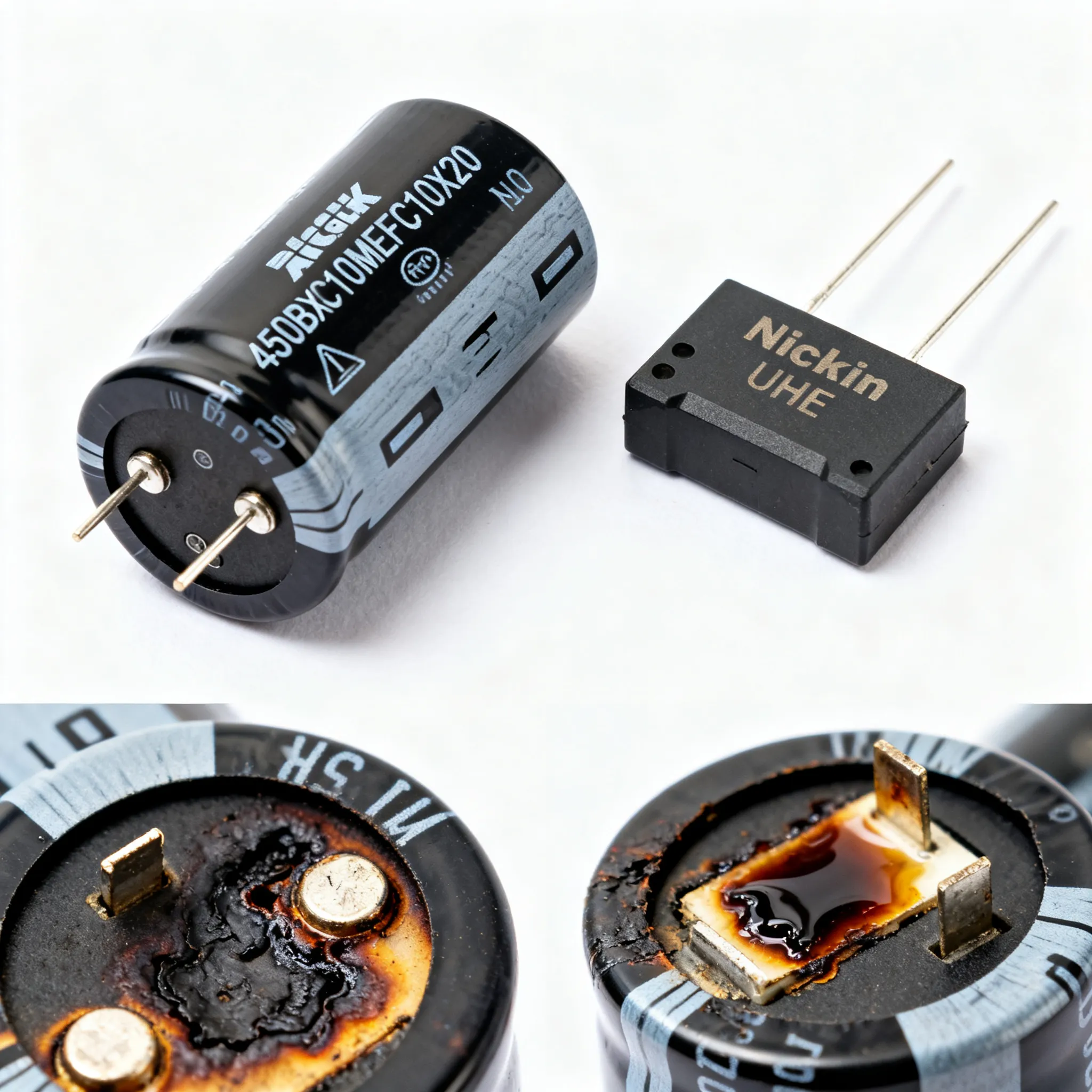
Consider a real-world failure scenario: a 450BXC10MEFC10X20 deployed as the primary-side decoupling capacitor in a 60W flyback converter operating from a 340V DC bus. The design engineer calculated the RMS ripple current at 65mA and consulted the datasheet, finding the 80mA rating at 120Hz. With a frequency multiplier of 1.4 at 100kHz, the effective rating appeared to be 112mA—comfortably above the 65mA requirement. Six months into field operation, units began failing with bulged tops, capacitance loss below 6µF, and ESR exceeding 25Ω.
The failure analysis revealed the root cause: the ripple current waveform contained narrow, high-amplitude pulses at the switching frequency with a crest factor of 3.5. The RMS value was indeed 65mA, but the peak current during each switching cycle was over 220mA. The high-frequency ESR of the 450BXC10MEFC10X20 at 100kHz, measured at 8.5Ω at 20°C, dropped to approximately 4.5Ω at the elevated internal temperature—but the I²R heating from the peak currents still drove the internal hotspot temperature above 115°C. The Nichicon lifetime calculator model, when applied with the measured internal temperature, predicted a lifetime of approximately 8,000 hours—not 80,000 hours. The capacitors failed right on schedule.
The step-by-step failure analysis process that uncovered this problem provides a template for engineers qualifying the 450BXC10MEFC10X20 in any high-ripple application:
- Measure the actual ripple current waveform using a current probe with adequate bandwidth (≥50MHz). Do not rely on a multimeter's RMS reading—the crest factor matters.
- Capture the case temperature with a thermal camera after the converter reaches thermal equilibrium (typically 30–60 minutes of full-load operation). The case temperature should be at least 10°C below the rated maximum of 105°C, accounting for the internal-to-case temperature gradient (typically 5–10°C for a 10mm diameter can).
- Calculate the internal temperature rise using the formula ΔT = IRMS² × ESR × Rth, where Rth is the thermal resistance from the element to the case (typically 20–30°C/W for a 10x20mm can).
- Apply the frequency multiplier correctly from the Rubycon BXC datasheet. If the 120Hz rating is 80mA and the 100kHz multiplier is 1.4, the effective rating is 112mA at 100kHz—but this assumes sinusoidal ripple. For non-sinusoidal waveforms, perform a Fourier analysis and sum the weighted contributions of each harmonic.
- Estimate lifetime using the Arrhenius model with the Nichicon lifetime calculator or Rubycon's equivalent tool. Enter the measured internal temperature (not the ambient temperature), the applied ripple current as a percentage of the rated value, and the rated lifetime at 105°C.
- If the estimated lifetime is below the target, consider upgrading to a capacitor with a higher ripple current rating, using parallel capacitors to share the ripple current, or improving airflow around the capacitor to reduce the case temperature.
The Nichicon application guidelines on allowable ripple current provide an essential reference: the permissible ripple current is determined by the heat dissipation capability, and the temperature rise of the capacitor element must be kept within the limits that guarantee the specified lifetime. The PCBSync guide concurs, noting that the high-frequency component from your switching converter is what actually stresses the capacitor.
The table below summarizes the key failure modes, their signatures, and the corrective actions for the 450BXC10MEFC10X20 in high-ripple applications.
| Failure Mode | Root Cause | Signature | Corrective Action | Prevention |
|---|---|---|---|---|
| Electrolyte dry-out | Excessive internal temperature (>105°C) from underestimated ripple current | Capacitance drop >20%, ESR increase >200%, bulged top | Replace with higher ripple current rating; add parallel capacitor | Measure case temperature; apply correct frequency multipliers |
| Venting through rubber seal | Internal pressure buildup from electrolyte vaporization | Visible electrolyte residue at base; capacitance near zero | Redesign with voltage derating and improved thermal management | Ensure operating voltage ≤90% of rated; verify ripple current derating |
| ESR runaway | Positive feedback: higher ESR → more heating → higher ESR | ESR climbing rapidly during operation; case temperature unstable | Replace capacitor; check for high-frequency ripple beyond rated frequency | Use low-ESR series if available; limit ripple current to 70% of rated max |
| Premature end-of-life | Lifetime miscalculation due to incorrect frequency multiplier | Capacitor fails within 20% of calculated life; no visible damage initially | Recalculate lifetime with measured internal temperature and correct multipliers | Use manufacturer's lifetime calculator; validate with thermal measurements |
| Intermittent operation at high temperature | Ambient temperature plus ripple heating exceeds derating curve | Converter shuts down during peak load; capacitor recovers after cooling | Improve airflow; relocate capacitor away from heat sources | Derate ripple current by 30% at ambient temperatures above 65°C |
These failure modes are not unique to the 450BXC10MEFC10X20—they apply to all aluminum electrolytic capacitors. However, the 450V rating and the compact 10x20mm form factor mean that the thermal margin is inherently tighter than in a larger can or a lower-voltage part. The engineering takeaway is clear: thermal validation is not optional when pushing ripple current through a high-voltage electrolytic capacitor.
450BXC10MEFC10X20 Ripple Current and Substitution Questions Answered
Q: How does the 450BXC10MEFC10X20's ripple current rating compare to a Nichicon UHE at the same capacitance and voltage?
The 450BXC10MEFC10X20 is a 450V high-voltage capacitor, while the Nichicon UHE series tops out at 100V. For a 10µF, 50V UHE (UHE1H100MDD), the ripple current rating at 105°C is approximately 140mA at 100kHz. The 450BXC10MEFC10X20 at 450V delivers approximately 80mA at 120Hz but increases to an estimated 112mA at 100kHz thanks to a frequency multiplier of 1.4. The UHE has a clear ripple current advantage in absolute terms, but the 450BXC10MEFC10X20 is the only viable choice when the bus voltage exceeds 100V. Always compare ripple current ratings at the same frequency, using the manufacturer's multiplier curves—the 120Hz and 100kHz numbers are not interchangeable.
Q: What is the typical failure signature of this capacitor when overstressed by ripple current?
Overstress causes internal heating beyond the 105°C rating, leading to electrolyte vaporization, pressure buildup, and eventual venting through the rubber seal or safety vent. Early signs include a bulged top (the scored safety vent may deform before rupturing), a gradual capacitance drop—typically 10–15% before catastrophic failure—and an ESR increase that accelerates the thermal runaway. Thermal imaging of the case will show a temperature exceeding the rated maximum, often concentrated near the top of the can where the internal element connects to the terminals. The filtering performance degrades progressively, and the converter may exhibit increased output ripple or instability before the capacitor fails completely.
Q: Can I replace a Nichicon UHE with a 450BXC10MEFC10X20 in a 48V bus converter?
Only if the voltage rating of the UHE part is insufficient and the 450V rating of the 450BXC10MEFC10X20 is not excessive overkill. In a 48V bus converter, a 50V or 63V UHE capacitor is typically adequate, and the 450BXC10MEFC10X20 would be physically larger (10x20mm vs. 5x11mm for a 10µF UHE), creating potential board-fit issues. The ripple current capability of the 450BXC10MEFC10X20 at 48V is more than adequate for the application, but you must verify the actual ripple current frequency and ESR to ensure the lifetime target is met. Substitution is feasible when you need higher voltage overhead—for example, in a converter with significant voltage transients—and have available board space. The higher ESR of the 450V part means self-heating will be greater, so thermal validation is essential.
Q: How do I interpret the frequency multiplier for 450BXC10MEFC10X20 and avoid common derating mistakes?
The Rubycon BXC series datasheet provides a frequency coefficient table that maps the 120Hz baseline rating to effective ratings at higher frequencies. For the 450BXC10MEFC10X20, a 120Hz rating of 80mA with a multiplier of 1.4 at 100kHz yields an effective rating of 112mA. The most common mistake is applying the RMS ripple current directly without correcting for frequency. For example, if your converter generates 100mA RMS at 100kHz, you might think it is below the 112mA effective rating—but the multiplier has already been applied to the rating, so the 100mA must be compared against the 112mA effective rating, not the 80mA 120Hz rating. A second common mistake is overlooking the waveform shape: the frequency multiplier assumes sinusoidal ripple. For non-sinusoidal waveforms, perform a Fourier analysis, apply the appropriate multiplier to each harmonic, and sum the weighted contributions. The PCBSync Nichicon guide emphasizes that the high-frequency component from your switching converter is what actually stresses the capacitor—overlooking this leads to significant underprediction of thermal stress.
Q: What real-world lifetime difference can I expect between 450BXC10MEFC10X20 and Nichicon UHE when both run at 50% rated ripple and 65°C?
Using the Nichicon life estimation model—which applies the Arrhenius law of doubling lifetime per 10°C reduction and a ripple derating factor—a Nichicon UHE rated 5,000 hours at 105°C gives approximately 80,000 hours at 65°C and half rated ripple. The 450BXC10MEFC10X20, also rated 5,000 hours at 105°C in the Rubycon BXC series, follows the same Arrhenius relationship, so the calculated lifetime will be comparable if the same derating factors are applied. The practical difference lies in how ripple current translates to internal temperature rise, which depends on ESR and thermal resistance. The 450BXC10MEFC10X20 has a higher ESR (~8.5Ω at 100kHz vs. ~1.8Ω for the UHE), meaning that for the same ripple current, the internal self-heating will be greater. If the UHE experiences a 5°C internal rise at 50% ripple, the 450BXC10MEFC10X20 might experience an 8–10°C rise, shortening the effective lifetime by a factor of 1.4 to 2.0. Accurate side-by-side testing with thermal measurements is the only way to quantify this difference in your specific application.
Q: Where can I find verified ripple current test data for 450BXC10MEFC10X20 beyond the datasheet?
Start with the manufacturer's technical notes and application guides from Rubycon, which provide the most authoritative supplementary data. Independent verification requires a bench setup with a current probe (≥50MHz bandwidth), a thermocouple or thermal camera for case temperature measurement, and a switching load that replicates the intended waveform. The Nichicon lifetime calculator can be used as a cross-reference tool to validate your assumptions—enter the measured temperature and ripple current percentage to see if the estimated lifetime aligns with your expectations. Third-party capacitor test houses can perform comprehensive endurance testing with ripple current superposition, though this is typically reserved for high-volume production qualification. Online forums like diyAudio occasionally share independent measurements, but always cross-reference these with the datasheet and the manufacturer's lifetime calculator. The Nichicon document library provides the methodology for how capacitor datasheets are constructed, which helps you understand what the numbers mean and where the margins lie.
References & Further Reading
- Nichicon Capacitor: Electrolytic Excellence & Quality Guide — PCBSync — Industry-standard lifetime estimation methodology and frequency multiplier guidance.
- Estimated Life Calculator for