

A Simple Definition of GND in Hardware
In electronics, gnd (ground) is the common zero-volt (0V) reference point in a circuit. Think of gnd as the "
In electronics, gnd (ground) is the common zero-volt (0V) reference point in a circuit. Think of gnd as the "floor" of a building. Every voltage measurement is like measuring a height from that floor. This ground reference gives all other voltages in the electronics circuit meaning. The gnd provides a stable point for every voltage measurement.
Improper grounding accounts for a large percentage of damage and malfunction of sensitive electronic equipment.
A proper ground connection is critical for any electronics circuit. It serves three key roles: creating a stable point for voltage measurement, providing a return path for current, and ensuring safety in the circuit. Understanding gnd is essential for reliable electronics projects.
Key Takeaways
- Ground is the zero-volt (0V) reference point in a circuit. It gives meaning to all other voltage measurements.
- Ground provides a path for electricity to return to its source. This completes the circuit and makes it work.
- A ground wire protects people from electric shock. It sends dangerous electricity away if a device breaks.
- Different types of ground exist for different jobs. These include Earth ground, chassis ground, and separate grounds for analog and digital signals.
- Good grounding prevents unwanted noise and interference. This makes electronic devices work correctly and reliably.
What are the Core Functions of GND?
A proper ground connection is the backbone of any well-designed electronic device. It performs several critical jobs that go far beyond being just another wire. The gnd ensures a circuit operates predictably, efficiently, and safely. Let's explore the three main functions of ground.
The 0V Reference Point
Every voltage measurement needs a starting point. The ground provides this universal baseline, acting as the official zero-volt (0V) voltage reference point for the entire circuit. Imagine trying to measure the height of a table without a floor; you would have no consistent point to measure from. In electronics, gnd is that floor.
A component might receive +5V, but that "+5V" only has meaning relative to the 0V gnd. This stable ground reference is crucial for stabilizing power supply voltage. Without a solid gnd, voltage levels could "float" unpredictably, causing components to behave erratically or fail completely. Every signal in a circuit is understood by its difference from this common ground.
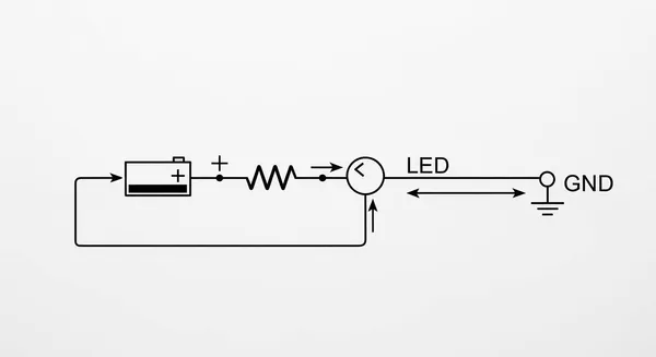
The Current Return Path
Electricity flows in a loop. For a circuit to work, current must have a complete path from the power source, through the components, and back to the source. The gnd provides the main return path for current. Think of it like a plumbing system: water flows from the pump, through the pipes, and must have a return pipe leading back to the pump.
The process of completing the current path works like this:
- Electrons leave the negative terminal of the power source (like a battery).
- They travel through the circuit, powering components like LEDs and microchips.
- After passing through the components, they flow to the gnd line.
- The gnd line acts as a wide, clear highway, guiding the current back to the power source's positive terminal.
This continuous loop is the essence of a functioning circuit. The ground offers a low-resistance return path, ensuring current flows smoothly and efficiently. Without this return path for current, the circuit is open, and no current will flow at all.
The Importance of a Ground Wire for Safety
Beyond circuit function, the ground wire is a critical safety feature, especially in devices powered by wall outlets. The purpose of a ground wire is to protect users from electric shock in case of a fault. This is why many plugs have a third prong—the ground pin.
So, how does a ground wire work? Inside an appliance with a metal case, the ground wire connects the case directly to the earth ground.
Safety Note: A fault condition occurs when a "hot" wire accidentally touches the metal casing of a device due to damaged insulation.
Without a ground connection, the metal case would become energized at a dangerous voltage. Anyone touching it would create a return path for the current through their body, resulting in a severe electric shock. The ground wire provides a much easier and low-resistance return path. This causes a massive surge of current to flow to ground, which instantly trips the circuit breaker or blows a fuse, cutting off power. The importance of a ground wire cannot be overstated for user safety.
International standards exist to enforce this level of safety. These codes ensure that grounding systems are designed and installed correctly. Key standards include:
- IEC 60364: An international standard for low-voltage electrical installations, with Section 54 specifically detailing earthing arrangements.
- NEC 250: Part of the National Electrical Code used widely in the US, dedicated entirely to grounding and bonding.
- IEEE 80: A guide for safety in AC substation grounding.
These regulations define the purpose of a ground wire and mandate its correct implementation, making electronics safer for everyone.
Understanding Different Types of Ground

The term "ground" can mean different things in different contexts. While all grounds act as a reference, their specific jobs can vary. Understanding the different types of grounds is key to designing and troubleshooting electronics. We can compare these grounds to building a house. The Earth ground is the solid foundation, the chassis ground is the metal frame of the house, and a signal ground is the floor of a specific room. Let's explore the main types of grounds.
Earth Ground
Earth ground is the most literal type of ground. It is a physical connection to the Earth itself. This connection uses a long metal rod driven deep into the soil. The Earth acts as a massive electrical conductor, able to absorb huge amounts of electrical charge without its potential changing. Its primary purpose is safety. The ground wire in a three-prong plug connects an appliance's metal case directly to this Earth ground.
This connection protects users from electric shock. It also provides a safe path for electrostatic discharge (ESD). Static charges can build up on surfaces and damage sensitive electronics. A proper Earth ground connection gives these charges a low-resistance path to dissipate safely into the Earth, protecting components.
For a safe and effective Earth ground, technicians must follow strict technical standards. The National Electrical Code (NEC) Article 250 provides detailed rules for grounding.
Key requirements for a proper Earth ground include:
- The path to ground must be permanent and continuous.
- The grounding electrode (the metal rod) must be installed correctly, often at least 1.5 meters from the building.
- The ground wire and electrode should be made of the same material to prevent corrosion.
- The total resistance of the ground connection should be very low, ideally less than 1.0 ohm, to ensure it can handle fault currents.
All ESD protective equipment at a workstation, like wrist straps and mats, should connect to a common point. This point then connects to the equipment ground, ensuring everything is at the same electrical potential.
Chassis Ground
Chassis ground is the connection to the metal frame or enclosure of an electronic device. This frame acts as a local gnd reference point for the circuits inside. In many devices, like computers or amplifiers, the chassis ground connects directly to the Earth ground through the ground wire in the power cord. This provides an extra layer of safety. If a hot wire touches the metal case, the current flows safely to Earth ground and trips the circuit breaker.
The chassis ground also serves another important function: shielding.
- The metal enclosure forms a protective barrier known as a Faraday cage.
- This cage shields the internal components from external electromagnetic interference (EMI).
- It also prevents the device from emitting its own EMI, which could interfere with other nearby electronics.
By connecting the shield to the system gnd, the chassis ground protects the delicate circuits inside from outside electrical noise.
Analog Ground (AGND)
In mixed-signal circuits that handle both analog and digital signals, keeping grounds separate is crucial. An analog ground (AGND) is the dedicated gnd return path for sensitive analog components. This type of signal ground ensures that clean, stable voltage references are available for analog parts.
Many components require a dedicated analog ground to function correctly:
- Analog-to-Digital Converters (ADCs) and Digital-to-Analog Converters (DACs) need a clean gnd reference for accurate measurements.
- Amplifiers and voltage references depend on a stable analog ground to avoid amplifying unwanted noise.
- Clock generators should be treated as analog components and connected to the analog ground to prevent clock jitter, which degrades system performance.
Noise on the analog ground plane can seriously impact an ADC's performance. Any voltage difference between the analog ground and digital ground can introduce jitter into the sampling clock. This jitter reduces the Signal-to-Noise Ratio (SNR), harming the precision of the conversion. Therefore, a clean analog ground is essential for high-fidelity signal processing. This signal ground provides a quiet reference for sensitive circuits.
Digital Ground (DGND)
A digital ground (DGND) is the current return path for digital components like microcontrollers, logic gates, and memory chips. This signal ground is often noisy compared to an analog ground. Digital circuits switch between high and low states very quickly. These rapid changes create sudden spikes of current.
This process generates noise, often called "ground bounce":
- Fast-switching digital logic gates have a small amount of inductance in their physical leads.
- When the gate switches, a rapid change in current flows through this inductance.
- This creates a small, temporary voltage spike on the gnd line (
V = L * di/dt). - This spike causes the gnd potential inside the chip to "bounce" relative to the external gnd.
This digital noise can interfere with other parts of the circuit. If this noisy digital ground mixes with the analog ground, it can corrupt sensitive analog signals. For this reason, designers often use separate ground planes for AGND and DGND, connecting them at only a single point. This technique isolates the noisy digital gnd from the quiet analog gnd, preserving signal integrity across the entire system. Understanding these different types of grounds is a major step toward building reliable electronics.
Proper Circuit Grounding Techniques

Proper circuit grounding is the foundation of a stable and reliable electronic device. A well-designed ground system minimizes noise, prevents interference, and is essential for maintaining signal integrity. Without careful planning, even the best components can fail to perform as expected. Mastering circuit grounding techniques is a critical skill for any electronics designer working on a modern PCB.
What is Ground Noise?
Ground noise refers to unwanted voltage fluctuations on a gnd line that should ideally be at a stable 0V. This noise can corrupt signals and cause a circuit to malfunction. The ground potential is no longer a stable reference. The primary sources of this noise on a PCB include:
- Switching Noise: Fast-switching digital components create sudden current spikes. This causes the gnd voltage to "bounce," generating high-frequency noise and EMI.
- Ground Loops: When a circuit has multiple paths to ground, small differences in ground impedance can create loops where unwanted current flows, introducing noise.
- Crosstalk: Signals from adjacent traces on a PCB can electromagnetically couple, creating interference that degrades signal integrity.
Engineers use tools like oscilloscopes and spectrum analyzers to measure this noise and ensure the gnd is clean.
Why Separate AGND and DGND?
A common technique to manage noise is to separate the analog ground (AGND) from the digital ground (DGND). The goal is to isolate sensitive analog components from the noisy gnd of the digital circuit. When grounds are separated, they are often connected at a single point in a "star ground" configuration. This method connects all ground segments to one central gnd point, preventing low-frequency loops.
However, for most modern PCB layout designs, experts now recommend a unified, solid ground plane. A large, unbroken ground plane offers a much lower ground impedance path for return currents. This approach is often more effective at minimizing EMI and preserving signal integrity than splitting the ground. The key is a smart component layout to keep noisy digital return paths away from sensitive analog circuits on the shared gnd plane.
Ensuring Signal Integrity
Excellent signal integrity depends on a low-impedance return path, which a solid gnd plane provides. On a high-speed PCB, the return current wants to flow directly underneath the signal trace. A continuous ground plane allows this, minimizing the loop area, which in turn reduces EMI and preserves signal integrity. Any break or split in the ground plane can force the return current to take a longer path, increasing ground impedance and creating significant noise issues that harm signal integrity.
Expertise in these considerations for handling ground in pcb design is why companies like Nova Technology Company (HK) Limited, a HiSilicon-designated solutions partner, can create reliable, high-performance electronic solutions. Their work shows how a proper ground connection is fundamental to a successful product. A thoughtful PCB layout that prioritizes a clean gnd path is crucial for managing EMI and achieving optimal circuit performance and signal integrity.
In electronics, gnd is far more than just a wire; it is the fundamental reference that gives every voltage in a circuit its meaning. A stable gnd ensures the entire electronics system operates predictably. Understanding its three primary roles is key to building a successful circuit.
Key Takeaways 💡
- 0V Reference: The gnd provides a stable baseline for all measurements.
- Current Return Path: It completes the circuit, allowing electricity to flow.
- Safety: A proper ground connection protects users from electric shock.
Mastering the principles of ground is a major step toward creating reliable and safe electronics. A well-planned gnd prevents noise, ensures signal integrity, and makes every circuit perform as intended.
FAQ
What is a virtual ground?
A virtual ground is a circuit node held at a stable reference potential. It is not directly connected to the main circuit gnd. Operational amplifiers often create a virtual ground. This virtual ground behaves like the real ground for signal purposes, providing a stable 0V point.
Why is a ground wire important on a PCB?
A ground wire on a printed circuit board (PCB) is essential. The ground wire provides a return path for current and helps manage electromagnetic interference (EMI). A good ground wire on a PCB ensures signal integrity. A poor ground wire on a PCB can cause many problems.
| Function of a Ground Wire on a PCB | Benefit |
|---|---|
| Provides a return path | Completes the circuit for proper function. |
| Manages EMI | Reduces unwanted noise. |
| Stabilizes gnd reference | Ensures reliable component performance. |
Can a bad ground wire cause EMI?
Yes, a bad ground wire is a common source of EMI. A poorly designed ground wire on a PCB can act like an antenna. It radiates noise generated by the circuit, creating EMI. This EMI can interfere with other electronics. Proper ground wire design on a PCB is critical to minimize EMI.
Is gnd always 0V?
The gnd is the reference point, which designers define as 0V. All other voltages are measured relative to this gnd. A concept like a virtual ground also creates a 0V reference point without a physical connection to the main ground. The gnd itself provides the baseline for the entire system.


