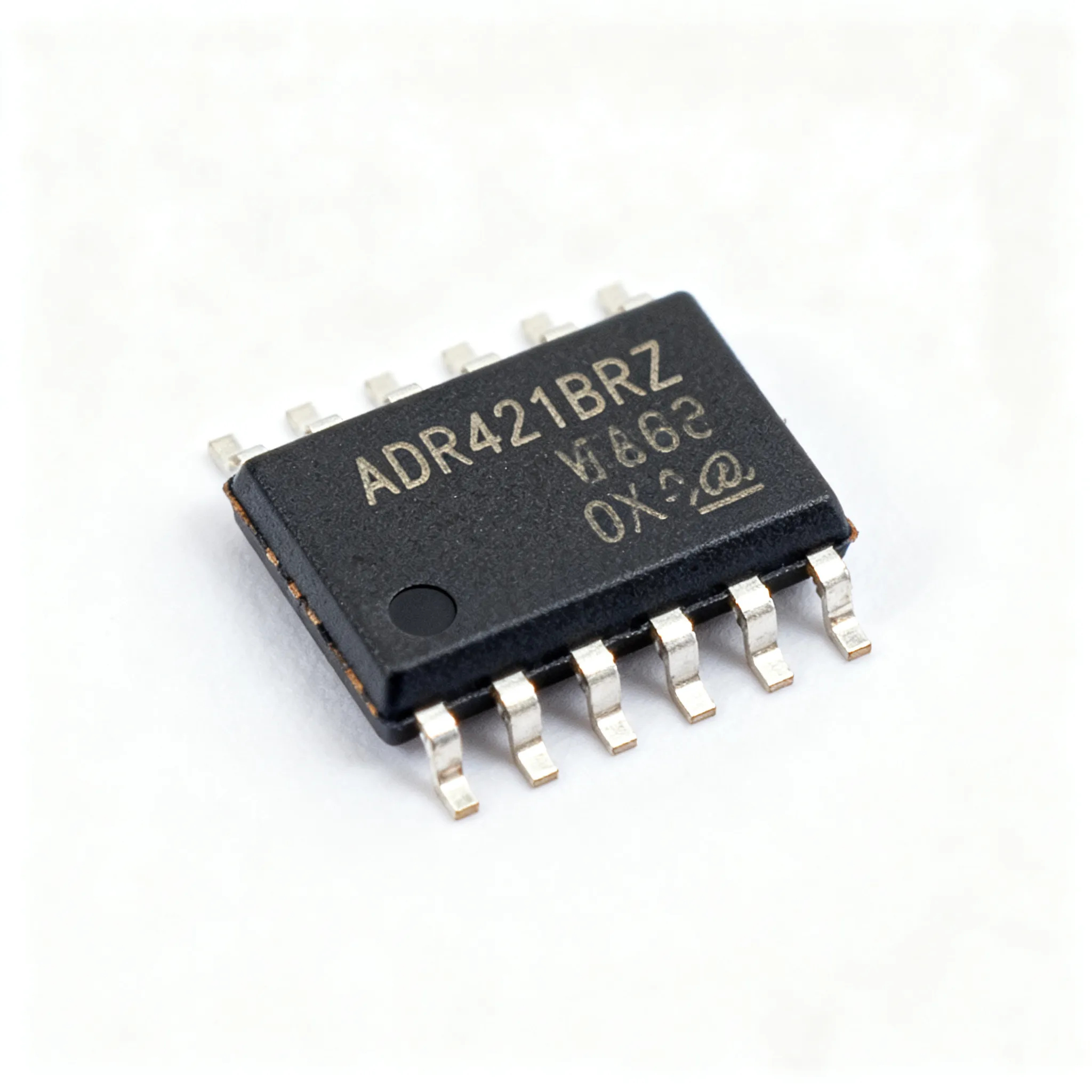
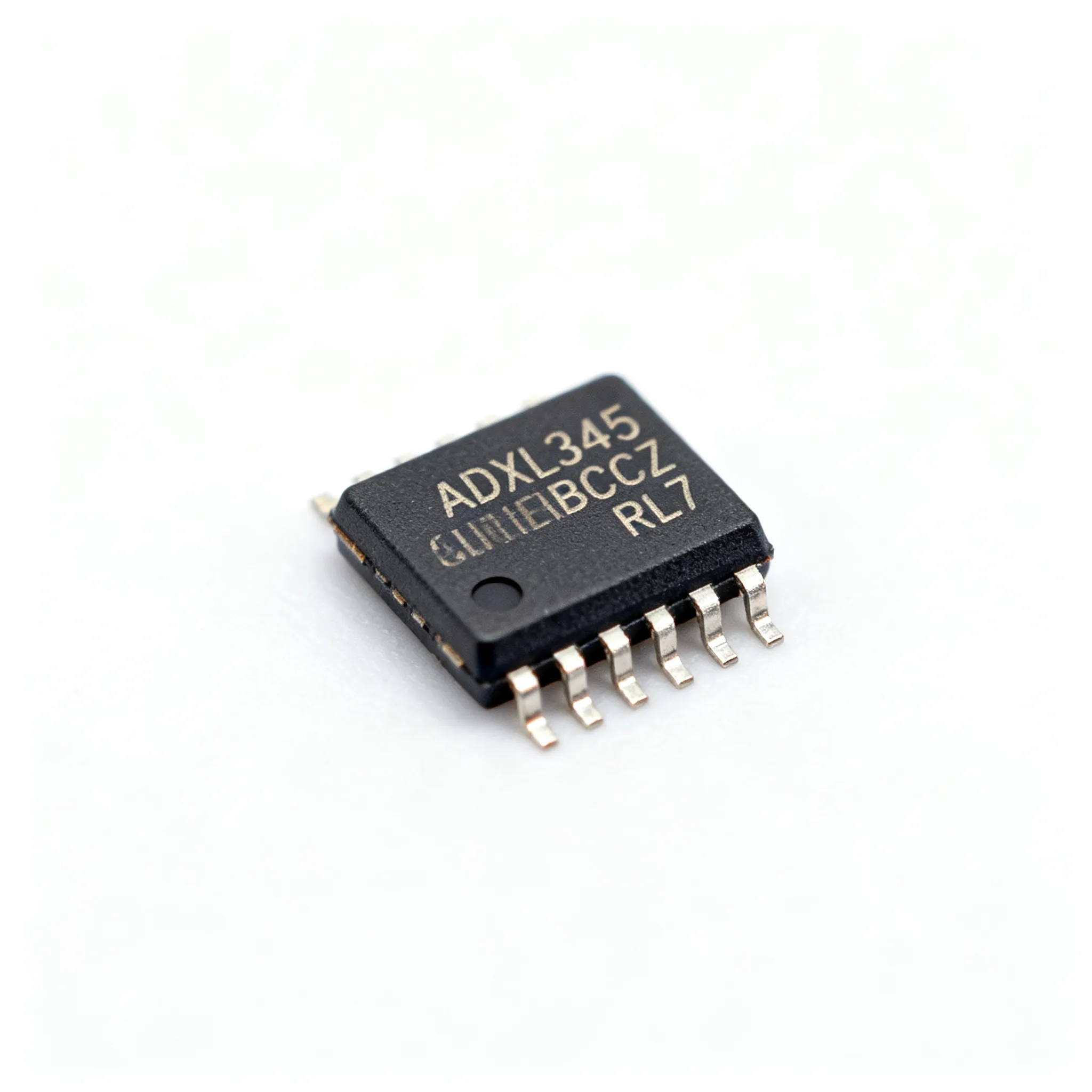
ADXL345BCCZ-RL7 Datasheet and Pinout: Specs for Design and Sourcing
ADXL345BCCZ-RL7 datasheet essentials, pinout overview, key specs, and design/sourcing checks for engineers and buyers. Request a quote on IC-Online.
Why the ADXL345 Keeps Showing Up on BOMs — and Why the -RL7 Suffix Matters
The ADXL345BCCZ-RL7 continues to appear on bills of material across industrial condition monitoring, medical instrumentation and consumer wearables because it packs a full 3-axis digital accelerometer into a tiny 3×5×1 mm LGA package with a mature, well-understood register set. Design teams reach for the ADXL345 when they need four selectable measurement ranges (±2/4/8/16 g), an onboard 32-level FIFO and a proven SPI/I²C interface that multiple firmware libraries already support. The part is not marked “not recommended for new designs” by Analog Devices, and its longevity has made it a low-risk choice for products with multi-year lifecycles.
What trips up many first-time buyers is the suffix. The base die in ADXL345BCCZ-RL7 is identical to the tray or cut-tape ADXL345BCCZ, but the “‑RL7” tells procurement exactly how the parts arrive: a 13‑inch reel holding 2,500 units, ready for high-speed pick‑and‑place. Ordering the wrong reel code can stall a production line when the line is set up for full reels and you receive cut tape or a JEDEC tray instead. For volume pricing context, PCBSync notes that ADI’s 1k list price starts at $3.40 while the RL7 reel code has been listed around $1.19 in volume at LCSC, reflecting the pricing advantage of bulk reel purchasing. Confirming the exact suffix on your BOM before you release a purchase order is one of the simplest ways to avoid a costly line‑down situation.
Pin-by-Pin Breakdown and Key Electrical Parameters You Should Verify Before Prototyping
The ADXL345BCCZ-RL7 14‑pin LGA package is compact, and every pin serves a specific role in power sequencing, communication and interrupt handling. A quick walk‑through of the pin functions helps avoid the most common prototype bring‑up problems. The datasheet, available via AiPCBA and LCSC, provides full timing diagrams, but the following pin‑by‑pin summary gives you the essentials.
- VDD (pin 14): Core supply; connect to 2.0–3.6 V. The internal LDO regulates the MEMS sensor and analog front‑end.
- VDDIO (pin 1): Interface voltage for the logic pins. Set between 1.7 V and VDD to match your host microcontroller I/O level without external level shifters.
- GND (pins 11, 12): Both ground pads must be connected to a low‑impedance plane to meet noise performance.
- CS (pin 7): Chip select for SPI mode. Tie high (to VDDIO) for I²C mode. In SPI, drive low to enable communication.
- SDA/SDI/SDIO (pin 13) and SCL/SCLK (pin 6): I²C data/clock or SPI serial data lines. The ALT ADDRESS pin (pin 5) selects the I²C slave address when held high or low.
- INT1 (pin 8) and INT2 (pin 9): Configurable interrupts for data ready, activity/inactivity detection, free‑fall, or watermark events. Route these to MCU GPIOs with a pull‑up.
- Reserved (pins 2, 3, 4, 10): Leave these unconnected or tie as recommended in the datasheet.
Tip: Always power VDDIO before or simultaneously with VDD to prevent current injection into the I/O cells. A sequencing delay between VDD and VDDIO outside the datasheet limits can cause a latch‑up condition that requires a power cycle to clear.
Below is a condensed parameter table taken directly from the datasheet’s key electrical specifications. Use it as a design‑in sanity check before you spin a board.
| Parameter | Value / Range | Unit & Conditions |
|---|---|---|
| Measurement ranges | ±2, ±4, ±8, ±16 | g, software selectable |
| Typical sensitivity | 256 (2g) to 32 (16g) | LSB/g at 10‑bit fixed mode |
| Output resolution | 10‑bit fixed / 13‑bit high‑resolution | bits, via internal oversampling |
| Output data rate (ODR) | 0.1 to 3200 Hz | Hz, programmable |
| Noise density (X,Y axes) | 275 | µg/√Hz typical @ 2g, full bandwidth |
| Noise density (Z axis) | 350 | µg/√Hz typical |
| Supply voltage (VDD) | 2.0 to 3.6 | V |
| Interface voltage (VDDIO) | 1.7 to VDD | V |
| Current in measurement mode | 35–140 | µA, depending on ODR and mode |
| Standby current | 0.1 | µA typical |
| Operating temperature | –40 to +85 | °C |
| Acceleration shock survival | 10,000 | g (unpowered) |
The wide ODR range lets you trade off data throughput and power. For a tilt‑sensing thermostat you might run at 12.5 Hz and draw roughly 35 µA, while a vibration logger may push 800 Hz and the full 140 µA. The separate VDDIO pin is the key to mixing a 1.8 V MCU with a 2.5 V analog core—no external translator chip required.
When the ADXL345BCCZ-RL7 Isn't the Only Answer: Realistic Alternative Accelerometers
While the ADXL345BCCZ-RL7 covers a wide performance envelope, three alternative MEMS accelerometers—LIS3DH, MMA8451Q and the newer ADXL346—can resolve a specific design constraint better. The choice often hinges on package height, FIFO depth, power consumption at a given ODR, or interface voltage flexibility. A side‑by‑side comparison using parametric data aggregated on Octopart and updated on Datasheets.com helps you evaluate if a swap is worth the firmware retest.
| Comparison Metric | ADXL345BCCZ-RL7 | LIS3DH (STMicro) | MMA8451Q (NXP) | Selection Note |
|---|---|---|---|---|
| G‑range | ±2/4/8/16 g | ±2/4/8/16 g | ±2/4/8 g | MMA8451Q limited to ±8 g; for 16‑g impact sensing, avoid. |
| FIFO depth | 32 samples | 32 levels (10‑bit) | 32 samples | All three similar, though FIFO modes differ slightly. |
| Typical current @ 100 Hz ODR | ~40 µA (2.5 V VDD) | ~11 µA (low‑power mode) | ~6 µA (low‑power) | LIS3DH and MMA8451Q significantly lower power for battery applications. |
| Package (mm) | 3×5×1 LGA-14 | 3×3×1 LGA-16 | 3×3×1 QFN-16 | ADXL345’s 3×5 mm footprint may require more board space. |
| Interface & I/O voltage | SPI/I²C, VDDIO 1.7–VDD | SPI/I²C, 1.71–3.6 V logic | I²C only, 1.95–3.6 V | MMA8451Q lacks SPI; verify MCU peripherals. |
| Tap/Double‑Tap | Yes | Yes | Yes | All three support basic gesture interrupts. |
Key takeaway: If your product runs on a coin cell and needs sub‑10 µA motion wake‑up, the LIS3DH or MMA8451Q will likely give you longer battery life. If you need 16‑g ranges and SPI communication, the ADXL345 still fits perfectly. The ADXL346 adds a 13‑bit high‑resolution mode and deeper FIFO but shares the same footprint and pinout as the ADXL345; it can be evaluated as a performance upgrade with the same PCB, but always verify register compatibility and power‑on timing. No alternative is a “guaranteed drop‑in” without your own firmware validation.
Design-in and Sourcing Traps That Trip Up Engineers Ordering the RL7 Reel
The ADXL345BCCZ-RL7 datasheet revision history includes a note that Rev. G publishes no moisture sensitivity level (MSL) class, only a J‑STD‑020D.1 soldering profile with a 260 °C Pb‑free peak. In practice, many assembly houses treat the LGA‑14 package as MSL‑3, requiring a bake before reflow if the factory floor‑life limit has been exceeded. Failing to specify the MSL condition on your incoming‑inspection checklist has caused latent popcorning failures that only surface in thermal cycling.
Equally important is the land pattern. The 14‑pin LGA has 0.25 mm pads on a 0.5 mm pitch, which demands tight solder mask registration and a stencil aperture optimized for the small pad geometry. Many engineers grab a generic LGA‑14 footprint from a library, but the ADXL345 expects a central cavity (the sensor element must not be covered by soldermask). Verified ECAD models that respect the datasheet‑recommended solder mask opening and stencil can be downloaded from SnapMagic Search, with exports for Altium, Cadence Allegro, KiCad and others. Using a verified footprint eliminates guesswork on the paste‑aperture ratio for the tiny perimeter pads.
The table below captures the most common hardware checks that differentiate a smooth first‑spin from a board‑revision delay.
| Checkpoint | What the Datasheet Says | Common Pitfall |
|---|---|---|
| Solder reflow peak | 260 °C max (Pb‑free), J‑STD‑020D.1 | Using a lead‑free profile calibrated for larger QFNs can overheat the LGA. |
| Moisture sensitivity | No explicit MSL; treat as MSL‑3 | Assuming MSL‑1 and skipping bake after extended floor exposure. |
| Pad 0.25 mm × 0.65 mm | 0.5 mm pitch, NSMD recommended | Using a standard 0.3‑mm pad; may cause shorts or insufficient standoff. |
| Stencil aperture | 1:1 area ratio to pad, 100 µm foil | Applying a general 80 % area reduction starves the LGA of solder volume. |
| Central cavity | No copper or soldermask under sensor | Filling the cavity center with a ground pour raises the sensor and stresses the accelerometer die. |
On the procurement side, the RL7 reel code eliminates a whole class of headaches if the buyer confirms three items before cutting a PO:
- Reel quantity: Ask the distributor to confirm the reel contains exactly 2,500 pieces, not any residual quantity from a partial reel.
- Reel size and carrier tape: Most pick‑and‑place feeders for 13‑inch reels are standard, but verify the tape‑and‑reel orientation matches your feeder bank.
- Date codes and shelf life: Request a maximum date code age (e.g., ≤2 years from manufacturing) and a solderability test report if the parts have been stored for more than 12 months.
- Allocation‑backed lead time: Do not rely on a verbal promise. Require a written lead‑time confirmation from the authorized distributor. If the ADXL345 is sole‑sourced on your BOM, consider a non‑cancellable, non‑returnable (NCNR) buffer order with an agreed shipment schedule.
Finally, verify lifecycle status directly with ADI or your franchised distributor. While the ADXL345 is currently active, long‑lived product programs benefit from a twice‑yearly PCN (product change notification) review to catch any impending package or test‑site migration.
Questions Designers and Buyers Ask About the ADXL345BCCZ-RL7 Before Placing an Order
Senior engineers and procurement leads tend to ask the same practical questions. The answers below draw from the datasheet, field experience and supplier‑engagement best practices.
Q: What’s the difference between the ADXL345BCCZ and the ADXL345BCCZ-RL7 suffix?
A: The base die is identical. The ‑RL7 designates a 13‑inch reel with 2,500 units for automated placement, as opposed to tray or smaller‑quantity packaging. Always verify the reel code on your BOM to avoid receiving cut‑tape or tray when your line expects full reels. Even if the part number otherwise matches, the wrong package suffix can mean a line stoppage.
Q: How do I interface the ADXL345 with a 1.8 V microcontroller given its separate VDD and VDDIO supplies?
A: VDDIO powers the I²C/SPI logic pins; set it to 1.8 V while VDD remains at 2.0–2.75 V (or 2.0–3.6 V for the full range). This decoupling lets you run the accelerometer core at a lower noise voltage without level shifters. Check the VDDIO power‑up sequence in the datasheet—VDDIO must rise before or simultaneously with VDD. A delay in VDDIO can forward‑bias ESD diodes and cause latch‑up, requiring a full power cycle to restore normal operation.
Q: Is the ADXL345 still recommended for new designs, or should I move to ADXL346 or ADXL343?
A: The ADXL345 is not NRND by ADI and remains widely available. If your design needs a wide ±16 g range or internal FIFO, the ADXL345 still fits. For lower power or a smaller 2×2 mm footprint, evaluate the ADXL346 or ADXL343, but verify register‑level compatibility. Review the parametric table on Datasheets.com to compare key specs side by side before committing to an alternative.
Q: How do I choose between 10‑bit fixed mode and 13‑bit high‑resolution mode, given the noise specification?
A: The difference comes from internal oversampling. In 13‑bit mode, the sensor runs at 800 Hz output data rate but provides lower noise (typically less than 1 LSB rms). 10‑bit mode lowers current but adds quantization noise. Match the mode to your motion bandwidth: for tilt or slow human‑motion detection, 13‑bit at 100 Hz ODR gives cleaner data; for high‑speed vibration trending, 10‑bit at 800 Hz may suffice. Remember that the noise density floor of 275 µg/√Hz is always active regardless of resolution mode, so trading bits for power can make sense in high‑vibration environments where mechanical noise dominates.
Q: What is the typical lead time and reel size for ‑RL7 parts, and are there any known allocation risks?
A: The ‑RL7 suffix denotes 2,500 pieces on a 13‑inch reel. Lead time is allocation‑sensitive; always confirm availability and a binding lead time via RFQ. For reference, broad MEMS accelerometer classes have historically seen standard lead times in the 8–12 week range during stable cycles, but you should not plan your MRP around that figure. No published allocation has been active for the ADXL345 as of early 2025, but buyers should monitor distributor stock on Octopart and, if the part is sole‑sourced, consider a buffer stock arrangement with scheduled call‑offs.
Q: Which PCB land pattern and CAD model should I use for the 14‑pin LGA package?
A: Follow the land pattern from the ADXL345 datasheet Rev. G, noting the 0.25 mm pad size and 0.5 mm pitch. Verified ECAD models with correct solder mask opening and stencil can be downloaded from SnapMagic Search, supporting Allegro, Altium, KiCad and others. Using an unverified community footprint risks mask slivers and insufficient solder volume, which often manifest as intermittent interconnects that pass in‑circuit test but fail under vibration.
Whether you are validating a new sensor on a prototype or locking in a long‑term procurement strategy, the ADXL345BCCZ-RL7 provides a stable, well‑documented baseline. Getting the reel suffix, assembly rules and lead‑time terms right early saves weeks of rework later. For up‑to‑date pricing, availability and reel‑conformance details, request a quote or upload your full BOM via IC-Online and a specialist will provide allocation‑backed options with flexible MOQs.
References & Further Reading
- ADXL345BCCZ: Specs, Pinout, Alternatives & Sourcing – PCBSync
- ADXL345BCCZ-RL7 Distributors, Price Comparison & Datasheets – Octopart
- ADXL345BCCZ-RL7 Datasheet PDF & Tech Specs – Datasheets.com
- ADXL345BCCZ-RL7 Symbol, Footprint & 3D Model – SnapMagic Search
- ADXL345BCCZ-RL7 Datasheet PDF – AiPCBA
- ADXL345BCCZ-RL7 Datasheet – LCSC Electronics
- IC-Online – Electronic Component Sourcing & RFQ Platform