ASTMLPA-18-100.000MHZ-LJ-E-T 100 MHz MEMS Oscillator: Key Specs and Selection Criteria
Expert guide on ASTMLPA-18-100.000MHZ-LJ-E-T 100 MHz MEMS Oscillator: Key Specs and Selection Criteria. Technical specs, applications, sourcing tips for engineers and buyers.
ASTMLPA-18-100.000MHZ-LJ-E-T 100 MHz MEMS Oscillator: Key Specs, Variants, and Selection Guide
Why This 100 MHz MEMS Oscillator Is Showing Up on More BOMs
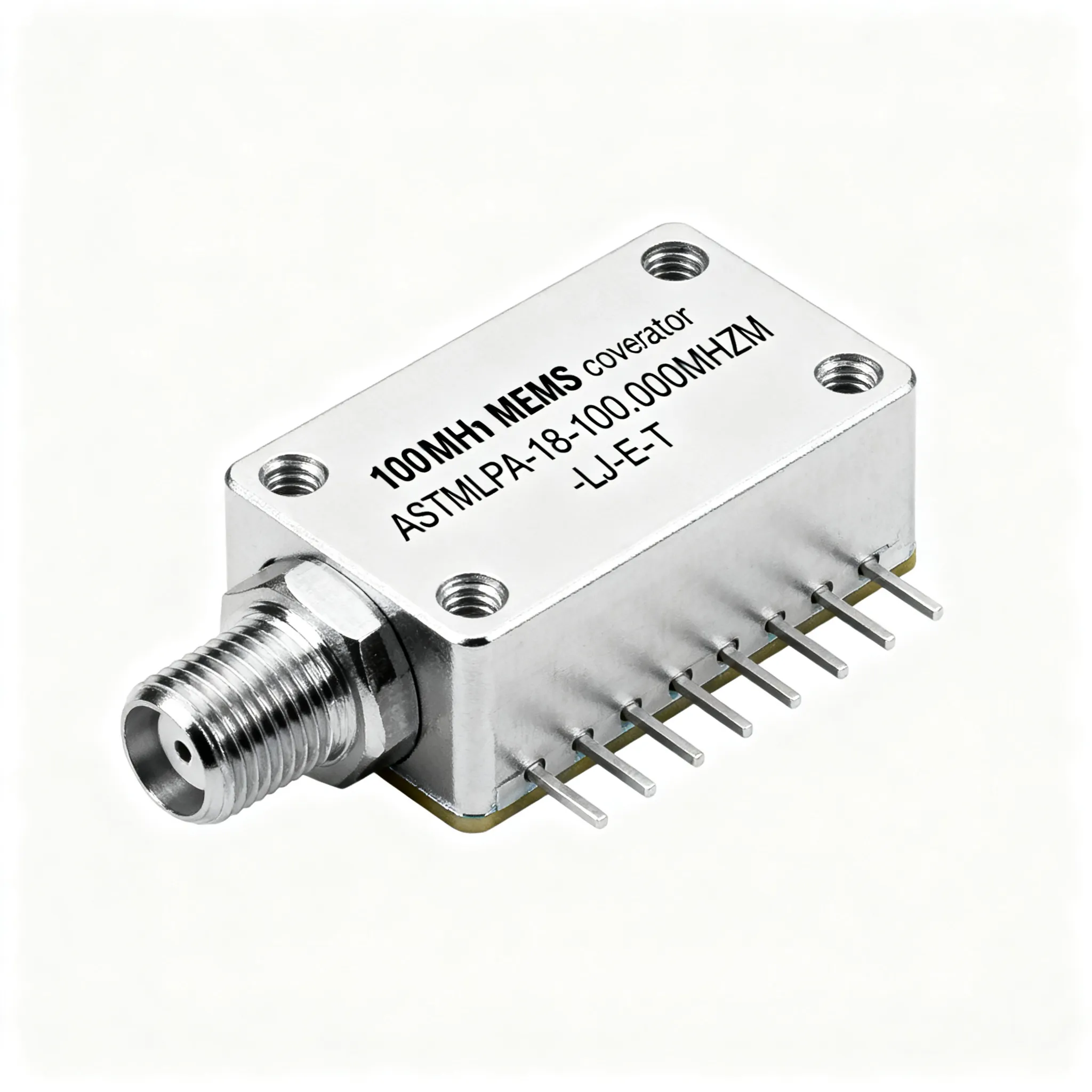
Designers of IoT edge nodes, portable medical instruments, and compact industrial sensors are moving away from legacy quartz oscillators. They need a 100 MHz clock source that combines low power, small footprint, and reliable startup over temperature extremes—without the mechanical fragility of a quartz crystal. The ASTMLPA-18-100.000MHZ-LJ-E-T from Abracon’s ASTMLP family addresses exactly that pressure point. Based on a programmable MEMS resonator and PLL architecture, this oscillator delivers stable 100 MHz LVCMOS output from a 1.8 V supply while drawing just 3.5 mA typical. It fits in a 2.0 × 1.6 mm SMD package, leaving more board space for the actual sensor or radio.
The part is in stock at major distributors such as Avnet and Digi-Key, which is critical when procurement teams are trying to avoid the 16‑week lead times that plagued quartz-based oscillators last year. The datasheet available through this TI-hosted PDF confirms the flexibility of the platform: the same MEMS core can be factory‑programmed for frequencies from 1 MHz to 150 MHz, but the 100 MHz variant we’re focusing on is a common sweet spot for high‑speed serial interfaces and microcontroller clocking.
The “LJ” suffix in ASTMLPA-18-100.000MHZ-LJ-E-T is the key to harsh environment designs. It guarantees operation over the full industrial temperature range of -40°C to +85°C, while the “EJ” counterpart stays within -20°C to +70°C. If your device is heading into a factory floor, an outdoor enclosure, or an unventilated cabinet, that extra 45°C margin can be the difference between a system that boots every time and one that fails intermittently when the mercury drops. In the following sections, we’ll dissect the electrical performance, contrast the available temperature grades, compare the part with SiTime MEMS alternatives, and walk through the design‑in and sourcing details that engineers and buyers need to sign off without surprises.
ASTMLPA-18-100.000MHZ-LJ-E-T Under the Hood: Key Specs and MEMS Architecture
At its core, the ASTMLPA-18-100.000MHZ-LJ-E-T uses a silicon MEMS resonator as the frequency reference, followed by a low‑noise PLL and a LVCMOS output driver. Unlike a quartz crystal, the MEMS element is vacuum‑sealed at the wafer level and is immune to shock and vibration, which contributes to the consistent startup behavior and low jitter. The datasheet (TI PDF) and distributor descriptions on Octopart for the 25 MHz variant confirm that the ASTMLP family shares a common architecture, so the 100 MHz version benefits from the same proven silicon design.
Tip: When you specify a MEMS oscillator for a 100 MHz clock, pay attention to the rise/fall time and duty cycle limits. With a nominal 2.5 ns rise/fall time and a 55% typical duty cycle, this oscillator can comfortably drive most LVCMOS inputs without excessive slew‑rate distortion—provided your receiver’s minimum pulse width specification is respected.
Below is a summary of the key electrical and environmental parameters, compiled from the manufacturer’s datasheet and distributor listings.
| Parameter | Value/Range | Unit/Notes |
|---|---|---|
| Frequency | 100.000 | MHz |
| Frequency Stability (all conditions) | ±20 | ppm, inclusive of initial tolerance, temperature, load, voltage, aging (1st year) |
| Supply Voltage (VDD) | 1.8 ±5% | V |
| Output Type | LVCMOS | Single-ended |
| Load Capacitance | 15 | pF (max) |
| Duty Cycle | 55 ±5 | % (at 50% VDD) |
| Rise/Fall Time | 2.5 (max) | ns (20%–80% VDD, 15 pF load) |
| Supply Current (no load) | 3.5 (typ), 4.9 (max) | mA |
| RMS Period Jitter | 2 (typ) | ps (12 kHz to 20 MHz integration bandwidth) |
| Startup Time | 5 (max) | ms |
| Standby Current (disable) | 10 | µA (max) |
| Operating Temperature | -40 to +85 | °C (LJ suffix) |
| Package / Footprint | 2.0 × 1.6 × 0.75 | mm, 4‑pad SMD |
The MEMS‑based PLL architecture is what keeps the jitter low (2 ps RMS typical) and the startup time predictable. While a quartz oscillator can require a carefully tuned gain‑margin to reliably start over temperature, the MEMS resonator’s high Q and the integrated PLL lock the output frequency within 5 ms of applying power. The standby current of less than 10 µA when the enable pin is pulled low is a boon for battery‑powered systems that need to conserve every microamp during sleep cycles. In the next section, we’ll see how the industrial temperature version stacks up against the commercial sibling and a leading SiTime alternative.
Picking the Right Temperature Grade: ASTMLPA-18-100.000MHZ-LJ-E-T vs. EJ-E-T and SiTime MEMS Oscillators
All ASTMLPA-18‑100.000MHZ variants share the same silicon, but the suffix letter determines the operating temperature range. The “LJ” suffix in ASTMLPA-18-100.000MHZ-LJ-E-T denotes industrial grade (-40°C to +85°C), while the “EJ‑E‑T” variant (available at Digi-Key) covers the commercial range of -20°C to +70°C. Electrical specifications—frequency, stability, jitter, supply voltage, drive strength—are identical between the two. The only difference is the guaranteed performance boundaries. If you’re designing a consumer gadget that will never see freezing temperatures, the EJ part is a cost‑effective choice. But for outdoor wireless infrastructure, industrial motor drives, or automotive‑adjacent ECU applications, the LJ grade is the safer bet.
No BOM choice is complete without a cross‑check against a competitive alternative. The SiTime SiT8008 family is a widely used MEMS oscillator that also offers a 100 MHz, 1.8 V option. The SiT8008BI‑13‑18E‑100.000000, for example, delivers ±25 ppm stability, integrates an on‑chip LDO, and is available in a 2.5 × 2.0 mm package. The comparison table below highlights the key differences that can influence your final selection.
| Comparison Metric | ASTMLPA-18-100.000MHZ-LJ-E-T (Abracon) | ASTMLPA-18-100.000MHZ-EJ-E-T (Abracon) | SiT8008BI-13-18E-100.000000 (SiTime) | Selection Criteria & Failure Boundary |
|---|---|---|---|---|
| Temperature Range | -40°C to +85°C | -20°C to +70°C | -40°C to +85°C | Choose LJ or SiTime if the product must start at -40°C. EJ is inadequate for freezing environments. |
| Frequency Stability | ±20 ppm | ±20 ppm | ±25 ppm | ±20 ppm gives slightly more margin for timing budget vs. ±25 ppm, especially in PLL designs. |
| Supply Voltage | 1.8 V ±5% | 1.8 V ±5% | 1.8 V ±5% (with internal LDO) | Internal LDO in SiTime can improve PSRR but adds quiescent current; check your rail noise. |
| Package (mm) | 2.0 × 1.6 | 2.0 × 1.6 | 2.5 × 2.0 (or 2.0 × 1.6 on request) | 2.0 × 1.6 mm is the smallest standard; verify footprint compatibility if swapping. |
| Typical Supply Current | 3.5 mA | 3.5 mA | 3.8 mA (no load) | Marginal 0.3 mA difference; important for coin‑cell or energy‑harvesting designs. |
| RMS Period Jitter | 2 ps (12 kHz‑20 MHz) | 2 ps | 1.5 ps (12 kHz‑20 MHz) | SiTime claims slightly lower jitter; both are adequate for 100 MHz logic. |
| Typical Lead Time (2025) | In stock at Avnet/Digi‑Key | In stock at Digi‑Key | Varies; check SiTime distributors | Availability often trumps spec; confirm real‑time inventory before BOM lock. |
Notice that the Abracon parts maintain a ±20 ppm stability window, which can be critical if your clock tree already pushes the ±50 ppm tolerance of a downstream Ethernet PHY. The SiT8008’s integrated LDO can be a double‑edged sword: it simplifies power‑supply filtering but consumes a bit more current. On the footprint front, the 2.0 × 1.6 mm package of the ASTMLP series is the smallest standard outline, allowing you to place the oscillator closer to the MCU or FPGA and reduce PCB parasitics. If you are already using a 2.5 × 2.0 mm land pattern, the SiTime part may drop in without a layout change, but you’ll lose the 2.0 × 1.6 mm area advantage. In the next section, we’ll turn to the practical side: how to design in the ASTMLPA-18-100.000MHZ-LJ-E-T and source it with confidence.
How to Design In and Source the ASTMLPA-18-100.000MHZ-LJ-E-T Without the Gotchas
Integrating a 100 MHz MEMS oscillator into a high‑speed digital design is straightforward, but overlooking a few details can lead to field failures or procurement headaches. Here’s a checklist of the most common pitfalls and the steps to avoid them.
- Match the duty cycle to your receiver. The ASTMLPA-18-100.000MHZ-LJ-E-T outputs a nominal 55% duty cycle, with a ±5% window. Some DDR memory controllers or clock buffers require a 50% ±5% duty cycle; a 55%‑high clock may violate the minimum low‑time spec. Check your receiver’s datasheet and, if necessary, add a passive RC network or use a clock buffer with duty‑cycle correction.
- Place the decoupling capacitor correctly. A 0.1 µF ceramic capacitor should be placed within 2 mm of the VDD pin (pad 4) and connected to the ground plane with a short, low‑inductance via. The datasheet (TI PDF) shows the recommended pad layout; keep the trace from the output pin to the load as short as possible to minimize reflections.
- Use the enable/disable pin for power savings. Pin 1 is an active‑high enable input. Driving it low disables the output and puts the oscillator into standby, drawing less than 10 µA. The output enable time is 5 ms maximum, so plan your wake‑up sequencing accordingly. If you don’t need sleep functionality, tie pin 1 directly to VDD.
- Double‑check the ordering code. The suffix “LJ” indicates industrial temperature, but a single‑letter mistake (e.g., ordering “EJ” for a freezer application) can cause a costly re‑spin. Always verify the full part number and the temperature range on the acknowledgment before releasing the PO.
- Source only from authorized distributors. Counterfeit oscillators are rare but not unheard of. Authorized channels like Avnet and Digi-Key guarantee traceability and factory‑fresh stock. If you need to buy from a broker, insist on a full test report and perform incoming inspection for frequency accuracy and jitter.
- Confirm PCB pad compatibility. The 2.0 × 1.6 mm package uses a 4‑pad land pattern with 0.7 mm pitch. The recommended pad dimensions are available in the datasheet. If you are replacing a 2.5 × 2.0 mm oscillator, you’ll need a layout change—don’t assume a drop‑in fit.
Tip: When you evaluate the first prototype, measure the output waveform with a 15 pF probe (or a low‑capacitance FET probe) to confirm that the 2.5 ns rise/fall time and 55% duty cycle are met at the load. Variations in board capacitance can slow edges, potentially causing timing violations in high‑speed receivers.
The table below summarizes the key design‑in parameters and their recommended limits, compiled from the datasheet and field experience with MEMS oscillators.
| Design Parameter | Recommended Value | Notes |
|---|---|---|
| VDD Bypass Capacitor | 0.1 µF X7R, 0402 or 0201 | Place ≤2 mm from pin 4; connect to ground plane with ≤1 via. |
| Output Load | ≤15 pF | Exceeds 15 pF may degrade rise/fall time and duty cycle. |
| Enable Pin (1) Logic High | ≥0.7×VDD | If unused, tie directly to VDD. |
| Output Enable Time | 5 ms (max) | Allow this delay before sampling the clock after wake‑up. |
| Trace Impedance | 50 Ω, single‑ended | Keep trace length < 25 mm to avoid reflections. |
| Storage Temperature | -55°C to +125°C | Do not exceed during reflow; peak reflow 260°C per JEDEC. |
Armed with these guidelines, you can confidently drop the ASTMLPA-18-100.000MHZ-LJ-E-T into your next design. The final section answers the questions that come up most often during the sign‑off meeting.
ASTMLPA-18-100.000MHZ-LJ-E-T: Questions Engineers Ask Before Signing Off
Here are the six most common questions we hear from engineers and buyers, with direct, actionable answers.
Q: What is the actual operating temperature range of the LJ suffix?
A: The LJ suffix guarantees operation from -40°C to +85°C. In contrast, the EJ suffix covers -20°C to +70°C. The part number letter “L” designates industrial temperature grade, as confirmed by the datasheet and distributor descriptions. If your product must boot at -40°C, you must order the LJ variant.
Q: Can I run this oscillator at 3.3 V?
A: No, the “-18” in the part number indicates a 1.8 V supply. The ASTMLP family offers 2.5 V and 3.3 V variants (e.g., ASTMLPA-33-…), but the ASTMLPA-18-100.000MHZ-LJ-E-T is fixed at 1.8 V ±5%. Applying 3.3 V will damage the device.
Q: What is the typical phase jitter of this 100 MHz MEMS oscillator?
A: The datasheet specifies 2 ps RMS period jitter, integrated over 12 kHz to 20 MHz. This low jitter is a result of the MEMS resonator and PLL architecture. For most digital applications, 2 ps jitter is more than adequate; if your design requires sub‑picosecond jitter, you may need to look at differential oscillators.
Q: How does the enable/disable pin work and what is the power‑down current?
A: Pin 1 is an enable/disable input. Driving it low disables the output (high impedance) and puts the oscillator into standby, drawing less than 10 µA. Output enable time is typically 5 ms, as detailed in the datasheet. If you don’t need the disable function, tie pin 1 to VDD.
Q: Is there a direct drop‑in replacement from SiTime?
A: The SiT8008BI‑13‑18E‑100.000000 is a 100 MHz, 1.8 V, ±25 ppm, 2.5 × 2.0 mm oscillator that can be considered. However, the ASTMLPA-18-100.000MHZ-LJ-E-T uses a 2.0 × 1.6 mm footprint and offers ±20 ppm stability. Always check mechanical compatibility and performance requirements before substituting. The SiT8008 can also be ordered in a 2.0 × 1.6 mm package, but the standard offering is 2.5 × 2.0 mm, so verify the exact part number.
Q: What is the typical lead time for the ASTMLPA-18-100.000MHZ-LJ-E-T from distribution?
A: As of the latest checks, both Avnet and Digi-Key show stock, with lead times as short as a few days. Always verify real‑time inventory at Avnet and Digi-Key. If the industrial‑grade part is out of stock, the commercial EJ variant may be available as a temporary substitute for prototype testing, but always return to the LJ version for production.
References & Further Reading
- ASTMLP Series Datasheet (TI E2E PDF)
- Avnet product page for ASTMLPA-18-100.000MHZ-LJ-E-T
- Digi-Key product page for ASTMLPA-18-100.000MHZ-EJ-E-T
- Octopart listing for ASTMLPA-18-25.000MHZ-LJ-E-T (family reference)
- SiTime MHz Oscillators product page
- Abracon ASTMLP Family Datasheet on Digi-Key
- IC-Online – mixed BOM procurement and flexible MOQ
Whether you’re sourcing a single reel for a pilot build or negotiating a long‑term contract for a high‑volume IoT device, the ASTMLPA-18-100.000MHZ-LJ-E-T gives you a proven, available, and well‑documented 100 MHz clock. By cross‑checking the temperature grade, confirming the layout rules, and locking in supply through authorized distributors, you can avoid the gotchas that often delay production. For more component insights and up‑to‑date inventory, visit IC-Online.