CMS32M5710L048 Datasheet and Pinout: Specs for Design and Sourcing
CMS32M5710L048 datasheet essentials, pinout overview, key specs, and design/sourcing checks for engineers and buyers. Request a quote on IC-Online.
Why the CMS32M5710L048 Matters in Today’s Supply Chain Maze
When a Volvo or Volkswagen production line halts because of component shortages, engineers on the shop floor hear the echo long after the news cycle moves on. The 2025 Nexperia export-control shock, documented by NextPCB’s shortage analysis, reminded everyone that single-source dependence on one geography or supplier can cascade into board spins and requalification nightmares. Against that backdrop, Chinese MCUs like the CMS32M5710L048 are moving from “interesting to have” to “must-evaluate” on many BOMs.
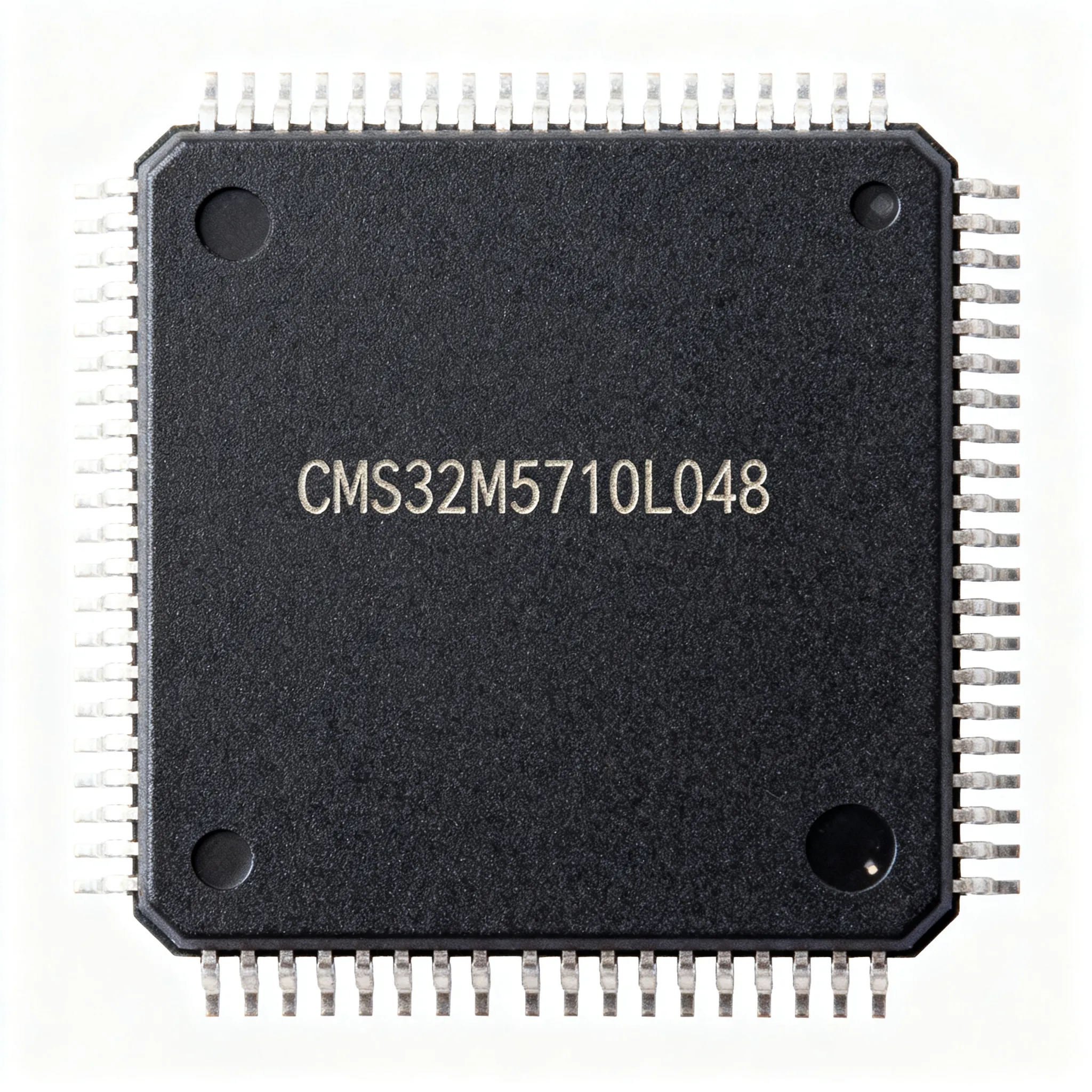
The CMS32M5710L048 is a Cortex‑M0 microcontroller from Cmsemicon that packs 64 KB Flash, an LQFP‑48 footprint, and a 64 MHz core into a part that you can drop into motor drives, digital power supplies, and sensor concentrators. The official datasheet is readily available through platforms such as pdf.elecfans.com, but the real work begins when you move from a PDF to a verified layout. Blindly assuming it’s a drop‑in for an STM32F0 is the quickest way to waste a prototype run. And even after the first boards power up, too many teams skip root‑cause failure analysis until field returns force the issue — a habit that a recent chip failure‑analysis discussion calls out as a preventable cost driver.
This article unpacks the CMS32M5710L048 datasheet essentials, deciphers its pinout with the same rigor you’d apply to any mainstream ARM MCU, and walks through design and sourcing checks that keep your prototypes on track and your production lines running. We’ll ground every spec in manufacturer documentation and arm you with an evaluation framework — not a promise of guaranteed compatibility, but the questions you need answered before you commit the BOM.
Decoding the CMS32M5710L048: Core Architecture and Hard Numbers
The CMS32M5710L048 is built around the ARM Cortex‑M0 processor, which is the same foundation you’ll find in dozens of entry‑level STMicroelectronics, NXP, and Nuvoton MCUs. What changes is the memory map, peripheral set, and how Cmsemicon tuned the analog front‑end. The ARM Keil device page for the CMS32M5710L048 (keil.arm.com) and the broader CMS32M5xxx family listing on Sekorm give you the canonical register‑level picture. If you treat those two sources as your baseline, you’ll avoid the common mistake of mixing up the CMS32M5710 with its lower‑speed or smaller‑Flash siblings in the same family.
Key Specifications at a Glance
| Parameter | Value / Range | Notes |
|---|---|---|
| Core | ARM Cortex‑M0 | Single‑cycle access, von Neumann architecture |
| Maximum CPU Frequency | 64 MHz | Locked to PLL; verify internal RC accuracy for UART baud rates |
| Program Flash | 64 KB | Also used for bootloader region; 1 KB independent data Flash available |
| SRAM | 8 KB | No parity/ECC; plan stack/heap margin for deep ISR nesting |
| Hardware Multiplier | 32‑cycle 32‑bit | Helps in FOC and PID loops |
| Hardware Divider | 6‑cycle 32‑bit | Signed/unsigned; check pipeline stalls in timing‑critical ISRs |
| Package | LQFP‑48 (7 mm × 7 mm) | 0.5 mm pitch; confirm exact drawing in official datasheet |
| Operating Voltage | 2.0 V – 5.5 V | Wide range simplifies mixed‑5 V sensor front‑ends |
| GPIO Count | Up to 39 (function‑muxed) | Pinout table in datasheet maps alternate functions per pin |
| Analog Blocks | 12‑bit SAR ADC, comparators | ADC speed and input impedance validated with external buffer |
| Serial Interfaces | UART, SPI, I²C | Separate FIFO depth per instance; check errata for multi‑master I²C |
| Timer/PWM | Advanced‑control timer, general‑purpose timers | Complementary PWM with dead‑time insertion for motor half‑bridges |
Tip: When you first open the datasheet from pdf.elecfans.com, jump straight to the pinout diagram and the alternate‑function mapping table. The ARM core will behave exactly as documented in the Cortex‑M0 Technical Reference Manual; the real integration risks live in the pad‑control registers and clock‑gating scheme.
Reading a pinout isn’t just about finding VDD and VSS. The CMS32M5710L048 datasheet follows the same visual conventions you’d see in an NXP Kinetis or an Onsemi MCU: a top‑view package drawing with a numbered pin‑assignment list, a table of alternate functions, and a signal‑description section that details drive strength, Schmitt‑trigger inputs, and 5 V tolerance. If you’re used to the documentation style in NXP’s MPC5533 data sheet or the onsemi technical documentation library, the CMS32M5710L048 PDF will look familiar — which is good news, because it means you can apply the same cross‑check habits: power pins, BOOT0/BOOT1 configuration, SWD‑IO/SWD‑CLK location, and the oscillator‑input assignment. A single misplaced bus‑power trace can turn a 64 MHz design into a paperweight.
CMS32M5710L048 vs. Alternative Microcontrollers: What to Use When
No microcontroller is an island. Whether you’re weighing the CMS32M5710L048 against a legacy STM32 device or you’re sizing up a newer Chinese MCU for a cost‑down, the decision always comes back to three things: real‑time performance, firmware ecosystem, and how many external chips you can eliminate. The table below puts the CMS32M5710L048 alongside two Cortex‑M class alternatives and one wildly different architecture, each with a distinct set of trade‑offs.
MCU Comparison Matrix
| Comparison Metric | Option A: STM32F103C8T6 | Option B: CMS8S5880 | Selection Criteria & Failure Boundary |
|---|---|---|---|
| Core | Cortex‑M3 @ 72 MHz | Enhanced 1T 8051 @ 48 MHz | CMS32M5710L048’s Cortex‑M0 is closer to the STM32 toolchain; 8051 requires a re‑written register map if you’re migrating from ARM. Do not assume binary compatibility. |
| Program Flash | 64 KB / 128 KB variants | 64 KB | Flash size alone isn’t the decider — if your application relies on STM32’s hardware CRC or EEPROM emulation, validate the CMS32M5710L048’s independent 1 KB data Flash endurance. |
| SRAM | 20 KB | 4 KB + 256 B IDATA | The CMS32M5710L048’s 8 KB SRAM sits between these two extremes. Deep buffers in CAN/USB stacks (absent on the CMS32M5710) may force an external memory strategy. |
| Hardware Math | Single‑cycle multiply, hardware divide | MDU (multiply/divide unit) | If your loop runs at < 30 kHz, all three perform adequately. Above that, measure the jitter on the feedback ADC using the CMS32M5710L048’s 6‑cycle divider path versus the STM32F103’s shorter pipeline. |
| Analog & Analog‑IC Complements | 2×12‑bit ADC, internal temp sensor | 12‑bit ADC, integrated op‑amp | When you need hysteresis comparators or rail‑to‑rail op‑amps that the MCU lacks, external ICs like the LM393 comparator or the LM358 dual op‑amp become mandatory companions, regardless of MCU choice. |
| Supply Risk | Widely sourced, but older node | Cmsemicon 8051 family, niche ecosystem | Verify single‑source risk for both Chinese MCUs with distributor documentation. The CMS32M5710L048 benefits from a more modern ARM ecosystem; the CMS8S5880’s 8051 core may limit toolchain longevity. |
The STM32F103C8T6 (detailed guide here) remains the de‑facto benchmark for LQFP‑48 Cortex‑M parts, but its 20 KB SRAM and rich peripheral set also come with a higher price tag and a well‑publicized history of supply oscillations. On the other end, the CMS8S5880 shares the same Cmsemicon pedigree but pivots to an 8051 architecture that may appeal if you have legacy C51 code and need a low‑risk dual‑source strategy.
If your application demands wireless connectivity, an ESP32 (ESP32 overview) is a common evaluation candidate, but its Wi‑Fi/BLE stack consumes significant flash and SRAM headroom. The CMS32M5710L048 is the better choice when you don’t need RF and want to keep the BOM as compact as possible — just expect to pair it with a dedicated 24 GHz or sub‑GHz transceiver if wireless is still on the roadmap.
Designing with the CMS32M5710L048: Pinout Pitfalls and Sourcing Smarts
Even a perfectly engineered schematic can unravel if the layout doesn’t respect the pinout constraints buried in the datasheet’s electrical characteristics section. The CMS32M5710L048 comes in a familiar LQFP‑48 envelope, but the pin assignment differs subtly from other Cortex‑M0 MCUs you’ve likely routed before. Below is a checklist that turns those differences into an actionable design review — no guesswork, just the checks that experienced engineers run before tape‑out.
Design & Sourcing Verification Table
| Check Item | Why It Matters | Recommended Action |
|---|---|---|
| Pinout cross‑reference | Pin 1 is not always VDD; SWD pins may be shared with GPIOs in a way that breaks daisy‑chain programming. | Download the official datasheet from pdf.elecfans.com and compare the LQFP‑48 pin assignment column with your netlist before autorouting. |
| Boot mode and ISP activation | The ISP bootloader relies on specific boot‑pin strapping; the internal Flash endurance window (10k–100k cycles) depends on the algorithm you use. | Identify BOOT0/BOOT1 location in the pinout table and provision test pads or zero‑ohm jumpers. Confirm endurance in the latest revision of the datasheet. |
| Toolchain integration | CMS32M5710L048 is listed in the ARM Keil MDK device database, but pack files may lag silicon revisions. | Obtain the latest CMS32M5xxx DFP from your distributor and verify flash algorithms with a known‑good hardware debugger before committing production firmware. |
| Supply chain monitoring | Chinese MCU supply can be affected by regional lockdowns or fab allocation shifts, even though it isn’t directly targeted by the Nexperia‑style controls described by NextPCB. | Set up PCN alerts with your primary distributor and maintain a second‑source qualification project in parallel. Request allocation‑backed lead‑time confirmation at least twice per quarter. |
| Failure analysis readiness | Early prototypes often reveal power‑on reset glitches or oscillator startup failures that are missed in simulation. | Apply the failure‑analysis workflows discussed on LinkedIn — correlate every field return with supply‑voltage brown‑out capture logs before pointing the finger at the MCU. |
Key Takeaways for Procurement:
- Request the latest CMS32M5710L048 PCN log and an explicit statement about any die‑mask changes from your distributor.
- Qualify the in‑circuit programming interface with the same rig you use for the STM32F0‑based products, noting that the pin‑mapping to SWD may differ by one physical pin.
- Insist on a test report dated within 90 days for any batch that arrives without a full traceability chain.
- Maintain a structured BOM change log — treat any board that swaps the CMS32M5710 for a family variant (e.g., CMS32M5733Q048) as a new spin until the pinout is verified side‑by‑side.
CMS32M5710L048 Q&A: What Senior Engineers and Buyers Need to Know
Q: Is the CMS32M5710L048 pin‑compatible with popular STM32 Cortex‑M0 MCUs in LQFP‑48?
No guaranteed drop‑in exists. The CMS32M5710L048 shares the same package outline, but the pin assignments for power, oscillator, and SWD differ from those of the STM32F0xx series. Always pull the pinout table from the official CMS32M5710L048 datasheet and compare it, row by row, with the target STM32 data sheet before starting the layout. Pay special attention to the BOOT0 location and the SWD‑IO/SWD‑CLK pins, which often move by one or two positions.
Q: How does the 64 MHz Cortex‑M0 core perform in real‑time control loops compared to an STM32F103C8T6?
The CMS32M5710L048 carries a single‑cycle 32‑bit multiplier and a 6‑cycle hardware divider, which is enough for most motor‑control and digital‑power loops running below 50 kHz. The STM32F103C8T6, with its Cortex‑M3 core, provides a higher DMIPS rating and a more advanced nested vectored interrupt controller (NVIC), so if your application has tight latency‑critical ISR deadlines, bench‑test the worst‑case interrupt nesting. For many brushless‑DC and sensorless FOC applications, the CMS32M5710L048’s math throughput is sufficient once you optimize the control‑loop period.
Q: What development tools are officially supported?
ARM Keil MDK is the primary IDE, as confirmed by the Keil CMS32M5710 device listing. Cmsemicon also provides an Eclipse‑based environment for some families; check with an authorized distributor for the up‑to‑date CMS32M5xxx software pack. Debugging is supported via standard SWD, but the programming adapter may need a dedicated ribbon cable adapter — verify the pinout of the 20‑pin debug header in the datasheet.
Q: What is the typical Flash endurance and ISP interface?
The CMS32M5710L048 supports both In‑System Programming (ISP) and In‑Application Programming (IAP). Typical Flash endurance falls in the 10k–100k cycle range, but this figure should be verified against the latest datasheet revision, as it depends on operating temperature and the algorithm used. ISP is commonly UART‑based; the boot‑pin strapping table defines which UART interface is active at power‑up. During prototyping, route the receiving UART RX/TX lines to a test point pair even if they aren’t used in‑circuit.
Q: Are there known supply risks with this Chinese MCU amid export controls?
Because Cmsemicon is a Chinese fabless/design house, the CMS32M5710L048 is not directly subject to the same export controls that hit Nexperia‑sourced discretes (as analyzed by NextPCB). However, any MCU can see interruption from local factory shutdowns, logistics bottlenecks, or wafer allocation cuts. Smart buyers treat the part as allocation‑sensitive and confirm current availability through a multi‑channel RFQ. Committing to a pin‑compatible backup (even if it requires a small layout change) reduces single‑source exposure.
Q: What failure modes should I watch for in our prototypes?
The most common early‑stage failure modes for the CMS32M5710L048 mirror those of other Cortex‑M0 MCUs: power‑on reset (POR) brown‑out sensitivity, oscillator startup failure at cold temperatures, and latch‑up under fast supply transients. Use the chip failure‑analysis approaches highlighted in the LinkedIn discussion to log supply‑voltage glitches during every prototype bring‑up. If you see spurious watchdog resets, first check the external crystal’s negative‑resistance margin before assuming a chip defect.