Complete USB A to USB A Pinout Reference
You often need to know the usb a to usb a pinout when working with electronic components. The universal serial bus (USB) con
You often need to know the usb a to usb a pinout when working with electronic components. The universal serial bus (USB) connector uses specific pins for power and data. Check this table for a quick look at the differences between USB 2.0 and USB 3.0:
| Feature | USB 2.0 | USB 3.0 |
|---|---|---|
| Number of Pins | 4 | 9 |
| Pin Arrangement | Standard front | Staggered (4 front, 5 back) |
| Connector Color | Typically black | Typically blue |
Knowing the pin numbers, functions, and wire colors helps you avoid mistakes and keeps your devices safe. You can use this information for troubleshooting or building circuits.
Key Takeaways
- Understand the USB A pinout to connect devices safely. Each pin has a specific function for power and data transfer.
- USB 2.0 has 4 pins while USB 3.0 has 9 pins. Choose the right cable type for your device's speed and power needs.
- Always match wire colors to the correct pins. This helps prevent mistakes that can damage your components.
- Check the pinout before soldering or connecting cables. A wrong connection can lead to serious issues.
- Use certified USB cables to ensure safety and reliability in your electronic projects.
USB A to USB A Pinout
When you work with electronic components or integrated circuits, you need to understand the usb a to usb a pinout. This knowledge helps you connect devices safely and troubleshoot problems. The pinout tells you how each wire inside the cable connects to the pins on the usb a connector. You can use this information to build circuits, repair cables, or design custom projects.
Pin Numbers
Each type-a usb connector has a set of pins. These pins carry power and data signals. The standard pinout for a usb a to usb a cable uses the following arrangement:
| Pin Number | Name | Direction | Color | Description |
|---|---|---|---|---|
| 1 | VBUS | Red | +5 V power | |
| 2 | D- | ←→ | White | USB 2.0 Data - |
| 3 | D+ | ←→ | Green | USB 2.0 Data + |
| 4 | GND | Black | Ground | |
| 5 | SSRX- | ← | Blue | SuperSpeed receiver |
| 6 | SSRX+ | ← | Yellow | SuperSpeed receiver |
| 7 | GND_DRAIN | Ground | Ground | |
| 8 | SSTX- | → | Purple | SuperSpeed transmitter |
| 9 | SSTX+ | → | Orange | SuperSpeed transmitter |
You see that pins 1 to 4 are always present in every usb a connector. Pins 5 to 9 appear only in USB 3.0 cables. The pinout helps you identify which pin does what, so you can avoid mistakes when working with electronic circuits.
Tip: Always double-check the pinout before soldering or connecting a usb a to usb a cable to your project. A wrong connection can damage your components.
Wire Colors
Wire color codes make it easier to identify each function in the usb a to usb a pinout. Most cables follow these international standards:
| Wire Color | Function |
|---|---|
| Red | +5V power (positive) |
| Black | Ground (negative) |
| White | Data- (negative data line) |
| Green | Data+ (positive data line) |
You should match the wire color to the correct pin on the type-a usb connector. For USB 3.0, you may also see blue, yellow, purple, and orange wires. These extra wires handle SuperSpeed data transfer. If you build or repair cables, always use the correct color for each pinout position.
USB 2.0 vs USB 3.0 Pinout
The usb a to usb a pinout changes between USB 2.0 and USB 3.0. USB 2.0 cables have four pins and four wires. These handle power and basic data transfer. USB 3.0 cables use nine pins and nine wires. The extra pins support faster data rates and more power for advanced electronic components.
| USB Version | Number of Wires | Functionality |
|---|---|---|
| USB 2.0 | 4 | 2 for power, 2 for data transfer |
| USB 3.0 | 9 | 2 for power, 2 for USB 2.0 compatibility, 5 for higher data transfer rates and increased power output |
You can see the difference in speed as well. USB 2.0 supports up to 480 Mbps. USB 3.0 reaches up to 4.8 Gbps. If you use a type-a usb connector for high-speed data or power-hungry devices, always choose the right pinout and cable type.
- USB 2.0 pinout: Four pins, basic power and data.
- USB 3.0 pinout: Nine pins, supports SuperSpeed and more power.
The universal serial bus standard makes it easy to connect many types of electronic components. When you know the usb a to usb a pinout, you can design, repair, or troubleshoot any type-a usb connector in your projects.
USB A Pinout Functions
Understanding the usb a pinout helps you work safely and effectively with electronic components and integrated circuits. Each pin in the usb connector has a specific job. You need to know how power, data, and shielding work to avoid mistakes and keep your devices running smoothly.
Power (VBUS/VCC, GND)
The power pins in the usb a pinout deliver energy to your electronic circuits. VBUS (sometimes called VCC) supplies voltage, while GND provides a return path for current. You often see these pins in power delivery for microcontrollers, sensors, and other integrated circuits.
| Pin | Voltage (V) | Current (A) |
|---|---|---|
| VBUS | 5 (default), up to 20 (negotiable) | up to 5 |
| GND | 0 | N/A |
You usually find the VBUS wire colored red and the GND wire colored black. When you connect a usb cable, make sure you match these wires to the correct pins. If you use the wrong pinout, you risk damaging your components. The universal serial bus standard sets these voltage and current ratings to protect your devices.
Tip: Always check the voltage and current requirements of your integrated circuits before connecting them to a usb power source.
Data (D+, D-)
The data pins in the usb a pinout let your devices talk to each other. D+ and D- carry digital signals between your computer and electronic components. These pins use a twisted pair of wires, usually green for D+ and white for D-. Twisting the wires helps reduce electromagnetic interference and keeps your data transfer reliable.
USB 2.0 supports data speeds up to 480 Mbps. The D+ and D- pins work together to send and receive information. You see these pins used in microcontroller programming, sensor communication, and data logging.
- A differential '1' means D+ is 200mV greater than D-.
- A differential '0' means D+ is 200mV less than D-.
- The signal polarity changes with bus speed. 'J' and 'K' states show logic levels.
- In low speed, a 'J' state is a differential 0.
- In high speed, a 'J' state is a differential 1.
The usb a pinout uses these rules to keep your data accurate and fast. If you wire the data pins incorrectly, your devices may not communicate or could send corrupted data.
Reliable data transfer depends on correct pinout and good cable quality.
Shielding
Shielding in the usb a pinout protects your signals from noise. You need shielding to prevent electromagnetic interference, especially in high-speed digital systems. Shielding keeps your data clean and your electronic components safe.
- Shielding stops electromagnetic interference and keeps signal integrity.
- Connect the shield at one end to avoid ground loops and noise.
- For mixed-signal systems, use shielded twisted pairs or SMD capacitors for RF connection.
- A solid, low-impedance bond to the chassis improves shielding.
The shield can work without an electrical connection to other parts, but connecting it to the chassis helps manage electrostatic discharge and noise. If you use usb cables in sensitive circuits, always check the pinout for proper shielding.
- Shields have impedance, which can affect signals.
- Electrostatic discharge on the shield can cause spikes inside the cable.
- Use split systems with good grounding and shielding to protect your data.
You see shielding used in usb cables for oscilloscopes, logic analyzers, and other test equipment. Good shielding keeps your data safe and your measurements accurate.
| Pin Number | Function Description |
|---|---|
| 7 | Ground for signal return |
| 8 | SuperSpeed transmitter differential pair (negative) |
| 9 | SuperSpeed transmitter differential pair (positive) |
You need to understand the usb a pinout to design, repair, and troubleshoot electronic circuits. Each pin plays a role in power, data, or shielding. When you follow the pinout standards, you keep your devices safe and your data reliable.
Applications

Device Connections
You often see usb type a cables used to connect electronic components and integrated circuits to computers. Most people use these cables for charging and data transfer between a device and a PC. For example, you might connect a microcontroller board or a sensor module to your computer using a usb cable. The universal serial bus standard makes these connections simple and reliable.
However, you should know that usb a to usb a cables are not designed for direct data transfer between two computers. This kind of connection can damage your devices. If you need to connect two computers, you must use a special usb-USB bridged cable. Always check your devices before making any connection.
Usage Scenarios
You can use usb a to usb a cables in several situations:
- Connect a development board or integrated circuit to a PC for programming or testing.
- Link a usb hub to a computer for expanding ports.
- Power small electronic components from a computer’s usb port.
- Use with some external hard drives or test equipment that require a direct usb connection.
These cables help you with data transfer and power delivery in many electronics projects. You should always match the cable type to your device’s requirements for safe operation.
Limitations
You may face some compatibility issues when using usb a to usb a cables:
- Backward compatibility testing is important. Older cables or devices may not work well with new technology.
- Using adapters can cause problems if they do not support the right usb version. This can lead to data transfer errors.
- Cable length matters. Exceeding recommended lengths can reduce performance, especially for high-speed data transfer. For best results, keep usb 2.0 cables under 5 meters and usb 3.2 cables under 3 meters.
Tip: Always follow the recommended cable lengths for your usb version to ensure stable data transfer and avoid signal loss.
You should remember that not all devices support charging and data transfer through usb a to usb a cables. Always check your device’s manual before connecting.
Safety
Risks
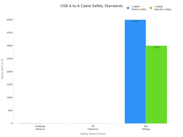
When you use a usb cable with electronic components or integrated circuits, you must watch out for safety risks. Improper connections can cause serious problems. Devices may catch fire if you use faulty or counterfeit cables. Some devices can become irreparable after using untested cables. You should always check for safety certifications before using any usb cable.
| Requirement | Condition | Distance (mm) | Test Voltage (V) |
|---|---|---|---|
| 2 MOPP | Patient Safety | 8 mm CD, 5 mm AC | 4000 V |
| 2 MOOP | Operator Safety | 5 mm CD, 4 mm AC | 3000 V |
These standards help protect both users and sensitive equipment. The universal serial bus standard also sets rules for safe operation.
Best Practices
You can keep your projects safe by following best practices. Always use usb cables with proper certifications. Look for UL, CE, RoHS, or USB-IF marks on the packaging.
| Certification | Description |
|---|---|
| UL | Ensures safety and quality in cable construction. Look for UL2725 or UL20276. |
| CE | Basic safety and performance for EU products. |
| RoHS | Limits hazardous substances for environmental safety. |
| USB-IF | Allows use of the USB logo after compliance. |
When you solder or handle usb cables, follow these safety guidelines:
- Inspect your soldering iron before use.
- Use grounded outlets and fire-resistant surfaces.
- Wear eye protection and gloves.
- Wash your hands after soldering.
- Collect waste in labeled containers.
Tip: Always know where your fire extinguisher is before you start working.
Soldering Tips
Good soldering keeps your usb connections reliable. Mistakes can damage your electronic components or integrated circuits. You can avoid common errors by using these tips:
- Use a microscope for precise soldering.
- Provide strain relief to prevent wire damage.
- Pre-align wires with a jig and secure them with tape.
- Hold wires with tweezers and keep your soldering iron on its stand when not in use.
- Use lead-free solder and control fumes with extraction systems.
If you follow these steps, you will build safer and more reliable usb connections for your projects.
Troubleshooting USB Pinout
When you work with electronic components and integrated circuits, you may face problems with the usb pinout. Knowing how to spot and fix these issues helps you keep your circuits running smoothly. This section gives you practical steps for troubleshooting for usb pinouts.
Wiring Issues
Wiring problems are common when dealing with the usb pinout in your projects. You might see these issues:
- Device not recognized: Your computer does not detect the connected component. This often happens because of a bad usb pinout or a driver problem.
- Device not receiving power: If the VBUS or GND pins in the usb pinout are not connected right, your circuit will not power up.
- Data transfer issues: Damaged cables or loose D+ and D- pins in the usb pinout can stop data from moving between your devices.
You should always check the usb pinout for correct connections before using your cable with any integrated circuit.
Connection Problems
Connection problems with the usb pinout can slow down your work. Try these steps to find the cause:
- Make sure the usb cable is firmly in both ports.
- Reboot your devices to clear software glitches.
- Clean dust from the usb ports to keep a good connection.
- Test your usb device on another computer or port.
If you still have trouble, look at the usb pinout to see if any pins are bent or broken. Sometimes, a faulty usb pinout can cause your electronic components to fail.
Solutions
You can solve most usb pinout problems with a few simple steps:
- Inspect your usb cable for damage. Replace it if you see any cuts or breaks.
- Try a different usb port to check if the port works.
- Check your device settings for the right usb configuration.
- Make sure your power supply matches your circuit’s needs.
- Update your device drivers from the manufacturer’s website.
- Test your usb device with another computer to isolate the issue.
For advanced troubleshooting for usb pinouts, use diagnostic tools. Power detectors and multimeters help you test continuity, resistance, and voltage in the usb pinout. The Advanced Cable Tester v2 checks pin continuity and signal integrity, giving you a clear view of your cable’s quality.
The Advanced Cable Tester v2 performs a Pin Continuity Test and a Signal Integrity Test, showing you how well your usb pinout works for high-speed data.
You can also follow these steps with a multimeter:
- Set your multimeter to continuity mode.
- Identify the color-coded wires in the usb pinout.
- Use the probes to test for breaks.
- Measure resistance to check wire health.
- Check voltage to confirm power delivery.
By following these steps, you keep your universal serial bus circuits safe and reliable. Always double-check your usb pinout before connecting sensitive integrated circuits.
Pinout Quick Reference
Summary Table
When you work with electronic components or integrated circuits, you often need a quick way to check the usb pinout. This summary table gives you the most important details for the usb a to usb a connection. You can use it to match each pin to its function and avoid mistakes in your projects.
| Pin Number | Signal | Description |
|---|---|---|
| 1 | VCC | +5V |
| 2 | D- | Data - |
| 3 | D+ | Data + |
| 4 | GND | Ground |
You see these four pins in every standard usb a to usb a cable. Pin 1 supplies power to your circuit. Pin 4 connects to ground. Pins 2 and 3 handle data transfer between your devices. This simple pinout helps you connect microcontrollers, sensors, and other integrated circuits safely.
Tip: Always double-check the pinout before you solder or connect a usb cable to your electronic components. A wrong connection can damage your circuit.
If you need more details or diagrams, you can find reliable information on the EDN website. This site offers clear usb pinout diagrams and wiring guides for many types of universal serial bus connectors.
- The EDN website provides trusted usb pinout diagrams.
- You can find step-by-step wiring instructions for electronic projects.
- Many engineers use these resources for integrated circuit design.
You can print this table or keep it on your workbench. It will help you save time and avoid errors when you build or repair usb connections in your electronic projects.
You now understand the usb a to usb a pinout and how it helps you connect electronic components and integrated circuits safely. Always check your wiring and use the quick reference table to avoid mistakes. If you want to learn more about the universal serial bus or need extra help, you can find many resources:
- Quick Start Guides and User Manuals
- Software Downloads and Knowledge Base articles
- Videos, Case Studies, and Application Notes
These tools help you solve problems and design better projects.
FAQ
What happens if you connect the wrong USB pinout to an integrated circuit?
You risk damaging your integrated circuit or other electronic components. Incorrect pin connections can cause short circuits, loss of data, or even permanent hardware failure. Always double-check the pinout before making any connection.
Can you use a USB A to USB A cable to transfer data between two computers?
No, you should not use a standard USB A to USB A cable for direct computer-to-computer data transfer. This can damage both computers. Use a special USB bridge cable designed for this purpose.
Why do USB 3.0 cables have more pins than USB 2.0 cables?
USB 3.0 cables include extra pins to support higher data transfer speeds and increased power delivery. These extra pins help you connect advanced electronic components and integrated circuits that need faster communication.
How do you identify the correct wire color for each USB pin?
You can use this table for quick reference:
| Pin | Color | Function |
|---|---|---|
| 1 | Red | +5V Power |
| 2 | White | Data - |
| 3 | Green | Data + |
| 4 | Black | Ground |
Always match the wire color to the correct pin for safe connections.
What tools help you test a USB pinout in your project?
You can use a multimeter to check continuity and voltage. Advanced testers like the Advanced Cable Tester v2 help you verify pin connections and signal quality. These tools help you ensure your electronic circuits work safely and reliably.