Counterfeit Electronic Component Detection: Essential Techniques for OEM Buyers and Engineers
Practical guide for buyers and engineers: Counterfeit Electronic Component Detection: Essential Techniques for OEM Buyers and Engineers. Sourcing, risk, and selection notes.

The Quiet Threat Inside Your Bill of Materials: Why Counterfeit Detection Is Now a Core Competency
When a production line stops because an FPGA doesn’t boot or a power MOSFET runs hot and fails in the field, the bill of materials becomes a suspect list. In the last three years, supply chain disruptions have pushed OEM buyers toward non-traditional channels—brokers, independent distributors, and surplus inventories—where counterfeit components thrive. The numbers are sobering. Industry estimates suggest that counterfeit semiconductors account for billions in losses annually, and the threats are no longer confined to high-reliability aerospace and defense programs. Consumer electronics, automotive modules, and industrial IoT devices all sit in the crosshairs.
What makes today’s counterfeits dangerous is their sophistication. Gone are the days of a simple blacktopped package with a mismatched logo. Modern fakes use re-balled ICs, chemically aged date codes, and cloned documentation that easily passes a cursory visual check. That’s why AGS Devices emphasizes that electrical testing is essential for mission-critical builds, especially when sourcing through brokers or during supply chain shortages. A passive component that looks genuine but carries a 30% lower capacitance or a microcontroller with a subtly altered bootloader can escape detection until the final product is in the customer’s hands.
Physical inspection alone isn’t enough. SMT Corp. points out that a high-intensity digital microscope is used to examine each component for sub-micron defects, but clues of tampering require a trained eye and precise equipment. Even then, internal anomalies—missing wire bonds, undersized die, or voids in the molding compound—remain invisible. Cyclops Electronics shows that X-ray testing can reveal these defects through the component without damaging the die wafer inside. Meanwhile, ACVISS stresses that filtering out counterfeit parts before assembly is the only way to ensure consistent performance and reduce the risk of product recalls. The message is clear: counterfeit detection is no longer a quality department afterthought—it’s a core competency that directly impacts the bottom line.
Anatomy of a Counterfeit: From Blacktopping to Re-balled ICs and How to Spot Them
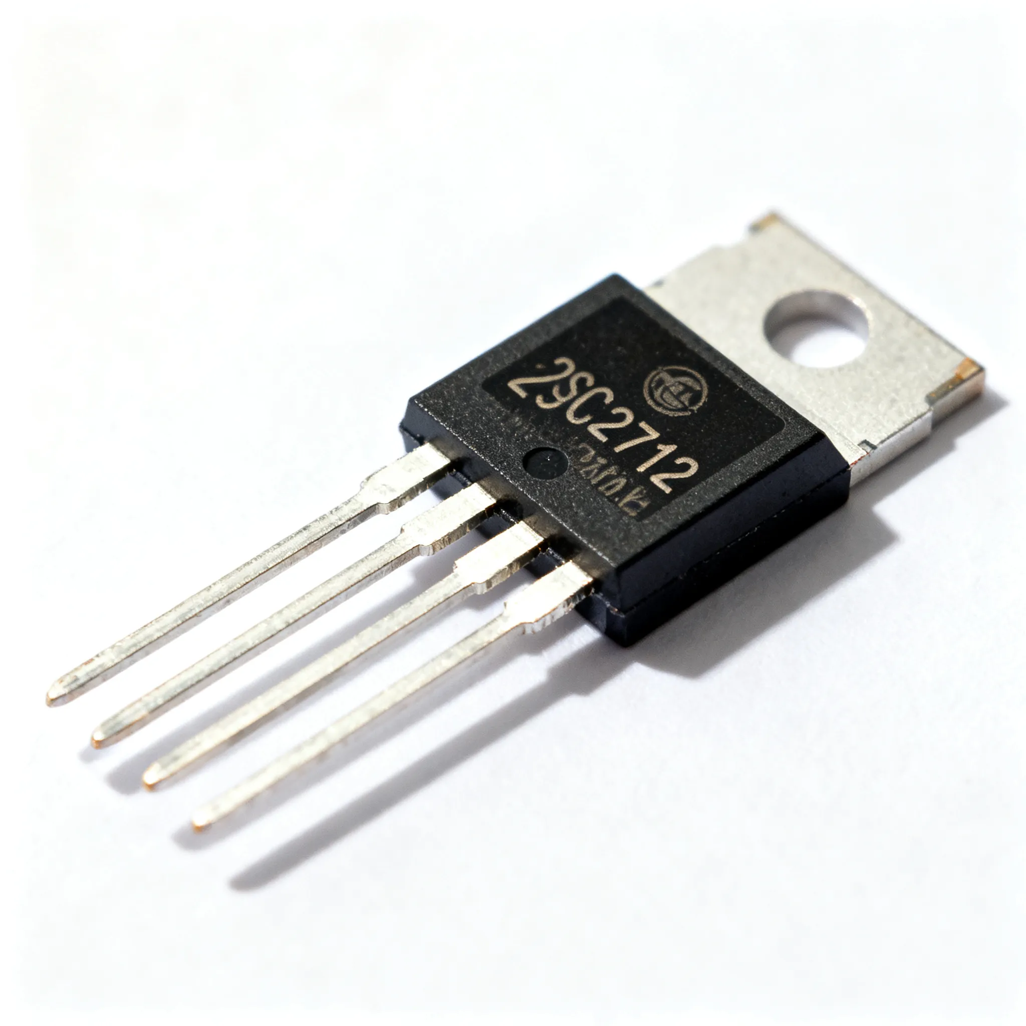
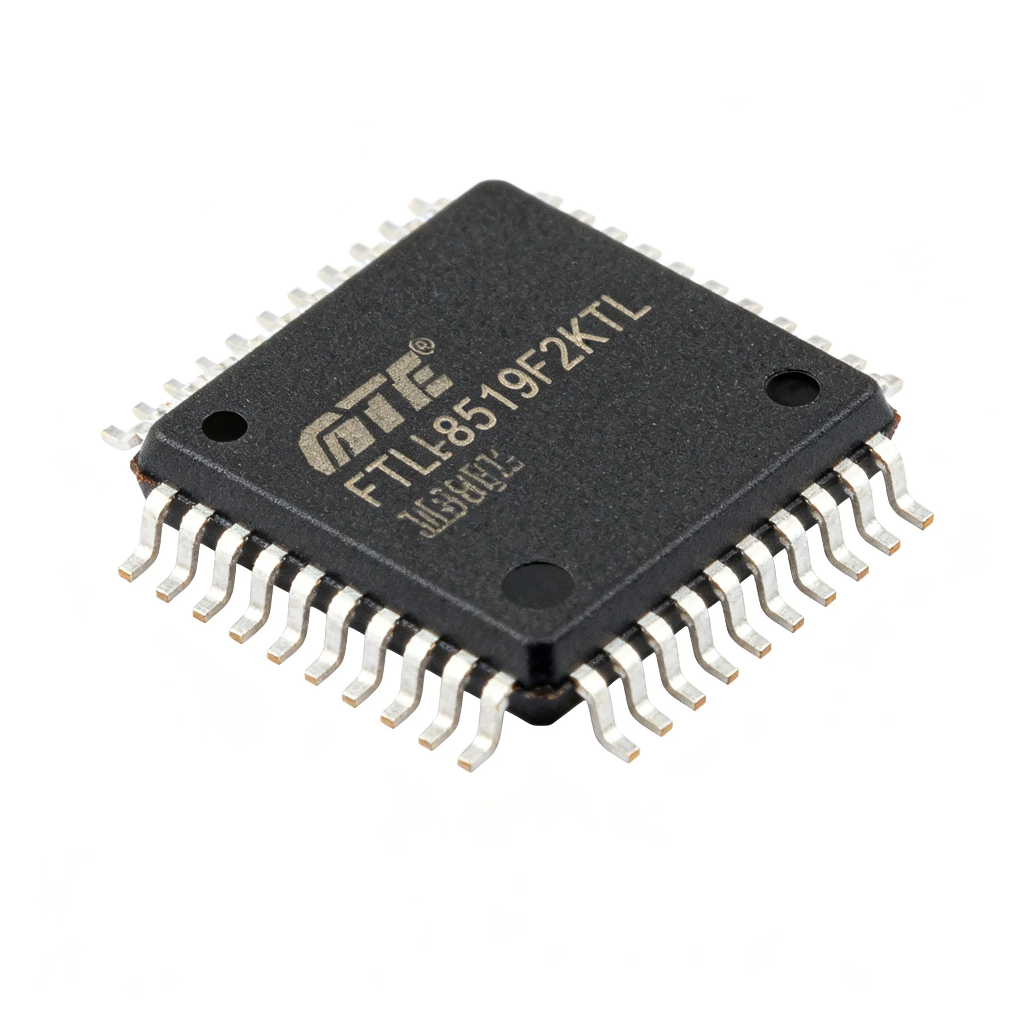
To build a reliable detection workflow, you first need to understand what you’re looking for. Counterfeiters use several physical alteration techniques that leave telltale signatures, but only if you know where to look. The most common methods include blacktopping, sanding, re-marking, and re-balling. Proto Express explains that blacktopping is a coating applied to cover the original part number after sanding away the authentic marking. An acetone test quickly reveals the ruse: if the coating dissolves or smears, the part is almost certainly counterfeit. Sanding leaves microscratches that are visible under magnification, and re-marked parts often show inconsistencies in font, character size, or indentation depth compared to a known genuine sample.
Re-balled ICs—where the original solder balls are removed and replaced to mimic a newer or higher-grade package—are trickier. They often pass electrical check at room temperature but fail under thermal cycling because the intermetallic layer is compromised. Suntsu highlights red flags such as excessive or uneven glue application, which can signal repackaging, and stresses the importance of datasheet verification: always compare the component’s physical dimensions and markings to the manufacturer’s official datasheet. Even a 0.1 mm discrepancy in package thickness can indicate sanding.
AERI recommends starting with the simplest necessary tools. You’ll need ESD-safe handling equipment, a quality microscope, and a disciplined process. A systematic approach, like the Vyrian 10-point inspection framework, helps ensure no step is skipped. The following checklist outlines a practical layered inspection sequence that any incoming QC station can adopt:
- Packaging and documentation check: Examine the outer packaging for tampering, mismatched labels, and inconsistent date codes. Verify the Certificate of Conformance against the manufacturer’s lot traceability system.
- Visual inspection at low magnification (10–40x): Look for bent leads, oxidation, scratches, and signs of re-tinning. Check for excess glue or irregular mold marks.
- High-magnification microscopy (100–200x): Inspect the component surface for sanding patterns, blacktopping edges, and laser marking quality. Compare font, texture, and pin-1 indicators with a golden sample.
- Solvent test: Apply acetone or a similar solvent to the marking area. If the coating dissolves or the mark becomes illegible, the part is likely sanded and re-marked.
- Electrical characterization: Use a multimeter, LCR meter, or curve tracer to verify basic parameters. For active parts, perform a functional test at the board level or with a dedicated test fixture, comparing results to datasheet specifications.
The table below summarizes the most common detection techniques, what they expose, and the typical equipment required. This map helps you select the right combination for your risk profile and part complexity.
| Detection Method | What It Uncovers | Typical Equipment | Best Applied To |
|---|---|---|---|
| Visual Inspection | Surface defects, re-marking, package damage, lead condition | Digital microscope (20–200x), ring light | All incoming components |
| Acetone / Solvent Test | Blacktopping, sanded and re-coated markings | Acetone, cotton swabs, fume hood | ICs with suspicious marking texture |
| X-ray Inspection | Internal wire bonds, die size, lead-frame integrity, missing bonds | Real-time X-ray system | BGAs, QFNs, and high-value ICs |
| Scanning Acoustic Microscopy (SAM) | Delamination, voids, cracks in die-attach or mold compound | Scanning acoustic microscope | High-reliability, moisture-sensitive parts |
| Electrical Testing | Functional deviation, out-of-spec resistance/capacitance, timing failures | Curve tracer, LCR meter, ATE | Active components, mission-critical builds |
This layered approach works because counterfeiters rarely get every detail right. A part that passes visual inspection may still fail an acetone test; one that passes both may show internal wire bond anomalies under X-ray. The cost of a multi-stage inspection station is trivial compared to the cost of a field failure or a full recall.
Weighing Non-Destructive Testing Methods: X-Ray, SAM, and Visual Inspection Under the Microscope
When you’re dealing with high-value or safety-critical components, destructive testing isn’t an option for every part. Non-destructive testing (NDT) methods allow you to screen the entire lot without consuming samples. The three most common NDT techniques—digital microscopy, X-ray imaging, and Scanning Acoustic Microscopy (SAM)—each have distinct strengths and limitations. Proto Express notes that electrical testing, while often destructive to the component (or requiring a test socket), remains the gold standard for functional verification, so a complete protocol often combines NDT with electrical sampling. The table below compares the three NDT workhorses.
| Comparison Metric | Digital Microscopy | X-Ray Inspection | Scanning Acoustic Microscopy (SAM) | Selection Criteria & Failure Boundary |
|---|---|---|---|---|
| Detection Capability | External surface anomalies, marking quality, lead co-planarity | Internal wire bonds, die size, lead-frame voids, counterfeits with mismatched die | Delamination, cracks, voids in molding compound, die-attach integrity | Choose based on internal vs. external failure mode; microscopy for surface, X-ray for structure, SAM for interfaces |
| Speed per Component | 2–5 minutes (manual), faster with automated optical inspection | 30 seconds to 2 minutes per part, depending on resolution | 1–3 minutes per part, batch scanning possible | Microscopy is fastest for first-pass screening; X-ray and SAM are slower but necessary for high-value lots |
| Cost of Equipment | $2,000–$15,000 (high-quality digital microscope with measurement software) | $50,000–$300,000 (real-time X-ray system) | $100,000–$400,000 (refurbished units available for less) | Budget often dictates whether X-ray/SAM is done in-house or outsourced to a test lab |
| Typical Use Case | Incoming inspection of all parts; first-line screening for broker-sourced components | BGA, QFN, and high-density packages; verification of die authenticity | High-reliability electronics, moisture-sensitive devices, and parts exposed to reflow stress | Use microscopy for 100% incoming; reserve X-ray and SAM for suspect lots or safety-critical end products |
Sensible Micro points out that it is much easier to counterfeit an electronic part’s exterior than its interior, which is why X-ray inspection is so useful for detecting discrepancies when compared to manufacturer specifications or a golden sample. ACVISS adds that SAM technology is particularly effective at detecting internal modifications that X-ray might miss, such as voids from rework or delamination between the die and mold compound. ALTER Technology reinforces that counterfeit risk often requires a combination of documentary, physical, and electrical verification techniques, and no single NDT method can guarantee authenticity.
In practice, many OEMs and contract manufacturers adopt a tiered strategy: 100% visual inspection under a digital microscope for all broker-sourced parts, X-ray sampling per AS6081 risk levels for high-density packages, and SAM for components destined for harsh environments or long-life systems. This keeps costs manageable while dramatically reducing the chance of a counterfeit slipping through.
When Standards Become Your Shield: Applying AS6081 and IDEA-STD-1010 to Your Inspection Workflow
Ad-hoc inspection is better than nothing, but it’s impossible to defend during a customer audit or a failure investigation. Industry standards transform counterfeit detection from a subjective art into a repeatable, defensible process. The two most relevant documents for OEM buyers and engineers are AS6081, the SAE standard for counterfeit electronic parts avoidance, and IDEA-STD-1010, the visual inspection standard for electronic components. Vyrian’s 10-point inspection guide aligns closely with both, illustrating how these standards can be operationalized.
AS6081 was originally developed for distributors but is now widely adopted by OEMs to qualify third-party test labs and set incoming inspection requirements. It defines a risk-based sampling plan: lots are classified by the likelihood of containing counterfeits (based on source, part type, and history), and testing is ramped up accordingly. For example, a lot of FPGA chips from a non-authorized broker would trigger a higher inspection level than a lot of passives from a trusted independent distributor. The standard also mandates a test plan that includes external visual inspection, solderability testing, X-ray inspection, and electrical verification, with acceptance criteria tied to sample size and AQL (Acceptable Quality Limit).
IDEA-STD-1010, on the other hand, is a pure visual inspection standard. It defines accept/reject criteria for external attributes such as marking permanency, lead condition, package integrity, and dimensions. It also provides guidance on internal visual inspection after decapsulation, though destructive analysis is typically reserved for a small sample. The standard classifies defects into categories (e.g., major, minor) and provides photographic examples, making it an excellent training tool for incoming QC staff.
The table below contrasts the scope and application of the two standards, helping you decide which to reference in your quality documents and supplier agreements.
| Parameter | AS6081 | IDEA-STD-1010 | Practical Implication |
|---|---|---|---|
| Primary Focus | Counterfeit detection and avoidance process | Visual inspection criteria for electronic components | AS6081 defines the “what and when”; IDEA-STD-1010 defines the “how” for visual checks |
| Scope | Risk-based sampling, test plan, documentation, and traceability for the supply chain | External and internal visual attributes, marking quality, package integrity | Use AS6081 to structure your overall program; use IDEA-STD-1010 to train inspectors and set specific pass/fail limits |
| Sampling Methodology | Yes, based on lot risk classification and AQL tables | Not explicitly defined; typically used for 100% visual or sample inspection as per organizational policy | AS6081’s sampling plan is essential for managing cost while maintaining statistical confidence |
| Documentation Requirements | Extensive: chain-of-custody, test reports, photographs, and inspection records | Inspection report with defect classification and disposition | ALTER Technology emphasizes that chain-of-custody review is a critical documentary verification step that AS6081 codifies |
| Typical User | Distributors, test labs, and OEMs qualifying suppliers | Incoming quality control, contract manufacturers, and failure analysis labs | Many OEMs require their CM to adhere to both: AS6081 for process control and IDEA-STD-1010 for detailed visual inspection |
Integrating these standards into your workflow doesn’t have to be burdensome. Start by requiring AS6081 compliance from any third-party test lab you use, and apply IDEA-STD-1010 training to your in-house inspection team. For broker-sourced parts, make a full AS6081 test report (including X-ray and electrical results) a condition of acceptance. Over time, this creates an audit trail that protects your company and gives you leverage with suppliers.
Counterfeit Detection Questions Engineers and Buyers Actually Ask
Q: How can I tell if a part is a factory rework rather than a counterfeit?
A: Factory reworks often leave behind residual flux, inconsistent solder ball shapes, or non-original date codes that are applied with a manufacturer’s approved rework label. A genuine rework will follow a traceable process and typically carries a visible rework mark or label. Counterfeit parts, in contrast, show blacktopping, sanding marks, or inconsistent indentation depth. An acetone test (as described by Proto Express) will quickly reveal a re-coated surface. Always compare suspect parts to a known golden sample and verify the lot history with the original manufacturer.
Q: What is the minimum equipment needed to start a basic counterfeit detection station?
A: You’ll need ESD-safe handling tools, a high-quality digital microscope with 20–200x magnification, a calibrated multimeter and LCR meter, acetone and cotton swabs for solvent testing, and access to official manufacturer datasheets. AERI notes that a microscope is the most essential tool. A digital camera to document anomalies and a basic soldering station for removing suspect parts from tape or tray are also recommended. This setup can be assembled for under $5,000 and will catch the majority of common counterfeits.
Q: When should I use X-ray inspection instead of Scanning Acoustic Microscopy (SAM)?
A: X-ray is ideal for checking internal bond wires, die size, and lead-frame integrity, especially in packages with opaque molding. SAM excels at detecting delamination, cracks, and voids in the die-attach or molding compound. Use X-ray for structural anomalies and SAM for interface integrity. Sensible Micro highlights X-ray’s ability to compare internal features against a golden sample, while ACVISS points out that SAM can spot internal modifications X-ray might miss. On high-risk lots, the two methods are often complementary.
Q: Can I rely on authorized distributors to completely avoid counterfeit parts?
A: Authorized distributors remain the safest channel, but counterfeits can still enter through returns, mix-ups, or grey-market infiltration. Even with franchised sources, it pays to perform basic visual and documentation checks on high-value or safety-critical components. The risk is orders of magnitude lower, but zero risk is never guaranteed. For absolute certainty, add a sample-based X-ray or electrical test for parts going into life-safety or mission-critical applications.
Q: Which documentation is most frequently forged by counterfeiters?
A: Certificates of Conformance (CoCs) and lot traceability records are the most commonly forged. Counterfeiters often alter date codes, country of origin, or manufacturer logos on labels. ALTER Technology stresses that documentary verification must include a chain-of-custody review. Always cross-check CoCs with the original manufacturer’s test reports and inspect packaging for tamper-evident seals. Anomalies like mismatched font or a missing hologram are immediate red flags.
Q: How do AS6081 and IDEA-STD-1010 differ in practice?
A: AS6081 is a process standard tailored for distributors and test labs, providing a risk-based sampling plan and a comprehensive test protocol for counterfeit detection. IDEA-STD-1010 is a visual inspection standard that defines accept/reject criteria for external and internal attributes. In practice, many OEMs require their contract manufacturers to adhere to both: AS6081 for the overall detection process and IDEA-STD-1010 for the detailed inspection of each component. Together, they create a defensible framework that can be audited and continuously improved.
No matter how thorough your detection setup, your strongest defense is a proactive procurement strategy. Combining a multi-layered inspection approach with intelligent sourcing—such as using a platform that offers mixed BOM flexibility and low minimum order quantities—can help you avoid the broker channel entirely for many components. IC-Online provides access to a wide range of genuine parts with flexible MOQs, making it easier to fill gaps in your bill of materials without resorting to risky sources. When you do need to verify parts from secondary markets, the techniques and standards discussed here will give you the confidence to keep your production line running and your products safe.
References & Further Reading
- AGS Devices – Counterfeit Components: Risks, Detection, and Avoiding Them
- SMT Corp. – Counterfeit Electronic Component Detection
- ACVISS – The Rising Threat of Counterfeit Electronic Components And How to Detect Them
- Cyclops Electronics – Counterfeit Electronic Component Detection
- Proto Express – 5 Attributes to Detect Counterfeit Electronic Components
- Sensible Micro – How To Identify Counterfeit Electronic Components
- ALTER Technology – Counterfeit Electronic Component Detection
- AERI – Counterfeit Electronic Component Detection
- Vyrian – How to Identify Counterfeit Electronic Components: 10-Point Inspection Guide
- Suntsu – Counterfeit Component Detection: A Guide to Visual Inspection
- IC-Online – Electronic Component Sourcing Platform