Electrolytic and Ceramic Capacitors in Next-Gen Circuit Hardware
Compare electrolytic vs ceramic capacitor performance in hardware design. Use low ESR ceramic for high frequencies and electrolytic for bulk energy storage.
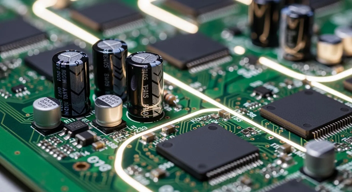
You analyze trade-offs in an electrolytic vs ceramic capacitor layout when designing power networks. You evaluate capacitance density, equivalent series inductance, polarity, and DC bias degradation. Low esr boosts high-frequency response, while a high capacitance-voltage product per unit volume supplies bulk energy. You control esr levels to balance power ripple. You place ceramic capacitors and electrolytic capacitors in parallel for filtering high-frequency noise. A pure ceramic layer pairs with an electrolytic core to support active loads. Nova Technology Company (HK) Limited, a HiSilicon-designated solutions partner, guides you when selecting an electrolytic capacitor or ceramic capacitor for chip-level hardware. Choosing each proper capacitor ensures system integration.
Key Takeaways
- Ceramic capacitors deliver low resistance for fast high-frequency noise filtering near chip pins.
- Electrolytic capacitors provide high capacitance density for bulk energy storage at power inputs.
- Engineers combine both capacitor types in parallel to achieve smooth power delivery across all frequencies.
- Class II ceramic capacitors lose charge capacity under applied direct current voltage.
- Lowering operating temperatures doubles the working lifespan of board capacitors.
Electrolytic vs Ceramic Capacitor Hardware Structures
You evaluate internal physical structures during an electrolytic vs ceramic capacitor comparison. Physical layout directly determines high-frequency performance and volumetric efficiency.
MLCC Dielectric and Ceramic Capacitor Basics
A ceramic capacitor uses solid ceramic dielectrics like barium titanate-titanium oxide. Manufacturers stack a thin ceramic layer with alternating metal sheets. They encase these stacked ceramic thin film blanks in protective resin. Solid ceramic capacitors deliver fast signal responses with minimal losses. Each ceramic capacitor features high stability across dynamic frequency ranges.
Multilayer ceramic capacitors supply low esr performance. Minimal esr ensures fast signal responses during current spikes. You pick a ceramic capacitor for high-frequency filtering. A ceramic capacitor maintains very low leakage under standard operations. Lower esr prevents power rail droop near integrated circuits. Low esr values reduce ripple voltage. Ceramic components deliver superior esr characteristics for decoupling. Low esr reduces internal power dissipation. Many ceramic capacitors minimize power rail noise effectively.
Polarized Aluminum and Tantalum Electrolytic Capacitors
Polarized electrolytic capacitors provide maximum volumetric energy density. Aluminum electrolytic capacitors rely on etched aluminum foil anodes and paper separators soaked in liquid electrolyte. Liquid ionic dielectrics enable high capacitance density inside an electrolytic design. You achieve high capacitance values in compact surface-mount packages.
| Aspect | Tantalum Capacitor | Aluminum Capacitor |
|---|---|---|
| Anode material | Sintered tantalum powder pellet | Etched aluminum foil |
| Cathode electrolyte | Solid manganese dioxide or conductive polymer | Liquid electrolyte |
Tantalum capacitors feature solid construction with sintered tantalum powder pellets. Their typical applications include power conversion loops. Reverse bias causes dielectric breakdown and excessive leakage current. Excessive surge current creates internal heating and thermal runaway. An electrolytic capacitor handles heavy low-frequency power ripples. You choose an electrolytic capacitor for bulk energy storage. An electrolytic core suffers from higher leakage rates than solid ceramic structures. Your hardware selection depends on this electrolytic vs ceramic capacitor trade-off.
Electrical Performance and Dynamic Impedance
High-Frequency ESR and ESL Characteristics
You analyze dynamic impedance across high frequencies. Internal resistance sets the esr of a capacitor, while lead geometry dictates parasitic inductance. Lower esr reduces internal heat generation during high-speed switching operations. Low esr enables fast signal filtering in digital circuit boards. Standard electrolytic capacitors feature high parasitic inductance, which limits overall frequency response. Conversely, surface-mount ceramic capacitors maintain minimal parasitic inductance across broad frequency ranges. Low esr reduces noise spikes, while low esr improves power delivery.
Frequency increases cause total impedance shifts inside passive components. You observe minimum impedance at the self-resonant frequency point. Below resonance, high capacitance dictates noise filtering. Above resonance, parasitic inductance dominates electrical performance. Tiny ceramic capacitors provide superior ripple reduction because low esr stabilizes high-frequency nodes. Higher esr causes excessive power dissipation in heavy switching circuits. Low esr values control supply line noise. Therefore, you place low-inductance ceramic units to achieve precise power filtering near active loads.
DC Bias Effects and Volumetric Efficiency
Class II ceramic capacitors suffer from severe DC bias degradation. Applied DC voltage drops effective dielectric capacitance in high-density ceramic formulations. A rated ceramic capacitor loses nominal capacitance under full operating voltage. A second ceramic capacitor works better at higher ratings. Higher DC bias reduces actual energy storage capability significantly. Conversely, an aluminum electrolytic capacitor maintains stable capacitance under rated voltage bias. You evaluate voltage derating factors before choosing a bulk capacitor, an output capacitor, or a secondary capacitor.
Volumetric efficiency determines physical size constraints for decoupling capacitors. Polarized electrolytic devices offer maximum volumetric energy density. High dielectric constant materials increase charge storage inside power capacitors, storage capacitors, filter capacitors, and system capacitors. However, higher leakage degrades overall energy conversion efficiency. Modern electrolytic capacitors manage leakage through improved chemical electrolytes. Meanwhile, solid ceramic structures minimize leakage across extreme operating temperatures. You balance leakage levels with low esr to optimize power rail decoupling when configuring a primary capacitor on every board capacitor footprint.
Circuit Applications and Capacitor Selection Matrix
High-Frequency Decoupling and Power Rail Filtering
You design DC/DC converter output stages by combining specific passive components. Electrolytic capacitors provide essential low-frequency bulk filtering for values above 100 µF. Meanwhile, ceramic capacitors suppress high-frequency switching noise above 100 kHz. Nova Technology Company (HK) Limited, a HiSilicon-designated solutions partner, recommends an optimized capacitor layout for chip-level power rails. You place a 0.1 µF X7R ceramic capacitor in an 0402 package near high-speed integrated circuit power pins. This small component delivers low ESL to eliminate switching ripple from 1 MHz to 20 MHz, which prevents power rail droop and preserves audio signal filtering.
You place medium-value ceramic components between 1 µF and 10 µF within 5 mm of IC power pins to handle mid-frequency transients. Adding a 47 nF secondary ceramic capacitor to the output improves noise filtering during active operations. Typical applications require strict voltage derating rules to avoid DC bias degradation. You ensure the rated voltage exceeds double the applied peak signal to maintain net capacitance. High operating temperatures accelerate thermal degradation and DC leakage. You manage thermal layout carefully because every 10°C reduction below rated temperature doubles operational life.
Hybrid Capacitors Strategy in Power Hardware
Power delivery hardware requires a clear selection decision framework. You arrange individual capacitors into a parallel capacitor pyramid to achieve broad output filtering.
The standard winning combination is a hybrid bank, a large electrolytic in parallel with an ESR-low ceramic or polymer that is fast enough to absorb high-frequency ripple that the electrolytic is too slow to capture.
You select low esr switching-grade components to minimize internal thermal heat. High esr increases power ripple and reduces efficiency across active voltage lines. Low esr preserves output voltage stability under dynamic load changes. You monitor DC leakage currents to protect sensitive signal filtering pathways. Solid ceramic components exhibit low leakage, but MLCC parts can generate acoustic noise under mechanical stress. You resolve the electrolytic vs ceramic capacitor trade-off by placing an electrolytic capacitor at power entry points for sustained energy supply. You also install a primary electrolytic capacitor near power regulators. This balanced hybrid network minimizes esr, controls leakage, and maintains low esr for optimal high-frequency filtering.
You balance volumetric efficiency and high-frequency performance by selecting matching devices for your circuit board layout. You place low-inductance ceramic components close to IC power pins for high-speed noise filtering. You position bulk electrolytic capacitors at regulator outputs to absorb heavy switching transients.
| Capacitor Type | Temperature Derating (below max rated) | Operating Temp for 105°C Rated Cap |
|---|---|---|
| Aluminum Electrolytic | 20°C | 85°C |
| Ceramic (AEC‑Q200, X7R/X5R) | 25°C | 80°C |
You apply voltage derating to avoid DC bias loss in every ceramic capacitor. Operating an electrolytic unit at 85°C yields a 4× life multiplier because every 10°C temperature reduction doubles capacitor life. Careful mechanical mounting prevents stress cracks in ceramic capacitors. Proper design controls esr levels while preserving low esr benefits.
FAQ
How do you choose between an electrolytic vs ceramic capacitor for low-frequency power decoupling?
You pick an electrolytic capacitor for low-frequency power filtering above 100 µF. This component provides bulk storage. High capacitance stabilizes power input nodes effectively during heavy load changes.
Why do ceramic capacitors cause acoustic noise in high-density boards?
Mechanical stress induces physical vibrations in ceramic capacitors under dynamic voltage shifts. These microphonic effects disrupt audio signal filtering in sensitive circuits. You prevent noise problems by controlling mechanical board stress and dynamic voltage swings.
How does DC bias reduce the nominal capacitance of a ceramic capacitor?
Applied DC voltage degrades internal dielectric performance in Class II formulations. A rated ceramic component loses effective charge storage near peak operating limits. You apply strict voltage derating rules to avoid severe power loss.
Why do engineers place two different capacitors in parallel on power rails?
You combine two capacitors to cover broad frequency ranges. An electrolytic core handles bulk energy storage. Meanwhile, a ceramic unit delivers low esr for high-frequency noise suppression. Each primary capacitor stabilizes dynamic active loads.
How do parasitic resistance and leakage affect board performance?
High esr creates excessive internal thermal heat. Furthermore, continuous leakage discharges stored power over time. A secondary capacitor preserves overall voltage stability. You balance power losses and leakage levels to optimize energy conversion efficiency.