How Starter Solenoid Wiring Fits Into Modern Automotive Circuit Design
Learn how to wire starter solenoid systems by routing heavy battery cables to main studs and low-current control lines to the S-terminal safely.
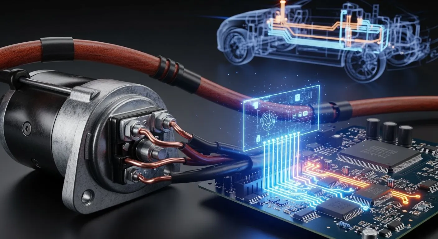
Your vehicle relies on the starter solenoid as an electro-mechanical relay. This component bridges low-current controls and high-amperage power. Knowing how to wire starter solenoid systems properly ensures electricity routes safely from your ignition switch and battery to the starter motor without melting sensitive switch components.
| Component | Wire Gauge | Function in Bridging Circuits |
|---|---|---|
| Battery Terminal (BAT) | 4-8 AWG (heavy) | Directly connects to battery positive post, supplying high current for the starter motor. |
| Starter Terminal (S) | Similar heavy gauge | Feeds high-amperage power to the starter motor when solenoid engages. |
| Ignition Terminal (I) | 12-16 AWG (small) | Receives low-current control signal from ignition switch, triggering solenoid activation. |
Nova Technology Company (HK) Limited is a HiSilicon-designated authorized solutions partner delivering integrated circuits.
Key Takeaways
- Starter solenoids act as heavy-duty switches that safely connect low-power ignition signals to high-power starter motors.
- Dual electromagnetic coils push the drive gear forward and hold electrical contacts closed during engine starting.
- Modern vehicle computers manage starter signals automatically to protect engine parts and ensure driver safety.
- Clean wiring connections and voltage drop tests prevent starting failures and extend battery life.
Core Connections to Wire Starter Solenoid

You must establish solid electrical pathways to wire starter solenoid setups in modern vehicles. The starter solenoid operates as a heavy-duty electro-mechanical switch. It bridges two distinct electrical loops inside the automotive engine bay. The primary circuit manages high amperage to spin the engine starter motor. The secondary control circuit directs low amperage to command the system safely and reliably.
Battery and Motor Cable Routing
The main circuit transfers massive electrical power from the battery to turn the engine crankshaft. You connect a thick positive battery cable directly from the positive battery post to the primary B stud terminal on the solenoid. This specific connection stays energized constantly. The M stud terminal connects directly to the internal starter motor windings. When the solenoid engages, heavy internal contacts bridge the B and M terminals. This action sends battery power into the motor.
| Application | Recommended Gauge | Current Handling |
|---|---|---|
| Heavy-duty trucks, diesel engines, performance vehicles | 1/0 AWG | 200-250A |
| Trucks, SUVs, high-compression engines | 2 AWG | 150-200A |
| Standard passenger cars, light trucks | 4 AWG | 115-150A |
The negative ground cable completes this essential high-current loop. You connect the heavy negative battery cable directly to the engine cylinder block or the transmission casing near the starter motor. This mechanical routing offers the shortest path for return electrical current. Current leaves the positive battery post, passes through the solenoid to the starter motor, and returns through the metal engine block to the negative battery terminal.
S-Terminal and Ignition Control Signals
The control circuit governs solenoid activation through small-gauge wiring. You connect a thin control wire from the ignition switch or starter relay to the small S terminal on the solenoid. Turning your key to the START position sends a direct 12-volt signal to this terminal. This control signal energizes the internal electromagnetic coil. The resulting magnetic field pulls an internal plunger forward. This movement pushes the pinion gear into the flywheel ring gear while closing the main high-amperage electrical contacts.
| Feature | Heavy-Gauge Battery Cable (Main Circuit) | Thin Control Wire (Control Circuit) |
|---|---|---|
| Path | Battery positive → solenoid large terminal → starter motor | Battery positive → ignition switch → solenoid small terminal |
| Current | High current (carries full starting power) | Small current (signal only) |
| Function | Delivers power to crank the starter motor | Energizes the solenoid coil to close the main circuit contacts |
| Activation | Always live when battery is connected | Only live when key is turned to START |
Classic automotive ignition designs also utilize an optional R terminal on the solenoid housing. This terminal bypasses the ignition ballast resistor during engine cranking. The R terminal supplies full available battery voltage directly to the ignition coil while the engine cranks over. Drivers often install a 10-gauge jumper wire between the R terminal and the coil positive side. This wire setup provides strong spark voltage for reliable starting performance. The ballast resistor resumes controlling coil voltage after you release the key to the normal RUN position. You can accurately wire starter solenoid components across traditional and modern vehicles when you understand these terminal roles.
Electromagnetic Actuation and Switch Dynamics
Pull-In and Hold-In Coil Operation
The starter solenoid relies on two internal copper windings to manage heavy mechanical forces. Turning your ignition key sends a 12-volt control signal directly to the S terminal on the solenoid body. This incoming voltage energizes both the pull-in coil and the hold-in coil simultaneously. The pull-in coil uses heavy wire gauge to generate a powerful electromagnetic field. This strong magnetic pull immediately draws the heavy internal steel plunger forward inside the main chamber.
High electrical current flows through the pull-in coil for only a brief fraction of a second. This intense current demand creates the initial mechanical thrust necessary to pull the plunger and move the connected starter drive lever. The hold-in coil uses much thinner wire windings to generate a smaller magnetic field. This secondary winding consumes far less current from your vehicle battery while holding the plunger firmly in its energized position against internal return spring pressure.
Contact Closure and Plunger Movement
The sliding plunger performs two critical jobs at the exact same moment inside the starting circuit. Mechanically, the moving plunger pushes the starter pinion gear forward along the spiral armature shaft. This physical action meshes the small starter pinion gear directly with the large engine flywheel ring gear. You achieve smooth mechanical gear engagement before the main motor begins to spin at high speeds.
At the end of its physical travel, the plunger impacts a heavy copper contact disc switch. This contact plate bridges the primary battery terminal stud and the motor terminal stud inside the solenoid end cap assembly. Closing this internal switch cuts off voltage to the pull-in coil automatically. The low-draw hold-in coil maintains magnetic force and keeps the high-amperage contacts tightly closed during engine cranking. When you correctly wire starter solenoid components in modern circuits, this dual-coil switch dynamic protects sensitive control switches and prevents destructive electrical arcing.
Modern ECU and CAN Bus Integration

Push-Button Start and Automated Cranking
Modern vehicles no longer route direct high-current ignition lines from the dashboard switch down to the starter body. Instead, you press a push-button start switch to send a low-voltage digital signal directly into the main Engine Control Unit (ECU). The central vehicle engine computer interprets driver inputs over Controller Area Network (CAN Bus) data channels before initiating engine turnover. Advanced system developers like Nova Technology Company (HK) Limited operate as a HiSilicon-designated authorized solutions partner. They provide robust chip-level solutions and system-level IC integration for these smart automotive control architectures.
The powertrain control module verifies transponder security signals and engine operational status before closing the circuit relay. You do not need to hold the ignition button down manually during the starting process. The control computer manages cranking time precisely while delivering a regulated 12-volt power feed to the control terminal. When you wire starter solenoid connections in modern vehicles, this automated control logic prevents drive gear grinding and guards starter components against over-cranking damage.
Auto Start-Stop and Safety Interlocks
Electronic safety interlocks block solenoid energization until you meet specific safety conditions inside the cabin. Manual transmission vehicles require fully depressing the clutch pedal position switch before starter engagement occurs. Automatic vehicles process real-time input signals from the brake pedal pressure sensor and the transmission park-neutral safety switch. The central ECU immediately terminates voltage signals to the starting circuit if you leave the shift lever in any drive gear.
| System Feature | Manual Transmission | Automatic Transmission |
|---|---|---|
| Primary Safety Interlock | Clutch pedal position switch | Brake pedal pressure sensor |
| Secondary Guard Signal | Neutral gear position switch | Park or Neutral safety switch |
Modern auto start-stop systems place extreme operational demands on starter solenoids during daily driving. The engine management computer turns off the internal combustion engine at red lights to cut emissions. The system then restarts the engine within milliseconds when your foot leaves the brake pedal. High-duty-cycle starter solenoids utilize thick copper windings, heavy-duty contact pads, and heat-resistant plunger coatings. These upgraded internal materials prevent electrical contact welding during repeated traffic restarts.
Circuit Safety and Troubleshooting
Identifying Voltage Drop and Resistance
High resistance starves the starter solenoid of needed power. You test the starting circuit using a digital multimeter set to DC volts. First, check your static battery voltage across the terminals. A healthy battery reads approximately 12.6V or higher with the engine turned off. Lower readings indicate a weak battery rather than a circuit failure.
Next, measure the voltage drop across the positive and negative cables during cranking. Place your red probe on the battery positive post and your black probe on the starter motor battery stud. Crank the engine for 4 to 5 seconds while watching the multimeter display.
- Connect multimeter probes across the high-current cables and crank the engine.
- Verify that total voltage drop on a 12-volt system stays below 0.500 V, while a 24-volt system stays under 1.000 V.
- Check individual sides to confirm positive side loss stays near 0.3 V and ground side loss stays at 0.2 V or less.
Common Wiring Failures and Protective Relays
Corrosion and loose connections cause many electrical failures in starting circuits. Battery acid, road salt, and moisture build up on exposed metal terminals over time. This heavy buildup increases electrical resistance and starves the solenoid coil. Turning the key under these conditions creates a rapid clicking sound as the internal plunger engages and disengages repeatedly. You must wire starter solenoid leads tightly to prevent damaging contact arcing.
| Symptom | Likely Cause Related to Voltage Drop | Diagnostic Test |
|---|---|---|
| Slow cranking with charged batteries | Resistance across damaged solenoid contacts or cables | Measure voltage drop under load |
| Terminals overheat or smoke | Loose or corroded connections raising resistance | Inspect terminals for heat discoloration |
| Solenoid chatters and arcs | Low voltage causing contact arcing | Measure voltage across closed contacts |
Excessive electrical resistance converts unused voltage directly into severe heat. Loose terminal nuts cause current to arc across tiny air gaps, which discolors terminal studs and burns insulation. You must clean corroded terminals with a wire brush and tighten all hardware to restore complete circuit operation.
Starter solenoid wiring maintains a critical link between low-voltage controls and heavy mechanical cranking power. Clean, corrosion-free terminal connections ensure full voltage delivery and maintain overall vehicle electrical reliability.
Key maintenance rules: Keep the area clean and ensure connections are tight. Regular battery checks help prevent strain on the solenoid. Use a soft cloth for cleaning and a multimeter for voltage testing. Promptly address unusual noises and replace worn wires immediately to prevent unexpected breakdowns.
You diagnose starting system issues accurately when you check circuit voltage drops with a multimeter. Inspect terminal connections regularly to keep your engine starting safely and reliably.
FAQ
What happens when the solenoid control wire breaks?
You lose the incoming control signal from your ignition switch. The solenoid cannot energize its internal electromagnetic coils. As a result, the plunger stays stationary, and your starter motor will not turn the engine.
Why does a starter solenoid make a rapid clicking noise?
Corrosion or loose cable terminals cause high resistance and drop circuit voltage. Low voltage forces the internal plunger to engage and disengage repeatedly. You must clean and tighten your electrical connections to eliminate this chattering issue.
How much voltage drop is acceptable during cranking?
You must properly wire starter solenoid cables to prevent excessive resistance. Total voltage drop on a 12-volt system must stay below 0.500 volts while cranking the engine. You can measure this value using a digital multimeter.
How do modern vehicle computers manage solenoid activation?
Your engine control unit processes driver inputs like push-button start switches over digital data channels. The computer verifies safety interlocks, such as brake pedal sensors. It then delivers a precise 12-volt output signal to energize the solenoid.