J1V-U7000NL Datasheet and Pinout: Specs for Design and Sourcing
J1V-U7000NL datasheet essentials, pinout overview, key specs, and design/sourcing checks for engineers and buyers. Request a quote on IC-Online.
J1V-U7000NL Datasheet and Pinout: Specs for Design and Sourcing
Why 10GBase‑T and PoE Are Pushing RJ45 Connector Selection
Designing a 10‑Gigabit Ethernet interface that also delivers up to 90 W of PoE power is no longer a niche requirement. Enterprise switches, outdoor wireless access points, and industrial controllers now demand a single RJ45 jack that can handle four‑pair power delivery, maintain signal integrity at 500 MHz, and survive thousands of mating cycles. The CPSC recall database serves as a stark reminder that even passive connectors can carry safety notices, making it essential to verify that the magnetics and isolation barriers inside the jack meet the design budget. In this context, the choice of an integrated magnetics RJ45 jack like the J1V-U7000NL is a critical design decision that directly impacts first‑pass EMI compliance and field reliability.
Recent supply‑chain events have shown that magnetics‑integrated connectors can experience allocation sensitivity. While the J1V-U7000NL remains in active production, engineers should confirm allocation‑backed lead time through authorized distributors rather than relying on historical averages. Working with a partner like IC-Online allows you to request a quote that reflects current availability, avoiding the pitfalls of last‑minute redesigns.
Decoding the J1V-U7000NL Pinout and Electrical Specs
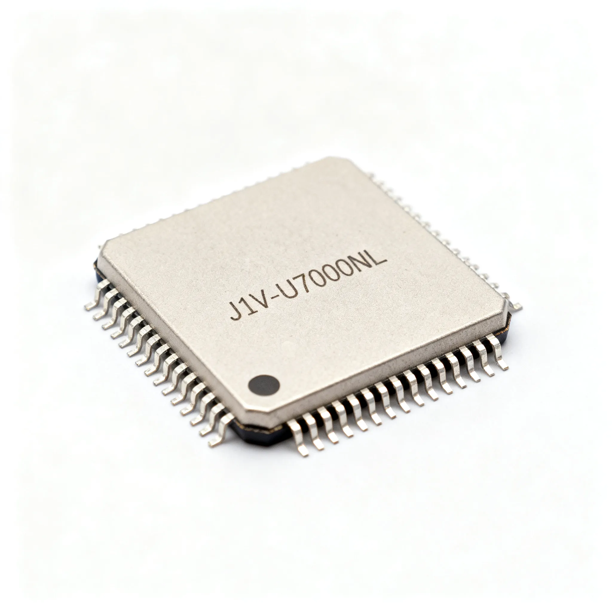
The J1V-U7000NL is a single‑port RJ45 jack with integrated magnetics, designed for 10GBase‑T, AutoMDIX, and Power over Ethernet. It comes in a through‑hole package that simplifies PCB layout for high‑speed differential pairs. The official datasheet, available from Digi‑Key and Newark, provides the detailed schematic pinout; additional U7000 series documents can be found on the Datasheet Archive.
Pinout summary: The RJ45 contacts follow the T568B pairing, with the integrated magnetics center‑tapped on all four pairs. This arrangement supports 4‑pair PoE (Type 3 and Type 4, up to 90 W). The PCB footprint includes the eight signal pins plus the shield and mounting tabs, all arranged in a standard through‑hole pattern that accepts a 1.27 mm pitch. The center taps are brought out to dedicated pins for connection to the PSE or PD controller, allowing you to inject or extract power without additional external transformers.
Key electrical specifications — use these numbers to validate your PHY vendor’s requirements:
| Parameter | Value/Range | Unit/Notes |
|---|---|---|
| Insertion loss (per pair, 1–500 MHz) | < 1.0 | dB |
| Return loss (100–500 MHz) | ≥ 10 | dB |
| Common‑mode rejection (100–500 MHz) | ≥ 30 | dB |
| Isolation voltage (hipot, primary to secondary) | 1,500 | Vrms |
| DC resistance (per channel) | ≤ 0.9 | Ω |
| PoE current rating (per pair, all four pairs active) | 600 | mA |
| Operating temperature range | 0 to +70 | °C |
| Mating durability | 750 | cycles |
These figures are taken from the Pulse Electronics datasheet. The insertion loss of less than 1 dB up to 500 MHz leaves ample margin for PCB trace losses in a typical 10GBase‑T link. The return loss of 10 dB ensures minimal signal reflection, and the common‑mode rejection of 30 dB helps suppress EMI that could otherwise couple onto the cable shield. Always cross‑check these numbers against the PHY’s acceptable limits, especially if you plan to operate the link at the maximum 100‑meter reach.
How Alternative 10G RJ45 Jacks Stack Up Against the J1V-U7000NL
When evaluating 10G magnetics jacks, you’ll find a handful of alternatives that target the same application space. The table below compares the J1V-U7000NL with two other single‑port, through‑hole jacks from Bel Fuse and TE Connectivity. The goal is to highlight differences in PoE current rating, EMI performance, and footprint, so you can decide which part best fits your design constraints.
| Comparison Metric | J1V-U7000NL (Pulse Electronics) | Bel Fuse 0825-1X1T-43-F | Selection Criteria & Failure Boundary |
|---|---|---|---|
| Data rate | 10GBase‑T | 10GBase‑T | Both support 10G, but verify insertion loss at 500 MHz in your layout. |
| PoE support | 4‑pair PoE (Type 3/4, up to 90 W) | 4‑pair PoE (Type 3/4, up to 90 W) | Ensure the PSE/PD controller can handle 600 mA per pair. |
| AutoMDIX | Yes, integrated in magnetics | Yes | Automatic crossover reduces design complexity; both parts include it. |
| Insertion loss (max, 500 MHz) | < 1.0 dB | < 1.2 dB | If your PHY demands <1.0 dB, the J1V-U7000NL gives you extra margin. |
| Return loss (min, 100–500 MHz) | 10 dB | 9 dB | Higher return loss improves signal integrity; both are acceptable for most designs. |
| Common‑mode rejection | ≥ 30 dB | ≥ 28 dB | EMI‑sensitive designs should lean toward the higher rejection spec. |
| Footprint | Through‑hole, 1.27 mm pitch | Through‑hole, 1.27 mm pitch | Mechanically similar; always verify PCB land pattern from the datasheet. |
Note: The Bel Fuse part is presented as an example for comparison; verify its current datasheet for exact specifications. The 2N7000 MOSFET datasheet guide illustrates how a rigorous pinout and spec comparison methodology applies across component types — use the same discipline when evaluating any RJ45 jack.
TE Connectivity also offers a 10G‑capable single‑port jack (e.g., 1‑2301994‑0) that integrates magnetics and PoE. Its insertion loss is typically around 1.1 dB, and it includes a metal shield with enhanced EMI grounding. If your design has a tight enclosure, the TE connector’s lower profile may be beneficial, but you’ll need to confirm that the magnetics center‑tap arrangement matches your PoE controller schematic. No single connector is a guaranteed drop‑in replacement; always verify pinout, footprint, and magnetic parameters against the manufacturer’s latest datasheet.
Where the J1V-U7000NL Fits in Real‑World Designs
The J1V-U7000NL thrives in applications where a single RJ45 port must deliver high‑speed data and significant power over a standard Cat6a cable. Here are the most common use cases:
- 10G Ethernet switches — The integrated magnetics and AutoMDIX simplify the PCB layout, allowing you to route eight differential pairs directly to the PHY without worrying about crossover detection. The 4‑pair PoE capability lets each port power a downstream device such as a Wi‑Fi 6E access point.
- IP cameras and surveillance nodes — Outdoor cameras often require 60 W or more for heaters, IR illuminators, and pan‑tilt motors. The J1V-U7000NL supports 90 W, providing headroom for future upgrades, and its robust isolation keeps the camera’s image sensor safe from ground loops.
- Wireless access points (Wi‑Fi 6E/7) — Multi‑gigabit backhaul over 10GBase‑T is becoming standard in enterprise WLANs. The jack’s insertion loss of less than 1 dB ensures the link budget is met even when the AP is located at the far end of a 100‑meter cable run.
- Industrial controllers and gateways — Factory floors demand connectors that can handle vibration, temperature swings, and EMI. The through‑hole package provides mechanical robustness, and the magnetics’ common‑mode rejection of 30 dB helps maintain data integrity in electrically noisy environments.
In each of these scenarios, the AutoMDIX feature eliminates the need for a separate crossover detection circuit, and the integrated magnetics remove the burden of sourcing and qualifying a discrete transformer module. This reduces the bill of materials and simplifies the PCB layout, which is why many engineers specify the J1V-U7000NL as their default 10G PoE jack.
Sourcing and Design Pitfalls When Using the J1V-U7000NL
Even a well‑specified connector can cause project delays if you overlook layout, procurement, or validation steps. The table below captures the most frequent pitfalls we see in design reviews and RFQ processes.
| Pitfall | Impact | Verification Method |
|---|---|---|
| Incorrect PCB footprint (land pattern does not match datasheet) | Mechanical stress, intermittent contact, assembly rework | Cross‑reference the footprint with the manufacturer’s recommended layout, available from the Digi‑Key or Newark product page. |
| Magnetics insertion loss budget exceeded when combined with long PCB traces | Link drops, BER degradation at 10G | Simulate the full channel from PHY to RJ45 and include the jack’s insertion loss (1.0 dB max). The onsemi technical documentation provides a model for how to cross‑reference magnetics specs with PHY requirements. |
| Assuming all 10G RJ45 jacks are pin‑compatible | Non‑functional board, PoE failure | Check the center‑tap configuration and pin assignment explicitly. The J1V-U7000NL brings out all four center taps; verify that your PoE controller expects this arrangement. |
| Ordering from non‑authorized sources to save cost | Risk of counterfeit or substandard magnetics, leading to field failures and safety hazards | Request a quote through IC-Online and confirm the supplier’s authorization status. Check the CPSC database for any active recalls. |
| Ignoring lead‑time fluctuations during the design phase | Production delays, forced redesign | Monitor availability on Digi‑Key and Newark and confirm allocation‑backed lead time with the distributor before finalizing the BOM. |
Procurement teams should also require a certificate of conformance and request that any test report (e.g., hipot test) be dated within 90 days of shipment. This is not a unique requirement for the J1V-U7000NL but a best practice for any magnetics component that carries isolation voltage. When you upload your BOM to IC-Online, the platform can flag such requirements and match you with suppliers who can meet them.
J1V-U7000NL: What Engineers and Buyers Ask Most
Q: What is the standard pinout of the J1V-U7000NL for 10GBase‑T and PoE?
The jack follows the T568B pairing for the RJ45 contacts, with the integrated magnetics center‑tapped on all four pairs to support 4‑pair PoE (Type 3 and Type 4, up to 90 W). The schematic pinout is detailed in the manufacturer datasheet available from Digi‑Key and Newark.
Q: Can the J1V-U7000NL be used with 1G and 2.5G Ethernet applications?
Yes, the magnetics are designed for 10GBase‑T but are backward‑compatible with slower speeds. The AutoMDIX feature automatically detects and corrects crossover, simplifying board layout regardless of the data rate. You can use the same jack for 1G, 2.5G, and 5G links without any configuration changes.
Q: What are the critical electrical specifications to verify before finalizing a design?
Key specs include insertion loss (< 1.0 dB up to 500 MHz), return loss (≥ 10 dB), common‑mode rejection, and the isolation voltage rating (typically 1.5 kV). Always compare these against the PHY vendor’s requirements. For example, if your PHY specifies a maximum insertion loss of 1.2 dB, the J1V-U7000NL gives you a comfortable margin, but you must still account for PCB trace losses.
Q: How does the J1V-U7000NL compare to other Pulse Electronics integrated magnetics jacks?
It offers a 10G‑capable design with AutoMDIX and PoE support in a single‑port through‑hole package. For higher density, Pulse’s multi‑port JXD series may be more suitable, but the J1V-U7000NL is often preferred for standalone industrial nodes where a single robust port is needed.
Q: What are the typical lead times and availability from authorized distributors?
Stock levels fluctuate; checking real‑time availability on Digi‑Key and Newark is essential. Recent supply‑chain events have affected magnetics lead times, so early procurement planning is recommended. Confirm allocation‑backed lead time with the supplier before placing a volume order.
Q: Is there any known safety recall or counterfeit concern with this connector?
No specific recalls are recorded for the J1V-U7000NL, but engineers should routinely check the CPSC database and buy only from authorized sources to avoid counterfeit parts. Requesting a RoHS and REACH compliance certificate with each shipment is a prudent step.
References & Further Reading
- J1V-U7000NL product page and datasheet – Digi‑Key
- J1V-U7000NL product page and technical support – Newark
- U7000 series datasheets – Datasheet Archive
- CPSC product safety recalls database
- 2N7000 MOSFET datasheet, pinout, and alternatives guide – Origin-IC
- Technical documentation and design guides – onsemi
- IC-Online – request a quote or upload your BOM
The J1V-U7000NL remains a solid choice for any 10G PoE design that demands proven magnetics performance and a straightforward through‑hole footprint. By verifying the pinout against your PHY, checking availability through authorized channels, and watching for the pitfalls we’ve outlined, you can avoid costly respins and keep your project on schedule. When you’re ready to source, upload your BOM to IC-Online and let the platform connect you with suppliers who can meet your delivery and quality requirements — no guesswork, no last‑minute surprises.