JYSF-08C50R Datasheet and Pinout: Specs for Design and Sourcing
JYSF-08C50R datasheet essentials, pinout overview, key specs, and design/sourcing checks for engineers and buyers. Request a quote on IC-Online.
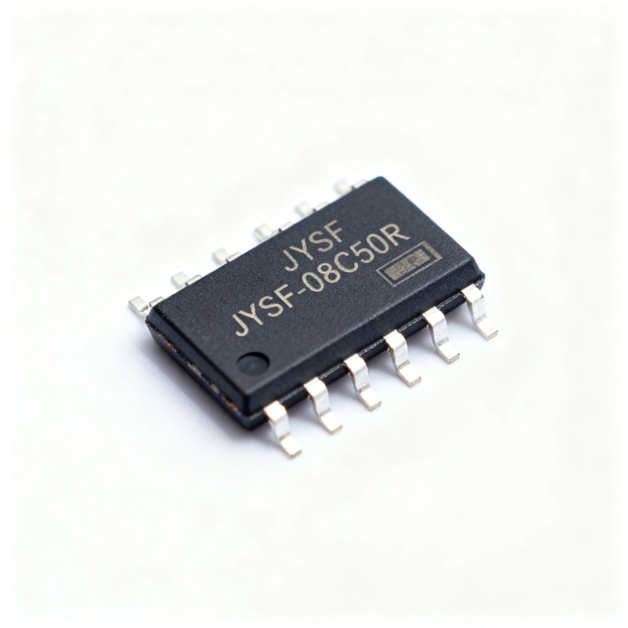
Why the JYSF-08C50R Buzzer Demands a Closer Look in Compact Designs
When you design a portable medical alarm, a Bluetooth tracker, or a smart-home sensor that must fit inside a shell no larger than a coin cell holder, every millimeter counts. Piezo transducers are often treated as commodity parts — pick the cheapest 8-mm round buzzer and move on. That approach backfires the moment the prototype produces 75 dB instead of the 85 dB the datasheet promised, or when the pin polarity assumptions don’t match the mechanical layout and the board comes back with a reversed solder joint. The JYSF-08C50R is one of those parts where reading the datasheet closely — the SPL tolerance, the pinout convention, the drive requirements — separates a clean, single-pass design from a schedule-slipping re-spin.
What makes this particular transducer worth a second look is the combination of a compact 8-mm through-hole footprint, a rated sound pressure level of at least 85 dB at 10 cm, and a straightforward 2-pin interface that operates comfortably from a 5-V rail. Engineers who have spent time sorting through supplier specifications know that not every buzzer datasheet provides the same level of detail. The onsemi technical documentation resource (onsemi technical documentation) sets a benchmark for transparency: parameter-by-parameter specs, min/max limits, and application guidance. While the JYSF-08C50R doesn’t come from that vendor, the same expectation should apply — demand clear acoustic performance data and pinout clarity before committing to a bill-of-materials line item.
For procurement professionals, this is not just an engineering concern. A poorly specified buzzer that drifts in resonant frequency across temperature or delivers inconsistent SPL at the assembly line can trigger a wave of field returns. Verifying datasheet claims against physical samples — and confirming pinout marking consistency across production lots — is a procurement gate that pays for itself quickly. The JYSF-08C50R has gained traction in designs where a simple, externally driven piezo transducer is the right acoustic solution, and the datasheet is the contract you will rely on to validate incoming material.
In the following sections we’ll break down the pinout, electrical specs, and acoustic performance as they appear in the manufacturer’s documentation, compare the component against other 8-mm piezo transducers, and walk through the design and sourcing pitfalls that can catch even experienced engineers off guard.
Pinout, Electrical Specs, and Acoustic Output — What the JYSF-08C50R Datasheet Tells You
The JYSF-08C50R is a two-terminal piezo transducer, which means it generates sound when an external AC drive signal is applied — it does not contain an internal oscillator. Before placing a trace from a microcontroller to the buzzer, you need to be certain about which pin is the positive terminal and which is ground. Pin 1 (typically the longer lead or the terminal adjacent to the polarity mark on the housing) is the positive drive input, and pin 2 is the ground return. Reversing them will not destroy the part, but SPL can degrade noticeably, and the acoustic response may shift depending on how the internal brass plate is oriented relative to the standing-wave pattern inside the enclosure.
Datasheets for piezo transducers are not always explicit about polarity conventions, and physical marking sometimes differs between production batches. A buzzer pinout guide such as the one referenced by engineers working with small acoustic components (Buzzer Pinout guide) emphasizes the importance of verifying the manufacturer’s drawing against a physical sample before finalizing the PCB footprint. Even a mirrored silkscreen symbol can cause a pick-and-place operator to insert the part backward.
The table below summarizes the Tier-A datasheet parameters you will reference repeatedly during schematic capture and layout review. These values come from the manufacturer’s published specification and represent nominal performance at 25°C unless otherwise noted.
| Parameter | Value / Range | Unit / Notes |
|---|---|---|
| Part Number | JYSF-08C50R | 8mm THT piezo transducer |
| Rated Voltage | 5 | V DC (square-wave drive) |
| Operating Voltage Range | 3 – 7 | V DC |
| Resonant Frequency | 4.0 ±0.5 | kHz |
| Sound Pressure Level (SPL) | ≥85 | dB at 10 cm, rated voltage |
| Capacitance | ~10 | nF ±30% |
| Current Consumption | ~1 | mA at rated frequency & voltage |
| Operating Temperature | -20 to +70 | °C |
| Pin Configuration | Pin 1: Positive; Pin 2: GND | Verify polarity mark on housing |
| Package / Mounting | 8-mm round; THT | Lead spacing per datasheet drawing |
Three numbers warrant immediate attention during design reviews. First, the resonant frequency tolerance of ±0.5 kHz means that if your firmware generates a fixed 4.0-kHz square wave, the actual buzzers in your production batch can have a natural resonance anywhere from 3.5 kHz to 4.5 kHz. The SPL will peak at the mechanical resonance, not at the electrical drive frequency you supply. For applications where maximum loudness is critical, consider a quick frequency-sweep calibration step in firmware, or at least measure a dozen samples to understand the distribution. Second, the ~10-nF capacitance implies that the transducer draws almost no DC current but demands a current spike each time the drive signal transitions — more on that in the design pitfalls section. Third, the SPL rating of ≥85 dB is measured at 10 cm on-axis. At 1 m, acoustic attenuation will reduce that figure significantly, so if the end product specification calls for a sound level at a distance, adjust your calculations using the inverse-square law.
The Soldering Mind resource on reading datasheets (Datasheet importance) makes a valuable point: the difference between a “typical” value and a “guaranteed minimum” is what determines whether your outgoing QC inspection passes or fails. When the datasheet states SPL ≥85 dB, treat that as the pass/fail boundary at incoming inspection, not as a typical value you might improve upon with a higher drive voltage.
Footprint accuracy is another area where assuming the datasheet drawing is correct can be costly. Verified CAD symbols and footprints — like those highlighted in the Ultra Librarian discussion of consistent component models (Ultra Librarian L298N article) — help avoid the situation where a library part has a pin-pitch error that escapes schematic review but becomes obvious at assembly. For the JYSF-08C50R, the key mechanical dimensions to verify are the pin diameter, lead spacing, and the overall diameter plus height of the brass plate; the part must fit under any lid or membrane that covers the acoustic port.
How the JYSF-08C50R Stacks Up Against Other 8mm Piezo Transducers
An 8-mm through-hole piezo buzzer may look interchangeable on a distributor’s parametric search page, but three variables drive real-world selection: minimum SPL at the design voltage, resonant frequency tolerance, and how the mounting style interacts with the enclosure acoustics. The table below compares the JYSF-08C50R against two widely referenced alternatives — the Murata PKM13EPYH and the Kingstate KPEG128 — across the parameters that matter when you are down-selecting for a production design.
| Comparison Metric | JYSF-08C50R | Murata PKM13EPYH (Reference) | Kingstate KPEG128 (Alternative) | Selection Criteria & Failure Boundary |
|---|---|---|---|---|
| Package Diameter | 8 mm, round THT | 12.5 mm, round THT | 8 mm, round THT | Board real estate; JYSF and KPEG128 fit tighter layouts |
| Rated Voltage | 5 V | 3 V (peak-to-peak) | 5 V | Rail voltage compatibility; drive stage headroom |
| Resonant Frequency | 4.0 kHz ±0.5 kHz | 4.0 kHz | 3.5 kHz ±0.5 kHz | Tone accuracy; firmware tuning range |
| SPL (Typical / Min) | ≥85 dB at 10 cm / 5 V | ≥70 dB at 10 cm / 3 Vp-p | ≥82 dB at 10 cm / 5 V | Loudness budget; confirm actual SPL at your Vcc |
| Capacitance | ~10 nF | ~12 nF | ~8.5 nF | Peak drive current; GPIO buffer requirements |
| Mounting Style | PCB through-hole | PCB through-hole | PCB through-hole with pins or SMD option | Assembly process; SMD reflow profile not needed for THT |
| Sourcing Lead-Time Sensitivity | Confirm via RFQ | Distributor-dependent; confirm allocation | Verify stock position with franchised distributors | Single-source risk assessment for each candidate |
The Murata part brings strong brand recognition and a datasheet that electrical engineers trust, but its 12.5-mm diameter and lower SPL at the rated 3-V drive level can be a challenge if your application runs from a single Li-Po cell and cannot accommodate a boost converter just for the buzzer. The Kingstate KPEG128 aligns more closely with the JYSF-08C50R in package size and voltage, though its resonant frequency sits 500 Hz lower and the SPL floor is a few decibels quieter. Neither alternative is a compatibility must be verified (package, pinout, firmware); you must evaluate pinout compatibility and physical clearance against the manufacturer’s mechanical drawing. Using a CAD library service that follows the approach described in the Ultra Librarian article (Ultra Librarian L298N article) can help you overlay 3D models of competing buzzers on your board outline without building physical prototypes.
From a sourcing perspective, the JYSF-08C50R is often considered for its value proposition in cost-sensitive consumer electronics, but the procurement team must verify allocation-backed availability through the approved supply chain. No universal “mainstream second source” exists for this exact form factor and specification, so it is wise to confirm multi-source risk through your distributor documentation early in the design phase.
Design Pitfalls and Sourcing Traps When Using JYSF-08C50R Buzzers
A piezo transducer that works perfectly on a lab bench can become a source of EMI headaches in a production enclosure, or worse, pass acoustic testing in a quiet room only to be inaudible in a noisy field environment. The following table captures the most common issues and the mitigation steps that should be part of any design review that includes the JYSF-08C50R.
| Pitfall | Recommendation | Consequence If Ignored |
|---|---|---|
| Driving directly from a GPIO without current limiting | Insert a series resistor (220 Ω typical) between GPIO and pin 1; evaluate peak current at highest Vcc | GPIO latch-up, reduced life, or SPL variation with supply voltage |
| Placing the drive transistor far from the buzzer | Keep the NPN/NFET within 10 mm of the buzzer; minimize loop area | Radiated EMI at 4 kHz harmonics; interference with analog sensor traces |
| Omitting supply decoupling at the drive stage | Add a 100-nF ceramic capacitor directly across Vcc and GND at the transistor | Voltage ripple on the rail; audible noise coupling into audio codecs |
| Assuming SPL is constant across temperature | Measure SPL at -10°C and +60°C for your enclosure; resonant frequency shifts ~ -0.2% / °C | Reduced loudness in cold-start conditions; missed alarm thresholds |
| Ignoring pin polarity in the footprint symbol | Verify pin-1 indicator matches physical marking; build a test jig for incoming QC | Intermittent acoustic output; yield loss at board-level functional test |
| Sourcing from unauthorized channels | Require traceable lot codes; perform SPL and capacitance spot-checks on first article | Counterfeit parts with lower SPL, brittle pins, and missing laser marking |
| Relying on “typical” SPL for compliance | Design to the minimum SPL spec; add acoustic margin for enclosure losses | Field returns due to insufficient sound output in end-use environment |
One point deserves a deeper dive: the datasheet may not publish a maximum current rating for the transducer itself, because the current is largely defined by the capacitive reactance and the drive waveform edge rate. Measuring the in-circuit current at the highest operating voltage and at the resonant frequency is the only way to confirm your drive circuit stays well within safe limits. A 1-mA typical current can turn into a 5-mA transient if the microcontroller’s GPIO transitions are fast and the series resistor is omitted. Budget for that margin.
Counterfeit and substandard piezo buzzers are a real sourcing headache. Genuine JYSF-08C50R components carry a consistent laser part-number marking on the brass plate or housing. Counterfeit units often exhibit lower-than-specified SPL — sometimes 75 dB instead of 85 dB — and the lead wire can be slightly thinner, making them prone to fracture during wave soldering or mechanical shock. The Soldering Mind datasheet guide (Datasheet resource) reinforces a simple discipline: always cross-reference the datasheet values against a sample lot before volume purchase, and build an incoming inspection checklist that includes SPL, capacitance, and visual marking checks.
Procurement teams should treat the JYSF-08C50R as an allocation-sensitive component. Rather than assuming a fixed lead time, confirm current allocation and shipment schedules directly with the franchised distributor or via an RFQ on IC-Online. This also creates leverage for negotiating MOQ flexibility when blending this part with other BOM lines.
JYSF-08C50R Datasheet and Sourcing Questions from Design Engineers
Q: Is the JYSF-08C50R a self-drive or external-drive buzzer?
It is an external-drive piezo transducer — it has no internal oscillator. You must provide an external AC drive signal, typically a 4-kHz square wave generated by a microcontroller timer output. A self-drive buzzer would integrate the oscillator and simply require a DC voltage; the JYSF-08C50R does not. That means you have full control over frequency, but you also shoulder the responsibility of tuning the drive waveform to match the mechanical resonance for maximum SPL.
Q: What is the resonant frequency tolerance and how does temperature affect it?
The datasheet specifies 4 kHz ±0.5 kHz at 25°C. The resonant frequency drifts with temperature at roughly –0.2% per °C relative to the room-temperature value, which translates to about –8 Hz/°C. Across a –20°C to +70°C operating range, the resonance can shift by several hundred Hertz. For applications that require a precise, stable tone — such as a medical alarm that must be recognizable against background noise — validate the frequency response across your full temperature profile and consider implementing an auto-tuning routine in firmware if the tolerance stack-up is too wide.
Q: Can I drive the JYSF-08C50R directly from a microcontroller GPIO?
Yes, with appropriate current limiting. Add a series resistor of 220 Ω between the GPIO and the positive pin of the transducer. Verify that the GPIO can source at least 1–2 mA without significant voltage droop. The pin sees a roughly 10-nF capacitive load, so peak currents during logic-level transitions will be higher than the steady-state RMS current. For higher SPL or for MCUs with weak GPIO drive strength, insert an NPN transistor or logic-level NFET as a buffer, and drive the gate/base from the GPIO through a current-limiting resistor. A small-signal transistor like a 2N3904 with a collector resistor of a few hundred ohms is often sufficient.
Q: How does sound output vary with voltage and distance?
SPL is rated at ≥85 dB with a 5-V square-wave drive measured at 10 cm. Lowering the drive voltage reduces SPL non-linearly; a halving of voltage can drop SPL by approximately 3–6 dB, depending on where the operating point sits on the transducer’s electromechanical coupling curve. Distance attenuation follows the inverse-square law: doubling distance from 10 cm to 20 cm can drop SPL by roughly 6 dB in free-field conditions. If your end product’s acoustic specification is defined at 1 m, you will need to budget for significant attenuation and either raise the drive voltage (within the 7-V maximum) or use a larger transducer.
Q: What are common sourcing issues and how can I verify genuine parts?
The primary sourcing risks are counterfeit components with lower SPL, missing or inconsistent laser part-number marking, and mechanically fragile leads that break during assembly. To verify genuine parts:
- Purchase only through authorized or franchised distributors and request a Certificate of Conformance with each shipment.
- Inspect physical marking — genuine JYSF-08C50R units should show consistent laser engraving on the brass surface or housing, not ink that can be wiped off.
- Bench-test a sample lot: measure SPL at 5 V / 10 cm using a calibrated microphone, and compare against the datasheet minimum of 85 dB.
- Measure capacitance (nominally 10 nF) at 1 kHz to catch gross material substitutions.
- Request a supplier’s batch test report that includes SPL data and frequency response curves for the specific lot being shipped.
Building an incoming QC gate around these checks is a wise investment if your product volume exceeds a few thousand units per year. The cost of a returned product due to an inaudible buzzer far outweighs the cost of a quick acoustic test at the receiving dock.
Once you have validated the datasheet parameters against your design requirements, the next step is to lock in commercial terms. Upload your bill of materials or request a quote through a platform that handles mixed-BOM sourcing with flexible minimum order quantities. The IC-Online RFQ workflow lets you consolidate multiple lines — including the JYSF-08C50R — and confirm pricing and allocation without committing to a single supplier’s inventory position.
References & Further Reading
- onsemi Technical Documentation — A reference standard for datasheet transparency and application guidance in the semiconductor and sensor industry.
- Ultra Librarian: L298N Datasheet, Pinout, and Specs — Highlights the value of verified CAD models and footprints to avoid schematic-to-layout mismatches.
- Soldering Mind: Datasheet Resource — Practical guidance on interpreting component datasheets and validating specifications against physical samples.
- Buzzer Pinout, Working, Specifications & Datasheet — A general reference for piezo buzzer pinout conventions and testing approaches.
- Piezo Buzzers on IC-Online — Browse and source piezo transducers and indicators from multiple authorized distributors.
- IC-Online RFQ Platform — Request quotes and upload mixed BOMs for the JYSF-08C50R and associated components.