What Does VSC Mean in General Electronics
The meaning of VSC in general electronics is Voltage Source Converter, a key device for power conversion. Learn how it works and its applications.

Have you noticed a vsc light on your dashboard? The meaning of vsc depends on context. In power electronics, vsc stands for Voltage Source Converter. In automotive safety, vehicle stability control is the meaning of vsc. This blog focuses on the voltage source converter. We acknowledge the automotive vsc system to avoid confusion.
You will learn how a vsc works. Pressing vsc off disables the stability control system. Driving with vsc off changes your control. The system uses electronics. Another vsc light indicates a fault. Driving without vsc requires caution. Press vsc off to disable the vsc light warning. A vsc light appears during startup. Understanding the vsc light helps diagnose issues. The vsc technology is fascinating.
This guide explains the vsc in simple terms.
Key Takeaways
- VSC stands for Voltage Source Converter, a smart device that converts DC to AC power with high efficiency and precise control.
- Rapid switching and pulse width modulation (PWM) allow VSC to adjust voltage and frequency, making it ideal for motor drives and power supplies.
- Advanced VSC designs like Modular Multilevel Converters (MMC) provide clean power, high efficiency, and fault tolerance for large-scale energy systems.
- In cars, VSC means Vehicle Stability Control, a safety system that helps prevent skids by applying brakes to individual wheels.
- A dashboard VSC light warns of faults; pressing VSC off disables the system, but you should drive with caution on slippery roads.
What Is the Meaning of VSC?

Defining Voltage Source Converter
You encounter the meaning of vsc in two distinct contexts. In power electronics, a voltage source converter acts like a smart switch. It converts direct current into alternating current and performs the reverse operation. This device controls both voltage and frequency of the output. Think of it as a sophisticated power adapter that changes the form of electricity while maintaining precise control. The switching occurs at very high speeds, often thousands of times per second. This rapid switching creates a waveform that approximates a smooth AC signal. The quality of this output depends on the switching pattern and the number of switching levels.
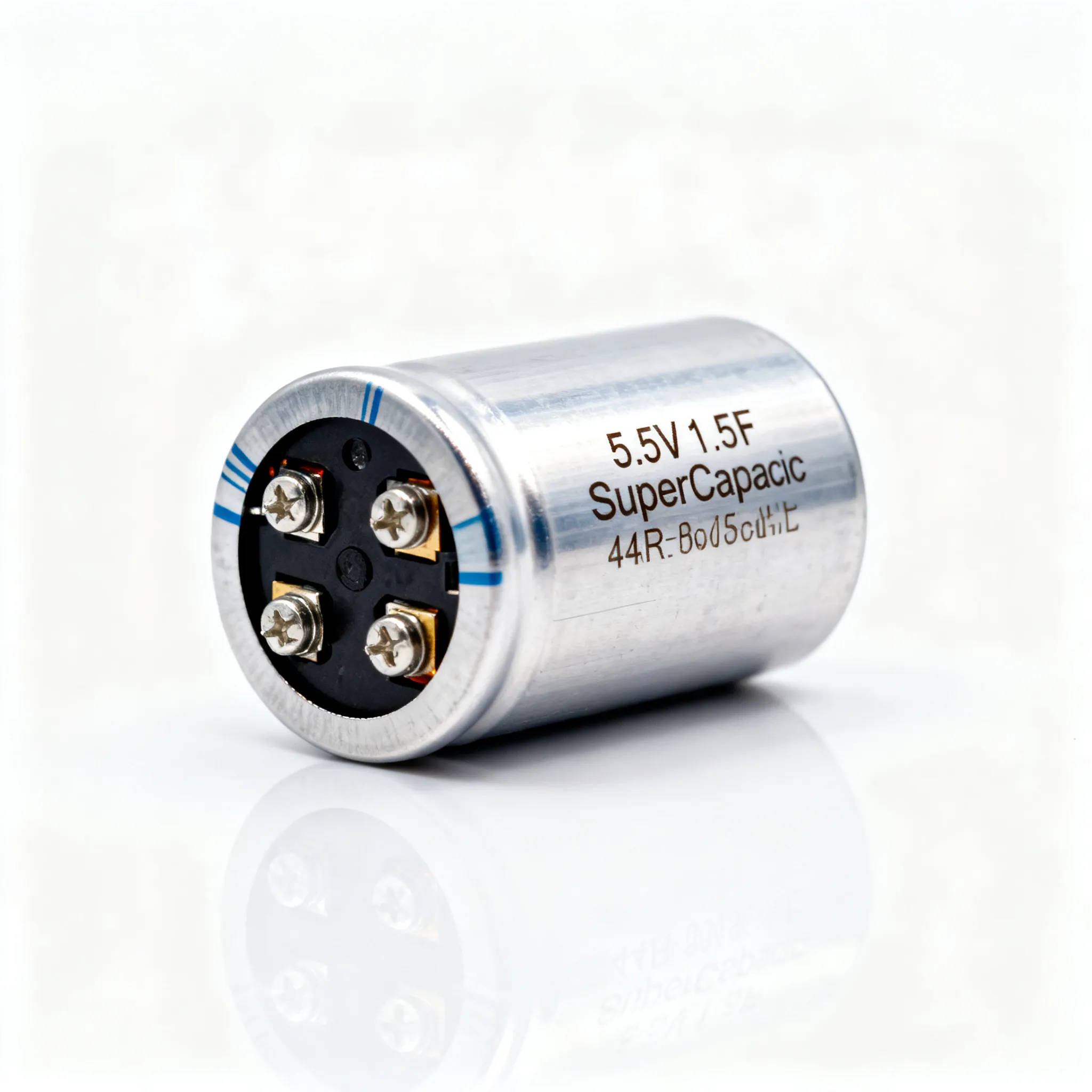
The key difference between a VSC and a current source converter lies in the DC link. A VSC uses a large capacitor connected in parallel as its main energy storage element. This capacitor maintains a constant input DC voltage. The source has negligible impedance. Only the input current changes with the load. In contrast, a CSC uses an inductor in the DC link. This inductor maintains a constant current. The voltage varies while current stays constant. These differences determine their applications. You use a VSC for purely resistive or lightly inductive loads like lighting, AC motors, and heaters. A CSC suits highly inductive loads like induction motors. The VSC is less prone to overloading and short-circuiting in these applications.
The market for VSC technology shows strong growth. The global HVDC transmission market, which relies on the converter as a core technology, reached USD 14.01 billion in 2024. Analysts project it will reach USD 22.07 billion by 2030. This represents a compound annual growth rate of 7.2%. The VSC share of technology demand stands at 54.0%. This makes VSC the dominant converter type in the industry. HVDC products account for 72.0% of HVDC applications. By 2026, the market size is expected to reach USD 24.0 billion, growing to USD 67.6 billion by 2036 at a CAGR of 10.9%. These numbers show the growing importance of VSC technology in modern power systems.
VSC vs. Vehicle Stability Control
The meaning of vsc changes completely when you enter the automotive world. In cars, VSC stands for Vehicle Stability Control. This is a safety feature that helps you keep you stable during sudden maneuvers. Several major manufacturers use this term. Toyota, Lexus, and Daihatsu all call their brand Vehicle Stability Control. Other automakers use different names. You might see electronic stability control (ESC) or vehicle skid control on other brands. Some systems integrate with a traction control system. These all serve the same basic purpose. They use sensors to detect when your vehicle starts to lose grip. The system then applies brakes to specific wheels to correct the skid.
When you see a vsc light on your dashboard, it indicates a problem. The vsc light may appear during startup for a system check. It should turn off after a few seconds. If the vsc light stays on, the system has detected a fault. The vsc light serves as your primary warning for stability issues. Pressing vsc off turns off the vsc light in some cases. Driving with vsc off changes how your vehicle handles. The system will not intervene to correct skids or loss of traction. The vsc system uses sensors and control systems to monitor your driving. It applies brakes to individual wheels to help you maintain vehicle stability. Driving without vsc requires more caution on slippery roads. The vsc system helps prevent accidents. You can press the vsc off button to disable the system when you want more control, such as driving in deep snow or mud.
This blog focuses on the power electronics meaning of VSC. The automotive VSC is a good example of electronics in action. The meaning of vsc depends entirely on your context.
How Does a VSC Work?
The Role of Switching in Power Conversion
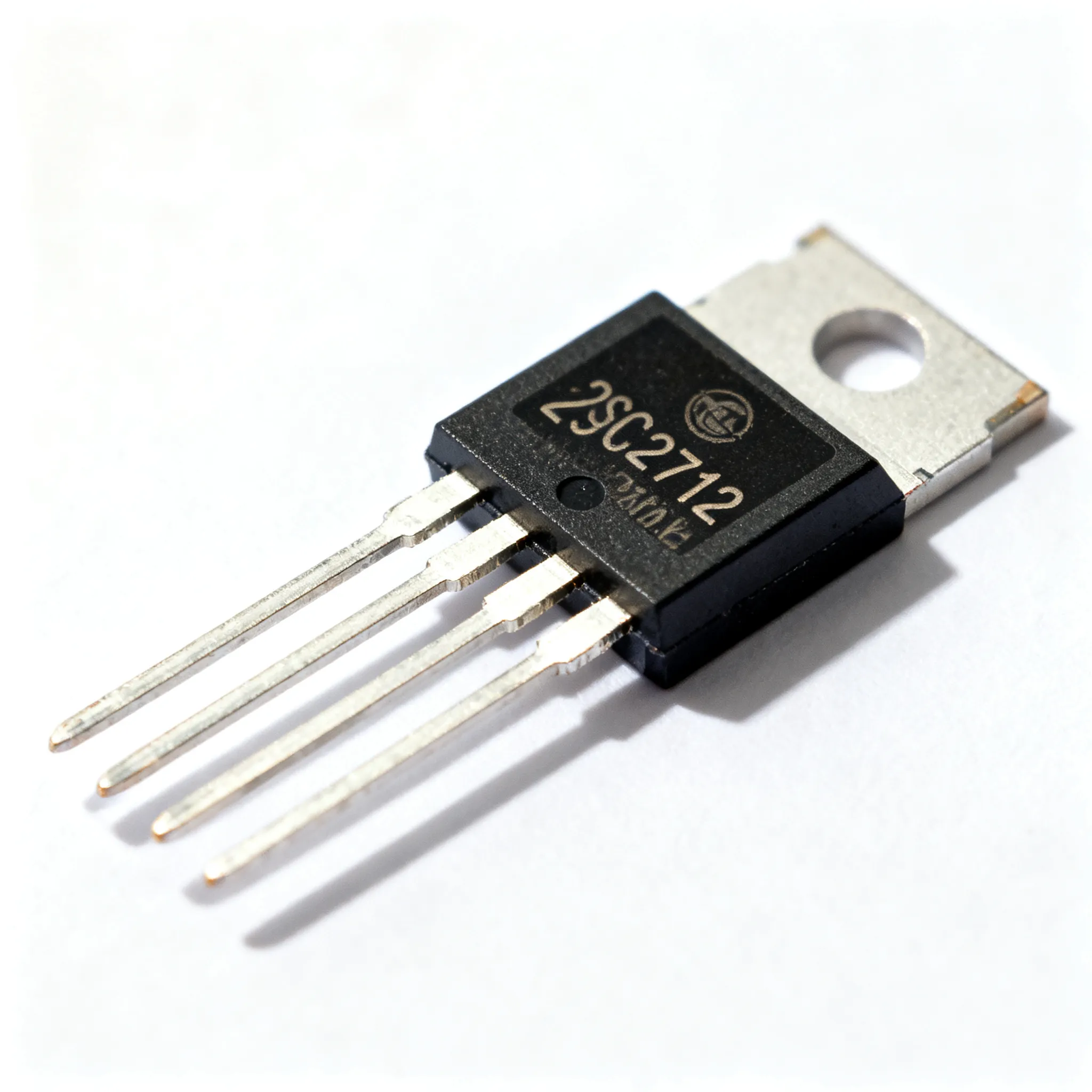
A voltage source converter operates on a simple principle: rapid switching. Inside the device, semiconductor switches called IGBTs (insulated-gate bipolar transistors) turn on and off thousands of times per second. These switches connect and disconnect the DC input from the output circuit in a precise pattern. This rapid action creates an alternating current waveform from a direct current source.
Consider a basic inverter circuit. A transformer connects to a DC input through a switch that oscillates back and forth quickly. The bi-directional current flow in the primary coil produces an alternating current signal in the secondary coils. An astable multivibrator generates a 50 Hz square wave. Power MOSFETs amplify this signal and feed it to a step-up transformer with its center tap connected to the DC supply. This arrangement forms the foundation of many power conversion systems you encounter daily.
The switching speed and pattern determine the quality of the output waveform. A simple switch creates a crude square wave. More sophisticated vsc designs use multiple switches working in sequence. Each switch contributes a portion of the output, creating a smoother approximation of a sine wave. The more switching levels you add, the cleaner the output becomes. This principle explains why multilevel converters produce higher-quality power than their simpler counterparts.
Pulse Width Modulation (PWM) for Voltage Control
Switching alone only creates a fixed waveform. To control the output voltage, the vsc uses a technique called pulse width modulation, or PWM. This method varies the duty cycle of the switches. The duty cycle represents the proportion of time each switch stays on versus off during each switching period.
Think of a dimmer switch on a household light. You rotate the knob to adjust brightness. The dimmer does not reduce the voltage directly. Instead, it rapidly turns the power on and off. Your eye perceives the average brightness. PWM works the same way. The vsc system turns the switches on and off at a fixed frequency. By changing the width of the "on" pulses, you change the average voltage delivered to the load. A wider pulse delivers more energy. A narrower pulse delivers less.
This control method proves remarkably efficient. Unlike resistive methods that waste energy as heat, PWM switches between fully on and fully off states. The switches dissipate minimal power during transitions. This efficiency makes PWM the standard approach in modern power electronics. You find it in everything from phone chargers to industrial motor drives.
The feedback loop completes the picture. Sensors measure the output voltage and current. A controller compares these measurements against the desired values. If the output drifts, the controller adjusts the PWM duty cycle to correct the error. This closed-loop system maintains precise voltage regulation despite changing loads or input variations.
The same feedback principle appears in automotive stability systems. A steering wheel position sensor and speed sensors determine your intended path. A yaw rate sensor and lateral acceleration sensor measure the vehicle's actual motion. The system compares these values. If they differ, the vsc system applies braking force to individual wheels and may reduce engine power. This corrective action generates a yaw moment that pulls the vehicle back to your intended path. The process repeats continuously, forming a closed-loop control system that maintains vehicle stability.
Types of VSC Topologies
Two-Level and Multilevel Converters
A vsc comes in several basic topologies. The simplest design uses a two-level vsc. This vsc switches between two voltage levels only. The circuit is straightforward and cost-effective. The output waveform contains significant harmonic distortion. The harmonics increase at higher power levels. You may need additional filtering to meet power quality standards. A two-level vsc struggles with compliance at high power levels.
A multilevel vsc solves these problems. This vsc type uses multiple voltage levels. The output waveform steps through several intermediate voltages. This produces a smoother sine wave. The harmonic content drops significantly. You often need less filtering equipment. A multilevel vsc works well for medium-voltage applications. The control requirements increase with more levels. More switches and circuits add complexity. The trade-off pays off in better power quality.
Modular Multilevel Converters (MMC) for High Power
The modular multilevel converter represents the most advanced topology. You find this vsc in modern high-voltage direct current systems. The MMC stacks many small submodules together. Each submodule acts as a tiny independent converter. The vsc system combines their outputs to handle extremely high voltages. This modular design offers several advantages. You can scale the system easily by adding or removing submodules. If one submodule fails, the rest continue operating. The arrangement maintains functionality with reduced capacity.
The MMC produces the cleanest output waveform. The harmonic content is inherently reduced. You comply with power quality standards more easily. The design requires minimal filtering. Each submodule switches at a lower frequency. This reduces switching losses and improves overall efficiency. The control system coordinates thousands of submodules. It balances the voltage across each module. The controller maintains precise control of the output waveform. The system monitors each submodule constantly. This topology provides stability for large-scale power transmission. The overall system achieves higher efficiency.
Your renewable energy grid applications use this technology. The modular design provides reliability and scalability. The inherent harmonic reduction simplifies design. The lower filtering requirements reduce costs.
Applications and Links to General Electronics

VSC in Power Supplies and Motor Drives
You find a VSC in variable-speed motor drives. A VSC converts fixed AC to variable-frequency AC. A VSC in a motor drive application uses vector control. This method provides a wide speed control range, minimal speed error, and fast torque response. This precision makes vector control ideal for cranes and electric traction systems. You achieve independent control of flux and torque-producing currents.
The same principles apply to power supplies. Consider a loose terminal carrying a high current. The joint resistance causes a voltage drop and power dissipation proportional to the square of the current. This explains why a loose connection becomes a fire risk at high current.
For high-power applications, the modular multilevel converter (MMC) dominates. This VSC topology stacks 76 series-connected submodules in each arm. Each submodule delivers 8.42 kV. Their series connection sums to ±320 kV. The system handles 420 MW. The MMC achieves 98.5% to 99.2% efficiency. The modular design provides fault tolerance. The system continues operating with multiple submodule failures.
VSC Light: What It Means in Automotive Electronics
When you see a vsc light on your dashboard, pay attention. This warning light indicates a problem with your stability control system. The vsc warning light tells you that the electronic stability control system has detected a fault. Toyota calls it vehicle stability control. Other brands use ESC or vehicle skid control. The function remains the same. The vsc system helps you maintain control during driving.
The vsc system uses sensors to monitor your driving. It compares your steering input with the vehicle's actual motion. If the vehicle starts skidding, the system applies brakes to individual wheels. This prevents skidding or veering off the road. The system works with the traction control system. The traction control system functions alongside the stability system. Your traction control system helps maintain grip on slippery conditions. The vsc light remains off during normal driving. A steady vsc light indicates a fault. The vsc light also appears during system startup. The vsc light should turn off after a few seconds. If the vsc light stays on, the system has detected a fault. The vsc light serves as an indicator. The vsc light is your primary warning.
You can press the vsc off button to disable the system. Press vsc off to disable the stability function. The vsc off light illuminates when you do this. Driving with vsc off gives you more control in deep snow or mud. You need more caution with vsc off active. The vsc will not intervene to correct loss of grip. Driving without vsc requires extra attention. Driving on slippery conditions requires extra care. The electronic control unit processes sensor data. This closed-loop control maintains vehicle stability. The grip sensors help detect loss of traction. The vehicle stability feature improves safety.
You now understand the vsc as a fundamental building block in power electronics. This converter enables efficient energy conversion and precise control across modern systems. The vsc system transforms how you manage power in renewable energy, motor drives, and transmission networks.
Remember the dual meaning. In automotive contexts, vsc refers to vehicle stability control. A vsc light warns you of issues with the system's sensors or other components. You should scan error codes and consult a mechanic. Driving with vsc off requires extra caution on slippery roads.
Understanding the vsc opens doors to smart grids and electric vehicles. You already grasp the basic electronics principles behind this technology.
FAQ
What does the vsc light mean on my dashboard?
The vsc light serves as a warning indicator. When it stays on, your vehicle stability system has detected a fault. The vsc warning light may also appear briefly during startup as a system check. If it remains lit, you need professional diagnosis.
Can I drive with the vsc light on?
You can drive, but you should exercise caution. The stability system will not intervene during skidding. Driving with vsc off or with a fault reduces your safety margin. The traction control system may also stop functioning. Have the system checked promptly.
How do I turn off the vsc system?
You press the vsc off button located on your dashboard. This action disables the electronic stability feature. The vsc off indicator illuminates to confirm. Use this option only for specific situations like deep snow or mud where wheel spin helps maintain grip on slippery conditions.
What is the difference between vsc and esc?
The vsc and esc refer to the same technology. Vehicle stability control is Toyota's brand name. ESC stands for electronic stability control, the generic term used by most manufacturers. Both systems provide the same control function: they apply brakes to individual wheels to prevent loss of control during cornering.