

MS74-4R7NT Datasheet and Pinout: Specs for Design and Sourcing
MS74-4R7NT datasheet essentials, pinout overview, key specs, and design/sourcing checks for engineers and buyers. Request a quote on IC-Online.
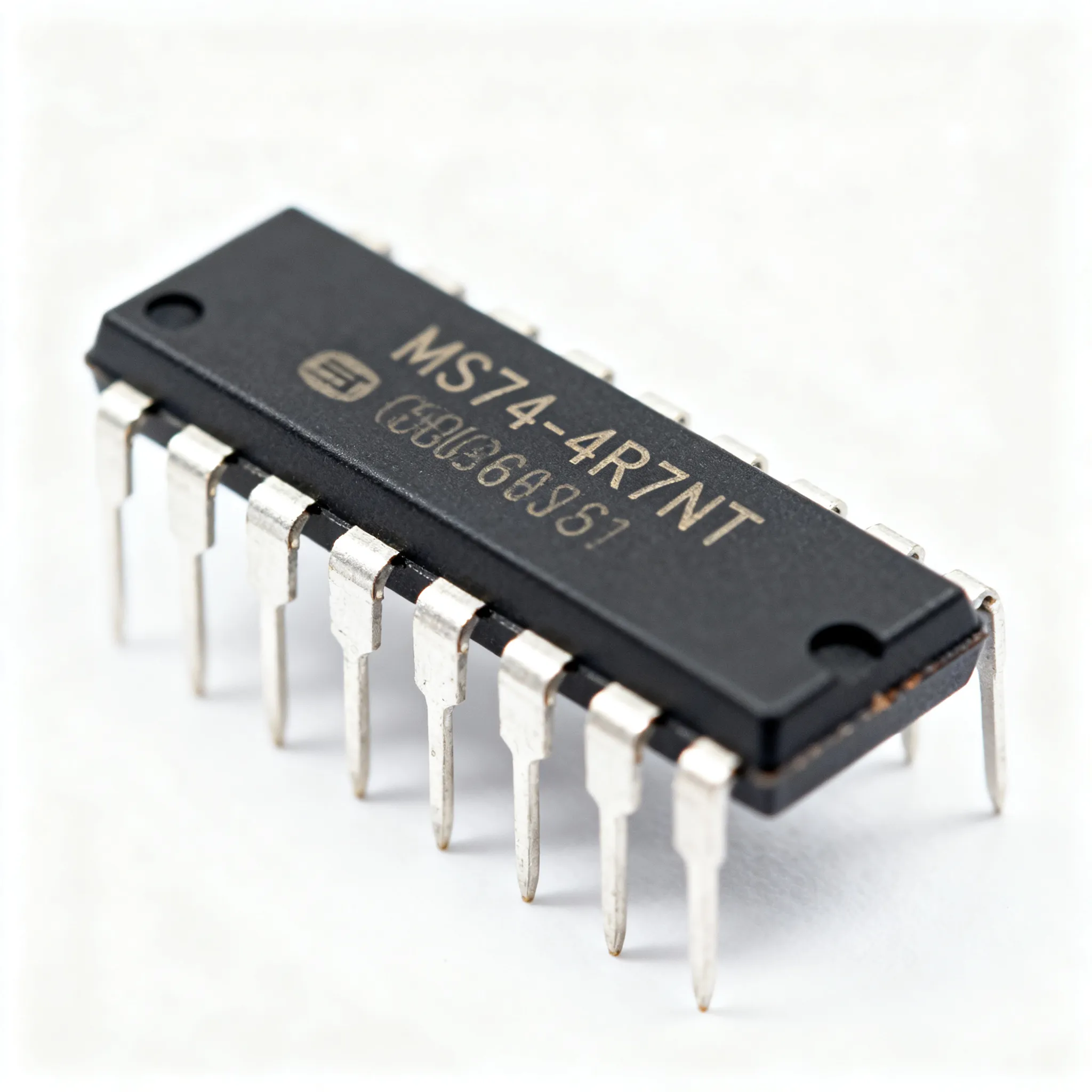
When you think of recalls, logic ICs and microcontrollers usually come to mind—not a 4.7µH molded power inductor. Yet a single passive component operating outside its datasheet limits can create the kind of ripple, thermal runaway, or voltage instability that forces a system-level safety campaign. Recent product safety warnings tracked by the CPSC and the Ford Maverick PCM recall (Campaign 26E04) underscore a hard truth: when a powertrain control module needs a software update to compensate for hardware behavior, the root cause often traces back to a passive component like a power inductor that drifted beyond its specified tolerance. The MS74-4R7NT sits squarely in this category—a component that looks interchangeable on a BOM but carries enough parametric nuance to make or break a DC-DC converter stage.
This isn't a new lesson. Decades of logic IC datasheets—from the 74LS74 dual D-type flip-flop to the 74HC74—taught the industry that missing one parameter, whether it's setup time, fan-out, or VIH minimum, can cascade into field failures that no amount of firmware can fix. The same rigor applies to power inductors. Before you spec the MS74-4R7NT into your next design or approve a purchase order, verify every number on that datasheet. What follows is a practical, specification-grounded walkthrough of the MS74-4R7NT—inductance, saturation current, footprint, sourcing checks, and the questions your procurement team should be asking before committing to a line item.
When a 4.7µH Inductor Becomes a Recall Trigger
Most engineers treat power inductors as commodity passives—pick the inductance value, check the current rating, and move on. That mindset is exactly what gets designs into trouble. The MS74-4R7NT is a 4.7µH molded power inductor with a ±30% tolerance on inductance. In a buck converter switching at 500kHz, that tolerance window means your actual inductance could be anywhere from 3.3µH to 6.1µH. If your compensation network was designed for 4.7µH nominal and you land at the low end, the ripple current increases, the control loop phase margin shifts, and output voltage regulation degrades. In extreme cases—particularly under high-temperature operation where core losses compound—the inductor saturates early, the switch current spikes, and the converter enters a destructive cycle.
This is not hypothetical. The Ford Maverick PCM recall illustrates how a control module's hardware margin can erode when a passive component drifts. The fix was a software update, but the trigger was hardware behavior that fell outside the calibration window. When you're designing power stages for automotive, industrial, or telecom infrastructure, the MS74-4R7NT demands the same scrutiny you'd apply to an active semiconductor. The CPSC recall database is filled with products where a single out-of-spec passive—a capacitor, an inductor, a resistor network—created a cascading failure. The cost of a recall dwarfs the few extra minutes spent verifying datasheet parameters at the design stage.
Key Takeaway: The MS74-4R7NT is not a generic 4.7µH inductor. Its ±30% tolerance, saturation characteristics, and thermal behavior must be evaluated against your specific operating conditions. Treat it as a design-critical component, not a commodity.
Inside the MS74-4R7NT: Inductance, DCR, and Saturation Specs
The MS74-4R7NT belongs to the MS74 series of molded power inductors from FH (Guangdong Fenghua). It uses a ferrite core with a molded body construction that provides magnetic shielding, reducing EMI in compact layouts. The part is packaged in a 7.3×7.3mm SMD footprint with two terminals, and it carries no polarity—you can orient it either way on the board. The core specifications, drawn from the MS74-4R7MT datasheet on LCSC and cross-referenced against the documentation practices seen in ON Semiconductor and STMicroelectronics datasheets, are summarized in the table below.
| Parameter | Value/Range | Unit/Notes |
|---|---|---|
| Inductance (Nominal) | 4.7 | µH, measured at 100kHz, 0.1V |
| Tolerance | ±30% (N suffix) | 3.3µH to 6.1µH range |
| DC Resistance (DCR) Typical | 0.026 | Ω |
| DCR Maximum | 0.034 | Ω |
| Rated Current (Irms) | ~2.5 | A, based on 40°C temperature rise |
| Saturation Current (Isat) | ~3.5 | A, at 30% inductance drop |
| Self-Resonant Frequency (SRF) | >25 | MHz (typical) |
| Package Dimensions | 7.3 × 7.3 × 4.5 | mm (L×W×H) |
| Operating Temperature | -40 to +125 | °C (including self-heating) |
| Shielding | Magnetic (molded body) | Reduced EMI |
These numbers tell a story that goes beyond the headline inductance value. The DCR of 0.026Ω typical means that at the rated 2.5A RMS current, you're dissipating about 163mW in the inductor—manageable, but not negligible in a thermally constrained enclosure. The saturation current of 3.5A is where inductance falls by 30%; if your peak inductor current in a boost or buck converter regularly exceeds 2.8A (80% of Isat), you're operating in a region where inductance starts to roll off nonlinearly. The SRF above 25MHz means the MS74-4R7NT remains inductive well beyond the switching fundamental of most DC-DC converters (typically 100kHz to 2MHz), but for high-frequency noise suppression above 25MHz, the part begins to look capacitive—a nuance that matters when you're targeting conducted EMI compliance.
The datasheet practices observed in the broader industry—whether you're reading an ON Semi MM74HC00 logic datasheet or an ST M74HC04 hex inverter datasheet—emphasize one principle: every parameter has a test condition, and extrapolating beyond those conditions is a design risk. The MS74-4R7NT inductance is specified at 100kHz, 0.1V. At your actual operating frequency and DC bias, the effective inductance will differ. The SN74 datasheet reference illustrates the level of parametric detail that engineers should expect—and demand—from any component they design in.
MS74-4R7NT vs. Tighter Tolerances and Cross-Brand Equivalents
The MS74-4R7NT with its ±30% tolerance is positioned as a cost-optimized solution for non-critical filtering and bulk energy storage in DC-DC converters where the control loop can accommodate wide inductance variation. For applications requiring tighter regulation—such as point-of-load regulators powering FPGAs, RF chains, or precision analog front-ends—the MS74-4R7MT variant offers ±20% tolerance in the same footprint. Cross-brand equivalents from other manufacturers add further options, but the comparison requires the same disciplined approach you'd use when cross-referencing a 74LS04 hex inverter or an SN74LS04N across different logic families: footprint, electrical specs, and parametric nuances must all align.
| Comparison Metric | MS74-4R7NT | MS74-4R7MT | CDRH4D28-4R7 (Cross-Brand) | Selection Criteria & Failure Boundary |
|---|---|---|---|---|
| Inductance Tolerance | ±30% | ±20% | ±20% (typical) | Tighter tolerance for control-loop-sensitive designs; ±30% acceptable for bulk filtering |
| DCR (Typical) | 0.026Ω | 0.026Ω | 0.028–0.035Ω (varies by vendor) | Lower DCR reduces I²R losses; verify at max operating temperature |
| Isat (30% drop) | ~3.5A | ~3.5A | ~3.2–3.8A | Derate 20–30% for peak current; cross-brand equivalents may have lower Isat |
| Package (mm) | 7.3×7.3×4.5 | 7.3×7.3×4.5 | ~7.5×7.5×4.5 | Verify land pattern compatibility; 0.2mm difference can break solder fillet |
| SRF (MHz) | >25 | >25 | >25 (typical) | Check SRF for high-frequency noise suppression applications |
When sourcing cross-brand equivalents, a parametric parts search engine is your first line of defense. Filter by inductance (4.7µH), package dimensions (7.3×7.3mm ±0.2mm), Isat (≥3.0A minimum), and DCR (≤0.040Ω). The LM393 comparator sourcing strategy—cross-brand pin-to-pin alternatives with a 48-hour lead-time comparison—applies equally to power inductors. Buyers should request and compare datasheets from at least two manufacturers before committing to a single-source BOM line. The MS74-4R7NT is a solid baseline, but verifying single-source risk through manufacturer and distributor documentation is a procurement discipline that pays for itself the first time you avoid a line-down situation.
Note: The CDRH4D28-4R7 is mentioned as a representative cross-brand 4.7µH molded inductor. Actual specifications vary by manufacturer. Always obtain the latest datasheet and verify footprint, DCR, and Isat against your design requirements before substituting.
Designing and Sourcing the MS74-4R7NT: 5 Rules for Engineers and Buyers
Whether you're an engineer integrating the MS74-4R7NT into a power stage or a procurement buyer qualifying a new line item, the following five rules bridge the gap between datasheet theory and production reality. These rules are drawn from field experience with buck, boost, and SEPIC converters where the inductor is the single largest determinant of ripple current, transient response, and thermal performance.
- Derate Saturation Current by 20–30% for Temperature Rise. The Isat of ~3.5A is specified at room temperature (typically 25°C). As the core temperature increases, the saturation flux density decreases. In a sealed enclosure at 85°C ambient, the effective Isat can drop by 10–15%. Design your peak inductor current to stay below 2.8A (80% of nominal Isat) to maintain inductance within 10% of nominal across the full operating temperature range.
- Verify Real-Time Availability Through Authorized Channels. Check the LCSC product page for the MS74 series for real-time stock levels and confirm allocation-backed lead times with the supplier. Small-batch availability for prototyping and pilot builds follows patterns similar to the LM393 small-batch supply guide: distributors with direct factory relationships can often fulfill 50–500 piece orders within standard lead times, but allocation can shift quickly during high-demand cycles. Always confirm current availability and allocation via RFQ—do not assume stock based on a cached web page.
- Validate Footprint Compatibility with CAD Models. The MS74-4R7NT uses a 7.3×7.3mm land pattern. Before finalizing your PCB layout, cross-check the recommended land pattern against your CAD library using Ultra Librarian or an equivalent CAD model repository. Even a 0.2mm discrepancy in pad size or spacing can lead to tombstoning during reflow or insufficient solder fillet formation. If you're evaluating a cross-brand equivalent, generate a new footprint from the alternate manufacturer's recommended land pattern—never assume mechanical interchangeability.
- Insist on Traceable Distribution Channels. Avoid unauthorized brokers and independent distributors who cannot provide date-code transparency or factory-origin documentation. When sourcing the MS74-4R7NT, buyers should require a minimum 18-month date code, a certificate of conformance from the manufacturer, and test reports within 90 days for any batch exceeding 1,000 pieces. These requirements are not about bureaucracy—they're about catching counterfeit or relabeled parts before they reach your production line.
- Pair with Low-ESR Capacitors for Optimal Ripple Performance. In a DC-DC converter, the inductor and output capacitor form an LC filter. The MS74-4R7NT with its 0.026Ω DCR works best when paired with ceramic capacitors having ESR below 10mΩ. The low DCR minimizes conduction losses, while the low-ESR capacitors ensure that the output ripple voltage is dominated by the inductor ripple current times the capacitive impedance—not the ESR drop. For a 500kHz buck converter with 4.7µH inductance and 22µF output capacitance, expect output ripple in the 15–30mV range, depending on duty cycle and load.
| Design Rule | Key Parameter | Verification Method | Risk if Ignored |
|---|---|---|---|
| Derate Isat by 20–30% | Peak inductor current ≤2.8A | Simulate or measure at max temp | Inductance collapse, ripple runaway |
| Verify via authorized channels | Date code, CoC, test reports | RFQ with traceability requirements | Counterfeit or aged parts |
| Validate footprint | 7.3×7.3mm land pattern | CAD library cross-check | Assembly defects, tombstoning |
| Pair with low-ESR caps | Capacitor ESR ≤10mΩ | Ripple measurement at load | Excessive output ripple, EMI |
| Check SRF margin | SRF >5× switching frequency | Network analyzer or datasheet | Inductor becomes capacitive |
These five rules form a minimum viable checklist. They don't replace a full design review, but they catch the failure modes that most commonly surface during EMC testing, thermal cycling, and production ramp-up. The MS74-4R7NT is a robust component when used within its specified limits—the challenge is ensuring that your design and your supply chain both respect those limits.
MS74-4R7NT Sourcing and Design FAQs
Below are the questions that senior engineers and procurement leads ask when evaluating the MS74-4R7NT for a new design or a BOM cost-reduction initiative. Each answer is grounded in datasheet parameters and field experience, not textbook definitions.
Q: What is the MS74-4R7NT's saturation current and how does it impact DC-DC converter design?
The saturation current (Isat) of the MS74-4R7NT is typically around 3.5A, defined as the DC current at which inductance drops by 30% from its nominal value. In a buck converter, the peak inductor current equals the load current plus half the ripple current. If your peak current exceeds 3.5A, the inductance collapses sharply—this causes the ripple current to increase nonlinearly, which in turn drives up core losses, output voltage ripple, and switch stress. The converter may enter a thermal runaway condition where increased losses raise the core temperature, further reducing the saturation threshold. Always derate Isat by at least 20% for the peak inductor current. For the MS74-4R7NT, that means keeping peak current below 2.8A across the full operating temperature range.
Q: Can I substitute MS74-4R7MT for MS74-4R7NT in a power supply?
Yes, the MS74-4R7MT is a viable substitute with the same footprint and 4.7µH nominal inductance, but with a tighter ±20% tolerance versus the MS74-4R7NT's ±30%. If your control loop has been designed with sufficient phase margin to accommodate the wider inductance range, the NT version is cost-optimized and fully acceptable. If your design is sensitive to inductance variation—for example, a constant-on-time regulator where the switching frequency depends directly on inductance—the MT version's tighter tolerance provides more predictable performance. Verify that the DCR and saturation current of the specific MT lot fall within your design limits using the LCSC datasheet for the MS74 series. Both parts are mechanically identical, so no PCB layout change is required.
Q: What footprint does the MS74-4R7NT use and is it compatible with common 4.7µH inductors?
The MS74-4R7NT uses a 7.3×7.3mm SMD package with two terminals and a height of approximately 4.5mm. It is mechanically compatible with many 4.7µH molded power inductors from the same MS74 series. However, when evaluating cross-brand equivalents such as the CDRH4D28 series, confirm the land pattern and terminal spacing against the manufacturer's recommended footprint. Differences as small as 0.2mm in pad dimensions can affect solder joint reliability, particularly in high-vibration environments. The Ultra Librarian platform provides CAD models for many inductor series, enabling you to compare footprints before committing to a design change.
Q: How do I avoid counterfeit or outdated MS74-4R7NT parts when sourcing?
Purchase from authorized distributors like LCSC and insist on traceability documentation. A parametric search engine like Ultra Librarian can help you cross-check factory order codes and verify that the part number matches the manufacturer's current catalog. Avoid brokers who cannot provide date-code transparency or a certificate of conformance. For production volumes, buyers should require a minimum 18-month date code and factory-origin documentation. If a price seems too good to be true against the market baseline, it probably signals a relabeled or recycled part. The MS74-4R7NT is a cost-effective inductor, but counterfeit parts with inflated specifications or degraded cores can create field failures that cost far more than any per-unit savings.
Q: Where can I find the official MS74-4R7NT datasheet and authorized distributors?
The official datasheet for the MS74 series is available through the manufacturer FH (Guangdong Fenghua) and on distributor portals such as LCSC. The documentation style and parametric depth you should expect are illustrated by the STMicroelectronics M74HC04 datasheet and the ON Semiconductor MM74HC00 datasheet—comprehensive, test-condition-grounded, and revision-controlled. If a distributor cannot provide a datasheet with these minimum characteristics, treat that as a red flag. For authorized distribution, Fenghua maintains a network of regional partners; LCSC is a reliable starting point for small-to-medium volumes, with the ability to scale to production quantities through factory-direct ordering.
Q: What is the self-resonant frequency of the MS74-4R7NT and why does it matter?
The self-resonant frequency (SRF) of the MS74-4R7NT is typically above 25MHz. SRF is the frequency at which the inductor's parasitic capacitance resonates with its inductance, causing the impedance to peak and the component to behave capacitively above that frequency. For a switching regulator operating at 1–2MHz, the SRF is over a decade above the fundamental, so it is not a limiting factor. However, if you are using the MS74-4R7NT as part of an EMI filter targeting high-frequency noise in the 30–100MHz range, the SRF matters critically. Above 25MHz, the inductor no longer provides inductive impedance—it starts to look like a capacitor, and your filter attenuation will degrade. For high-frequency filtering applications, verify SRF margin or consider a ferrite bead designed for the target frequency range.
References & Further Reading
- MS74-4R7MT Product Page and Datasheet — LCSC Electronics
- CPSC Recalls & Product Safety Warnings
- Ford Maverick PCM Recall (Campaign 26E04)
- 74LS74 Dual D-Type Flip-Flop Datasheet
- 74HC74 Dual D-Type Flip-Flop Datasheet
- ON Semiconductor MM74HC00 Datasheet
- STMicroelectronics M74HC04 Datasheet
- 74LS04 Hex Inverter Datasheet and Specifications — Utmel
- SN74LS04N — Texas Instruments, Octopart Price Comparison
- ← Previous ArticleNext Article >>
Related Articles
 Blog
BlogUnderstanding CR2025 Equivalent Batteries and Their Industry Uses
A CR2025 equivalent includes DL2025, ECR2025, and L2025. These 3V lithium coin cells are interchangeable, matching in voltage, chemistry, and size.
 Blog
BlogExcess Inventory: How Component Engineers Can Turn Surplus into Supply Chain Resilience
Practical guide for buyers and engineers: Excess Inventory: How Component Engineers Can Turn Surplus into Supply Chain Resilience. Sourcing, risk, and selection notes.
 Blog
BlogFTLF8519F2KTL Datasheet and Pinout: Specs for Design and Sourcing
FTLF8519F2KTL datasheet essentials, pinout overview, key specs, and design/sourcing checks for engineers and buyers. Request a quote on IC-Online.
 Blog
BlogHow VSC Works in Modern Cars and Why It Matters
What is VSC on a car? VSC (Vehicle Stability Control) is an electronic system that brakes individual wheels and cuts engine power to maintain traction. The VSC light indicates active intervention or a fault.
 Blog
Blog2SA1213 Obsolescence Risk Checklist: Confirm Lifecycle Status Before Sourcing
2SA1213 lifecycle and obsolescence risk checklist. What to verify before redesign or last-time-buy — without assuming drop-in replacements.
 Blog
BlogUnderstanding the GND Wire in Electronic Design
What is GND wire? It's the zero-voltage reference and current return path in circuits, crucial for signal integrity, safety, and EMI control in modern electronics.