Powering a 3.3V MCU from 12V: A TPS563209DDCR Design Walkthrough
Expert guide on Powering a 3.3V MCU from 12V: A TPS563209DDCR Design Walkthrough. Technical specs, applications, sourcing tips for engineers and buyers.
Why 12V-to-3.3V Regulation Keeps Failing in the Field
It happens in a flash: the instrument cluster goes blank, the dashboard blacks out, and a driver loses speedometer and warning indicators. The root cause is often a mundane power-supply rail that couldn’t handle the jump from a nominal 12 V battery bus to a clean 3.3 V microcontroller supply. Two recent field events put this failure mode into sharp focus.
In late 2025, Ford issued NHTSA recall 25V788 for 2025–2026 Bronco Sport models after reports of instrument cluster panel display failures. Forum discussions pointed to batches of clusters already built and in storage, but the recall investigation revealed that the 3.3 V rail derived from the vehicle’s 12 V system was susceptible to brownouts and noise-induced resets. Separately, Hyundai’s Integrated Charging Control Unit (ICCU) recall on Ioniq 5 and EV6 models highlighted a different 12 V-to-low-voltage failure: overvoltage at the start and end of the 12 V battery charging cycle, combined with thermal stress, damaged downstream electronics. Both cases underscore a central truth: a 12 V nominal rail in an automotive or industrial environment is anything but quiet, and the DC-DC converter that steps it down to 3.3 V must be robust, fast, and thermally efficient.
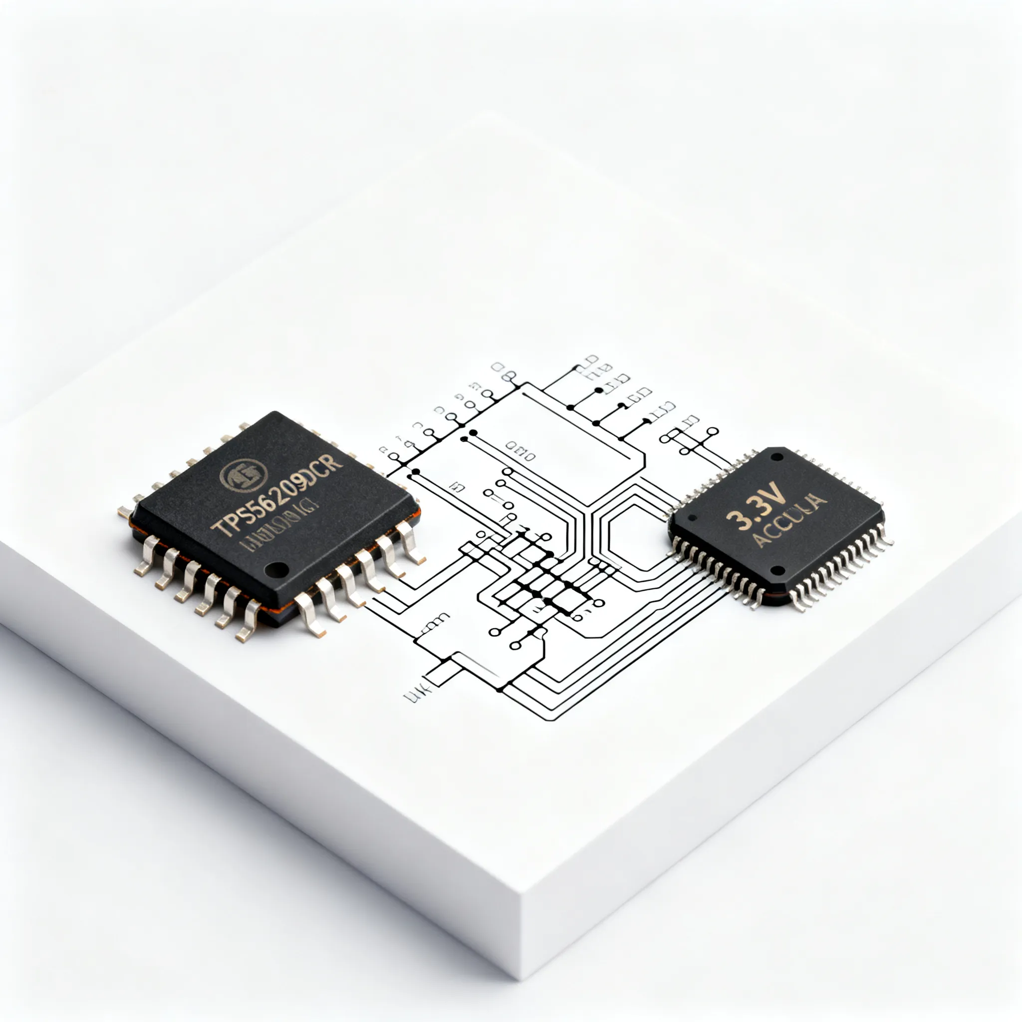
Engineers who have faced intermittent MCU resets, ADC drift, or flash corruption in the field know the pain. A linear regulator is often the first thought, but the power dissipation quickly becomes untenable. The solution is a synchronous buck converter that can handle input transients, deliver a tight 3.3 V rail, and fit in a tiny footprint. That’s where the TPS563209DDCR from Texas Instruments enters the picture. This 17 V, 3 A synchronous step-down converter in a 6-pin SOT-23 package (DDC) is purpose-built for exactly this job, and its datasheet (overview) outlines a design that can avoid the field failures that plague dashboard electronics and ECU power rails.
Inside the TPS563209: Key Specs and Synchronous Buck Operation
The TPS563209DDCR is a fixed-frequency, peak-current-mode synchronous buck regulator. Its power stage integrates both high-side and low-side MOSFETs, eliminating the need for an external Schottky diode and reducing component count and PCB area. The converter switches at a nominal 580 kHz, a sweet spot that balances efficiency, inductor size, and transient response for a 12 V-to-3.3 V application.
With an input voltage range of 4.5 V to 17 V, the device comfortably operates from a 12 V battery bus that can sag to 6 V during cold crank or spike to 16 V during charging. The 3 A continuous output current capability is more than enough for a typical 3.3 V MCU, its peripherals, and even a small display or wireless module. The integrated synchronous rectification keeps efficiency above 90% across most of the load range, which is critical for thermal management and battery life.
Let’s lay out the essential parameters that matter when you’re designing a 12 V-to-3.3 V rail:
| Parameter | Value / Range | Notes |
|---|---|---|
| Input voltage, VIN | 4.5 V to 17 V | Absolute maximum 19 V; 12 V nominal with transient headroom |
| Output voltage, VOUT | Adjustable down to 0.768 V | Set via resistor divider; 3.3 V is a standard target |
| Continuous output current | 3 A | Thermally limited; derate above 85°C ambient |
| Switching frequency | 580 kHz (typical) | Fixed frequency; forces predictable EMI spectrum |
| Peak efficiency | Up to 95% | 12 V in, 3.3 V out, 1 A load; synchronous rectification |
| Quiescent current (non-switching) | 110 µA (typical) | Eco-mode version; rises in forced PWM mode |
| Package | SOT-23-THN (6-pin, DDC) | 2.9 mm × 1.6 mm; power pad for thermal dissipation |
| Operating junction temperature | -40°C to +125°C | Industrial grade, suits under-hood and outdoor enclosures |
| Protection features | Cycle-by-cycle current limit, thermal shutdown, UVLO | Hiccup mode on overcurrent |
The synchronous rectification is the secret sauce that makes this tiny SOT-23 package deliver 3 A without a heatsink. At 12 V input and 3.3 V output, the duty cycle is roughly 27.5%. The high-side MOSFET is on for only a fraction of the period, while the low-side MOSFET conducts the inductor current during the off-time. The integrated low-side FET has an RDS(on) typically below 60 mΩ, so conduction losses stay low. Combined with the 580 kHz switching, you can use a compact 4.7 µH inductor and still keep peak-to-peak ripple current around 30% of the full load, a good balance for loop stability and output ripple.
The fixed-frequency PWM architecture simplifies the input filter design and avoids the variable-frequency EMI spectrum that can plague hysteretic converters. Because the switching frequency is consistent, you can easily predict and mitigate noise coupling into sensitive analog MCU inputs. The internal compensation network is optimized for the 580 kHz frequency, so you only need to select the output LC filter and feedback resistors. The TI product page and the full datasheet provide detailed internal block diagrams and application curves that confirm the loop bandwidth and phase margin for a 3.3 V output.
TPS563201 vs. TPS563209: Choosing the Right SOT-23 Regulator
Texas Instruments offers two closely related 3 A synchronous buck converters in the same 6-pin SOT-23 package: the TPS563209DDCR and the TPS563201DDCR. On the surface they look identical—same pinout, same voltage and current ratings—but the difference in operating mode can make or break your MCU power design. The choice boils down to how the converter behaves at light loads and whether you need the higher temperature range.
The TPS563201DDCR operates in forced PWM (FPWM) mode. It keeps the switching frequency constant at all loads, which means the output ripple is predictable and low, but the quiescent current and switching losses at light load remain high. The TPS563209DDCR uses Eco-mode (pulse-skipping) at light loads. Below a certain current threshold, it turns off the low-side MOSFET and enters a discontinuous conduction mode, reducing switching losses and drawing only 110 µA of quiescent current. This is a boon for battery-powered MCU systems that spend most of their time in sleep, waking periodically to take a sensor reading and transmit data. In Eco-mode, the efficiency at 10 mA can be above 80%, whereas forced PWM might drop to 60% or less.
The second critical difference is the operating temperature range. The TPS563201DDCR is rated for a junction temperature of -40°C to +125°C, while the TPS563209DDCR spans -40°C to +85°C. For an under-hood automotive ECU or an outdoor industrial controller that sees extreme heat, the 125°C rating of the TPS563201 may be mandatory. For a dashboard instrument cluster or a consumer appliance that sits in a controlled environment, the 85°C rating of the TPS563209 is usually sufficient and often comes with a slight cost advantage and better light-load efficiency.
Here’s a side-by-side comparison to help you decide:
| Comparison Metric | TPS563209 (Eco-mode) | TPS563201 (Forced PWM) | Selection Criteria & Failure Boundary |
|---|---|---|---|
| Light-load operation | Eco-mode (pulse-skipping); variable frequency | Forced PWM; constant 580 kHz | Eco-mode saves power in sleep/wake MCU cycles; forced PWM is necessary if the rail must be kept quiet for sensitive analog circuits at all loads |
| Quiescent current (non-switching) | 110 µA typical | ~1.5 mA typical | Battery life impact: Eco-mode extends standby time by an order of magnitude |
| Output ripple at light load | Higher, variable frequency bursts | Low, constant frequency | If the MCU ADC requires <10 mV ripple, forced PWM may be safer; otherwise, a post-filter can clean up Eco-mode ripple |
| Junction temperature range | -40°C to +85°C | -40°C to +125°C | Automotive and harsh industrial environments need 125°C; commercial/consumer can use 85°C |
| Typical efficiency at 12 V in, 3.3 V out, 10 mA | ~82% | ~60% | For always-on sensors, the TPS563209 saves significant battery energy |
Both parts are available from distributors like Mouser and the TI store. The TPS563201DDCR listing on Mouser and the TI part details page show real-time inventory. For a 12 V-to-3.3 V MCU supply that sleeps most of the time, the TPS563209DDCR is the superior choice, provided you can manage the slightly higher light-load ripple and the 85°C limit. If your MCU must wake up and sample a precision ADC within microseconds, the forced PWM variant might be worth the extra quiescent current to keep the rail clean at all times.
From Schematic to Stable 3.3V: Layout and BOM Tips
Getting a 3.3 V rail from 12 V with the TPS563209DDCR is not just about the IC—it’s the entire power stage layout that determines whether your MCU sees a clean supply or a noisy, glitch-prone voltage. Even a board that works on the bench can fail in the field if the layout ignores the high di/dt loops and the thermal path.
Start with the output inductor. For a 3.3 V output at 580 kHz, a 4.7 µH inductor gives a peak-to-peak ripple current of about 0.9 A at 3 A load. Choose a shielded inductor with low DCR (less than 30 mΩ) and a saturation current rating of at least 4 A. The inductor sits between the SW pin and the output capacitor. The SW node is the most critical copper area: it swings from ground to VIN at 580 kHz, creating an electric field radiator. Keep this copper area as small as possible—just enough to connect the SW pin, the inductor pad, and the bootstrap capacitor. Speaking of the bootstrap capacitor, a 0.1 µF ceramic capacitor must be placed directly between the BOOT and SW pins, with minimal trace length. The internal high-side driver uses this capacitor to generate the gate drive voltage, and any impedance here can cause erratic switching.
The input capacitor (typically 10 µF ceramic plus a bulk 22 µF electrolytic) must be placed as close to the VIN and GND pins as possible. The high-frequency current loop formed by the input capacitor, the high-side MOSFET, the inductor, and the output capacitor sees very fast di/dt; a tight loop keeps EMI low and reduces voltage spikes on the input. Use a solid ground plane on the layer directly beneath the IC. The power pad of the SOT-23-6 package must be soldered to a copper area that connects to the ground plane with multiple thermal vias. This pad is the primary heat path—without a good connection, the junction temperature can rise quickly at 3 A load. TI recommends at least four 0.3 mm vias in the pad area.
Output capacitor selection is crucial for transient response. The TPS563209DDCR can respond to a load step within a few switching cycles, but the output capacitor must supply the current during the initial dip. Use a low-ESR ceramic capacitor of 22 µF or 2×10 µF placed physically close to the MCU supply pins. The voltage droop during a 0-to-1 A load step is typically less than 50 mV with a 22 µF output capacitor, thanks to the 580 kHz loop bandwidth.
Here’s a recommended BOM for a 12 V-to-3.3 V, 3 A design:
| Component | Recommended Part / Value | Notes |
|---|---|---|
| U1 – Buck converter | TPS563209DDCR | 6-pin SOT-23, Eco-mode, 85°C |
| L1 – Inductor | 4.7 µH, 4 A, DCR < 30 mΩ | Shielded; e.g., Coilcraft XAL40xx or Würth 74437368047 |
| CIN – Input ceramic | 10 µF, 25 V, X7R, 1206 | Place within 5 mm of VIN/GND pins |
| CIN bulk | 22 µF, 25 V, electrolytic or polymer | Damps input ringing; optional but recommended |
| COUT – Output ceramic | 22 µF, 10 V, X7R, 0805 or 1206 | Low ESR; use two 10 µF in parallel for better transient response |
| CBOOT – Bootstrap | 0.1 µF, 16 V, X7R, 0402 | Place directly between BOOT and SW pins |
| R1, R2 – Feedback divider | R1 = 10 kΩ, R2 = 31.6 kΩ (for 3.3 V) | VOUT = 0.768 V × (1 + R1/R2); use 1% tolerance |
| CFF – Feedforward | 22 pF, 50 V, C0G (optional) | Parallel with R1 to improve load transient; can be omitted |
When sourcing, you can find the TPS563209DDCR at Mouser and directly from the TI store. Both channels typically hold stock in the thousands, and in mid-2025 lead times for new orders are around 6–8 weeks. Always check current distributor inventory before committing to a production schedule.
Tip: If you see excessive ringing on the SW node—more than 30% overshoot—add a small RC snubber (e.g., 2 Ω and 470 pF) from SW to ground. This dampens the parasitic LC resonance and reduces EMI. However, a tight layout often eliminates the need for a snubber.
A solid ground plane, continuous and unbroken under the entire power stage, is your best friend. It provides a low-impedance return path for the switched currents and shields the MCU from magnetic fields. Avoid routing sensitive analog traces parallel to the SW node or inductor. If you follow these layout rules, the 3.3 V rail will be clean, stable, and immune to the kinds of field failures that grounded the Bronco Sport clusters.
TPS563209DDCR Design Questions Engineers Ask
Over years of power-supply reviews, I’ve seen the same questions pop up when a senior engineer evaluates a buck converter for a microcontroller rail. Here are the most critical ones, answered with the TPS563209DDCR in mind.
Q: What's the minimum input voltage for a stable 3.3V output at full 3A load?
The TPS563209 requires at least 4.5 V input to start up and operate. To maintain 3.3 V regulation, the dropout voltage is less than 300 mV at 3 A, so a 12 V rail provides ample headroom. The device cannot operate below 4.5 V; if your system sees a 12 V battery sag to 4 V during a cold crank, you must either use a boost pre-regulator or accept that the 3.3 V rail will collapse. In practice, the 4.5 V minimum is rarely a problem for a healthy 12 V bus.
Q: Can I use the TPS563209 in an automotive application that must survive load-dump transients?
The absolute maximum input voltage is 17 V (19 V transient), so a 12 V automotive system cannot connect directly to the battery without protection. A central load-dump pulse can reach 40 V for hundreds of milliseconds. You must place a transient voltage suppressor (TVS) diode, such as a 15 V bidirectional TVS, at the input, along with a series resistor or an LC filter to limit the current. TI reference designs often include a SMAJ15A or similar TVS; the clamping voltage keeps the input below 17 V. Always verify the TVS clamping voltage with the surge current profile.
Q: How does the TPS563209 handle the load transient when an MCU wakes from sleep and draws a fast current spike?
With synchronous rectification and a 580 kHz switching frequency, the converter can respond within a few switching cycles. The internal error amplifier and compensation network are designed for a crossover frequency around 50 kHz, so the feedback loop recovers in tens of microseconds. The output capacitor is the first line of defense. Use a low-ESR ceramic capacitor of 22 µF (or 2×10 µF) placed close to the MCU. During a 0 mA to 500 mA step, the voltage droop is typically less than 30 mV and recovers within 50 µs, well within the MCU’s brown-out tolerance.
Q: What's the typical lead time for the TPS563209DDCR in 2025?
As of mid-2025, both Mouser and the TI store show stock availability with thousands of units on the shelf. Lead times for new, non-stocked orders are typically 6–8 weeks. The DDCR variant (SOT-23-6, tape and reel) is the most popular, so distributors maintain a healthy buffer. Always check the latest inventory before finalizing your BOM; the Mouser product page shows real-time stock levels.
Q: Why choose the TPS563209 over a simple 3.3V LDO from a 12V rail?
An LDO would dissipate (12 V – 3.3 V) × IOUT as heat. At just 500 mA, that’s 4.35 W, requiring a heatsink and forced airflow. At 3 A, the LDO would burn 26 W—impossible without a massive thermal solution. The TPS563209DDCR synchronous buck achieves over 90% efficiency, so at 3 A output, the power loss is less than 1 W. The SOT-23 package handles that with a modest copper area, keeping the entire solution compact and cool. For any load above 100 mA, the buck converter is the only practical choice from a 12 V bus.
Q: Does the TPS563209 require a bootstrap capacitor and what are the layout implications?
Yes, the internal high-side MOSFET driver needs a bootstrap capacitor between the BOOT and SW pins. A 0.1 µF ceramic capacitor is typical. Position this capacitor as close as physically possible to the pins—short, wide traces are essential to minimize inductance. The SW node is a high-frequency switching node, so keep its copper area small to limit radiated EMI. The bootstrap capacitor is recharged each cycle when the low-side FET turns on, so a solid ground connection to the SW node is critical for reliable operation.
Selecting the right converter for your 12 V-to-3.3 V MCU rail is more than a datasheet exercise. It’s about understanding the real-world stress that your power supply will face—from load-dump pulses to sub-millisecond load transients—and choosing a device and layout that can handle them without drama. The TPS563209DDCR provides a battle-tested, compact, and efficient foundation, and with the layout tips and component choices outlined here, your design can avoid the field failures that have plagued recent automotive electronics.
References & Further Reading
- TPS563209DDCR Datasheet – All About Circuits
- TPS563209 Product Page – Texas Instruments
- TPS563209 Datasheet – Alldatasheet
- TPS563209DDCR at Mouser
- TPS563209DDCR at TI Store
- TPS563201DDCR at Mouser
- TPS563201DDCR Part Details – TI
- Ford Bronco Sport Instrument Cluster Recall Discussion
- Hyundai ICCU Failure Analysis – InsideEVs
For sourcing complete BOMs and managing mixed-MOQ requirements, visit IC-Online, where you can find the TPS563209DDCR and supporting passives from a single, flexible supply chain.