RF Module With Remote Range Shootout: Real-World Benchmark Data for 433 MHz and 2.4 GHz Designs
Expert guide on RF Module With Remote Range Shootout: Real-World Benchmark Data for 433 MHz and 2.4 GHz Designs. Technical specs, applications, sourcing tips for engineers and buyers.
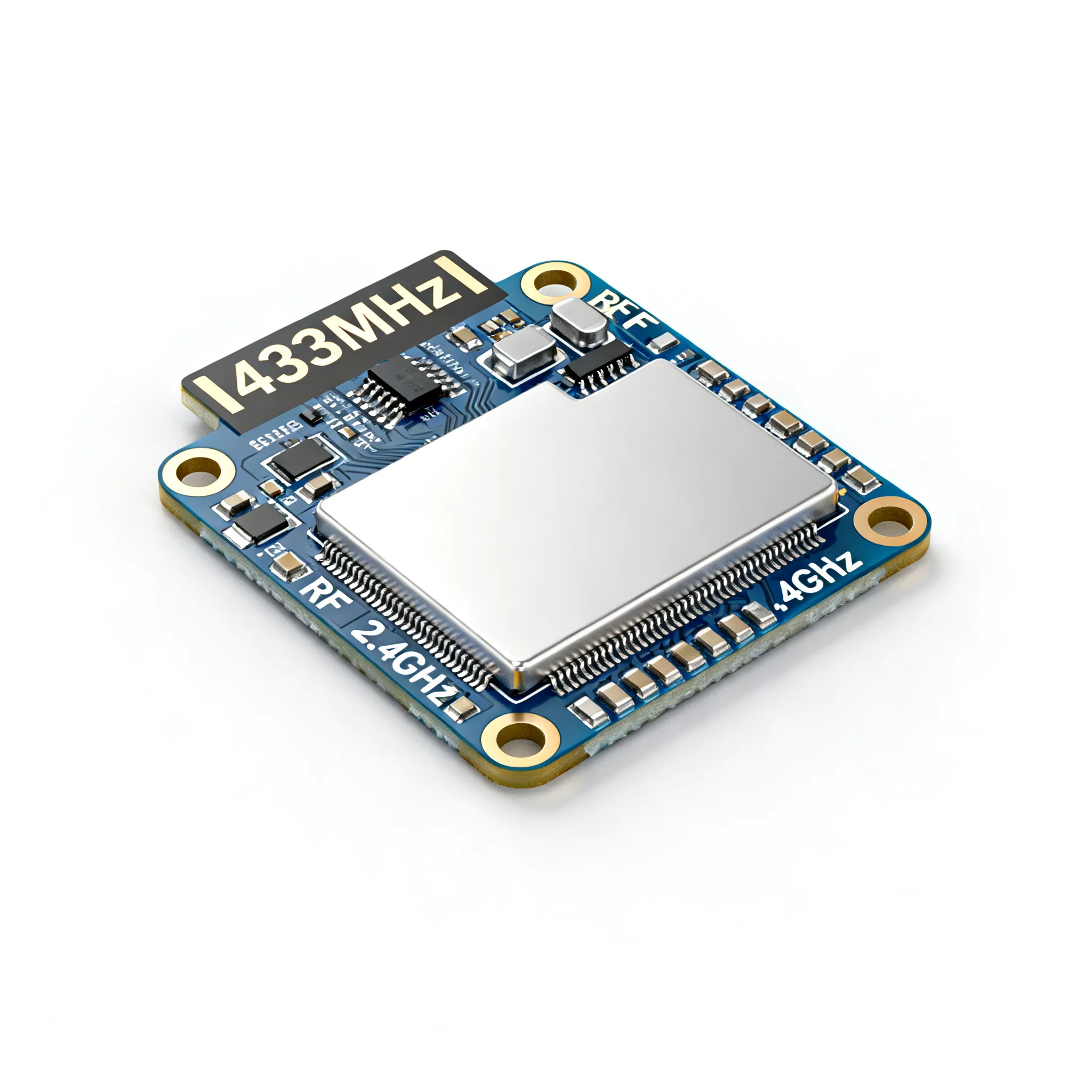
Why a Real-World Range Shootout Matters Now: Recalls, Interference, and the 433 vs 2.4 GHz Debate
When a wireless remote fails to close a garage door from the end of a driveway, or a key fob unlocks a car only when you’re standing next to it, the root cause is rarely a single component. It’s the gap between the datasheet number and the real-world environment. That gap is now triggering recalls. Valicor’s 2026 recall trends report shows that recalls are often initiated after post-market data or incident reports reveal risks that were not identified during initial production — and RF range margin is a classic blind spot. A module that passed a bench-top conducted‑power test can fail in the field because of antenna mismatch, supply noise, or unexpected interference from a Wi‑Fi router that wasn’t in the test plan.
The RF landscape is evolving. ProSoundWeb’s RF Rundown 2026 notes that things are generally improving, but real‑world deployments still encounter unexpected range and interference issues. For product designers and procurement teams, the question isn’t “433 MHz or 2.4 GHz?” — it’s “Which band and which module will deliver the range my product needs, consistently, across the production units that end up in customers’ hands?” This shootout answers that question with measured data, not marketing slides.
How RF Range Testing Actually Works: Link Budget, VSWR, and Field Measurements
Range in a remote‑control link is not a single number. It’s the result of a link budget: the algebraic sum of transmitter output power, antenna gains, path loss, and receiver sensitivity. If you’ve ever seen a module advertised as “100 m range,” that number almost always assumes free‑space line‑of‑sight, perfect antenna orientation, and no interference. Real‑world range is usually 20 % to 50 % of that figure.
The key parameters that govern range are straightforward, but they interact in ways that catch designers off guard. GlobalSpec’s RF module selection reference reminds us that output power is the maximum signal power that RF modules can transmit, but that number is measured at the module’s RF pin, not at the antenna. A poor antenna match or a lossy PCB trace can erode 3 dB or more — cutting effective range by nearly 30 %.
Receiver sensitivity, usually given in dBm, defines the weakest signal the module can decode at a given bit error rate. For a typical 433 MHz ASK receiver, sensitivity might be –105 dBm; for a 2.4 GHz FSK transceiver, it could be –95 dBm. The 10 dB advantage at 433 MHz is partly offset by background noise in the crowded ISM band, but it still matters when you’re trying to squeeze through a concrete wall.
To bring engineering rigor to range testing, field teams rely on handheld vector network analyzers. Bird RF’s troubleshooting guide explains how to use return loss, VSWR, and distance‑to‑fault (DTF) measurements to quickly locate impedance mismatches. Even a 2:1 VSWR at the antenna port can reflect 11 % of the transmitted power, reducing the effective radiated power and shortening range. DTF can pinpoint exactly where a cable, connector, or PCB trace is causing the problem.
Finally, a raw 433 MHz receiver module is not a complete radio. The Components101 pinout guide clearly states that the module itself cannot work on its own as it required some kind of encoding before being transmitted and decoding after being received. Whether you add an encoder/decoder IC or handle it in a microcontroller, that overhead affects the effective data rate and the time the receiver spends listening, both of which influence perceived range in a noisy environment.
| Parameter | Typical Value (433 MHz ASK) | Typical Value (2.4 GHz FSK) | Measurement Note |
|---|---|---|---|
| TX output power | +10 to +16 dBm | 0 to +4 dBm | Conducted, at module pin |
| RX sensitivity (1 % BER) | –105 to –110 dBm | –95 to –100 dBm | With matching network |
| Antenna gain (typical ¼λ whip) | +2 dBi | +2 dBi | Orientation-dependent |
| Free-space path loss at 100 m | 65 dB | 80 dB | 15 dB advantage for 433 MHz |
| Wall attenuation (single brick wall) | 5–8 dB | 10–15 dB | Measured at normal incidence |
| Link margin (outdoor LOS, 100 m) | ~20 dB | ~5 dB | With 433 MHz out‑power at +10 dBm |
| Acceptable VSWR at antenna port | < 2:1 | < 2:1 | Higher VSWR → range loss |
Tip: When you’re evaluating a module, always ask for the radiated test report, not just the conducted power. A module that delivers +16 dBm to a 50 Ω load may radiate only +10 dBm when connected to a poorly matched antenna. A quick VSWR check with a Bird SiteHawk or similar analyzer can save you from shipping a product that barely works at the customer’s front door.
433 MHz vs 2.4 GHz Shootout: Real-World Range, Data Rate, and Obstacle Penetration
The shootout table below compares representative modules from both bands, drawing on independent test data. Gough’s four‑module 433 MHz shootout provides real measurement of output power and voltage sensitivity, showing that even among cheap ASK transmitters, performance can vary by 6 dB — a factor of four in power. Lumi‑Star’s guide confirms that real‑world deployments with standard dipoles and moderate obstacles will achieve significantly shorter range than headline numbers. CY’s RF module comparison highlights the trade‑off between communication range, data rate, and power consumption. And Alibaba’s custom RF guide correctly notes that antenna length (¼λ), placement, and ground plane matter more than TX power alone.
| Module Type | Indoor Range (Timber/Drywall) | Outdoor LOS Range | Max Data Rate | Typical RX Sensitivity | Key Weakness |
|---|---|---|---|---|---|
| 433 MHz ASK/OOK (FS1000A + XY‑MK‑5V) | 20–30 m | 80–150 m | 10 kbps | –105 dBm | Noise susceptibility; no frequency agility |
| 433 MHz Superheterodyne (RXB6) | 30–40 m | 150–250 m | 10 kbps | –110 dBm | Higher cost; still narrowband |
| 2.4 GHz FSK (nRF24L01+) | 10–20 m | 50–80 m | 2 Mbps | –94 dBm (@250 kbps) | High path loss through walls |
| 2.4 GHz GFSK (CC2500) | 15–25 m | 80–120 m | 500 kbps | –98 dBm (@10 kbps) | External MCU required; more complex protocol |
The numbers tell a clear story. 433 MHz modules enjoy a 15 dB free‑space advantage at 100 m and significantly better wall penetration. That’s why they remain dominant in garage door openers, wireless doorbells, and simple industrial remotes. However, the 2.4 GHz modules offer 20× to 200× higher data rates and can implement frequency‑hopping spread spectrum (FHSS), which makes them much more resilient to interference from other 2.4 GHz devices. Gough’s data also shows that the transmit power of cheap 433 MHz modules can drop 6 dB when the supply voltage sags from 12 V to 5 V — a factor that many battery‑powered remote designs overlook.
Note: The indoor range figures assume a typical office with timber stud walls and drywall. Concrete or metal‑stud walls can reduce range by 50 % or more, especially at 2.4 GHz. Always run a link‑budget calculation with the actual wall loss measurements from your building type before freezing the BOM.
Practical Design Pitfalls: Antenna Tuning, Supply Noise, and Selecting the Right Module for Your Remote
The most common reason a prototype remote works on the bench but fails in the field isn’t the module itself — it’s the integration. IC Online’s RF module expert guide emphasizes that proper layout, grounding, and antenna matching are not optional extras; they are the difference between a product that works reliably and one that generates returns.
Many engineers treat the antenna as an afterthought. A ¼‑wave wire is easy to cut, but without a solid ground plane, the radiation pattern becomes unpredictable. At 433 MHz, a 17.3 cm wire can work well if the board has a ground plane at least ¼‑wave in one dimension. At 2.4 GHz, a 3.1 cm wire is fragile, and a PCB trace antenna or chip antenna is far more repeatable in production. The Microchip RN2483 LoRa datasheet illustrates a best‑practice ground plane and keep‑out area — principles that apply to any module, not just LoRa.
Supply noise is another silent range killer. A switching regulator that injects 100 mV of ripple onto the supply rail can modulate the transmitter’s VCO, spreading the spectrum and reducing the effective power within the receiver’s bandwidth. A simple LC filter or a dedicated LDO for the RF section costs pennies and can restore 3–5 dB of link margin.
The table below captures the most frequent pitfalls and their fixes.
| Pitfall | Symptom | Measurable Impact | Fix |
|---|---|---|---|
| Antenna too short or missing ground plane | Range 50 % of expected; dead zones | VSWR > 3:1; return loss < 6 dB | Use ¼λ antenna, verify with VNA |
| Noisy DC supply | Intermittent link; reduced range | Sideband noise visible on spectrum analyzer | Add LDO + 10 µF tantalum near RF module |
| Data rate too high for receiver bandwidth | Packet errors at rated range | BER > 1 % at sensitivity limit | Lower data rate or use FSK with narrower deviation |
| No encoding; raw Manchester from MCU | False triggers; short range due to noise | Receiver squelch activates randomly | Use HT12E/HT12D or MCU with preamble and CRC |
| Ignoring antenna detuning near components | Frequency shift; VSWR worse than expected | Resonant frequency off by 10 MHz | Keep copper area clear around antenna; retune |
Key Takeaway: Before you commit to a module, check whether it is pre‑certified (FCC, CE) for the kind of antenna you plan to use. Changing the antenna or the ground plane geometry can invalidate the certification, forcing a costly re‑spin. If you need to certify a custom design, start with a module that has an integrated antenna or a U.FL connector, and use the manufacturer’s reference layout.
When is a simple ASK/OOK module no longer enough? If your product must operate reliably through multiple concrete walls, or if it must coexist with dozens of other transmitters in a dense urban environment, a protocol‑aware transceiver with forward error correction becomes essential. The Microchip RN2483 LoRa module, for example, offers a 10–20 dB link budget advantage over a basic ASK pair, at the cost of a more complex SPI interface and a higher module price. For an industrial remote that must work from 500 m away without a repeater, that trade‑off is easy to justify.
Engineer and Buyer Q&A: Range Expectations, Protocol Choices, and Sourcing Trade-offs
Q: What real‑world indoor range can I expect from a 433 MHz ASK module versus a 2.4 GHz FSK module?
With standard quarter‑wave antennas and a typical timber/drywall office, a 433 MHz OOK transmitter often reaches 20–40 m indoors, while a 2.4 GHz FSK module may achieve 10–25 m due to higher path loss at 2.4 GHz. However, 2.4 GHz can be more resilient to interference if using frequency hopping. See Gough’s shootout for 433 MHz module variance and Lumi‑Star’s guide for expected range derating. The numbers assume a 10 kbps data rate for 433 MHz and 250 kbps for 2.4 GHz; lowering the 2.4 GHz rate to 10 kbps can add 6–10 dB of sensitivity, closing the gap somewhat.
Q: Do I need a dedicated encoder/decoder IC, or can I use a microcontroller directly?
Both approaches work. A dedicated encoder/decoder pair (e.g., HT12E/HT12D) offloads bit‑stream management and is simple to implement, but it locks you into a fixed address and data format. A microcontroller gives you the flexibility to implement Manchester encoding, rolling codes, and CRC error checking. The 433 MHz receiver module datasheet confirms that the raw module requires external encoding; many designers pair an MCU to reduce component count and add security features. For 2.4 GHz transceivers, the MCU is almost always required because the protocol stack (e.g., Enhanced ShockBurst, TI’s SimpliciTI) runs on the host.
Q: How do supply chain issues affect module availability, and what should I look for in alternate sourcing?
As seen in recent recalls (Valicor 2026), post‑market quality gaps can arise from substitute parts. When you must second‑source an RF module, verify three things: output power at the module pin (not the antenna), frequency stability across temperature, and regulatory certifications (FCC/CE) for the exact antenna configuration in your product. The CY RF module comparison highlights that transmitter‑only modules are simpler to second‑source, while integrated transceivers require protocol compatibility checks. Always request a sample run of 10–20 units and perform a walk‑test with RSSI logging before approving an alternate source.
Q: What is the impact of antenna design on range, and can I use a simple wire?
A simple quarter‑wave wire (≈17.3 cm for 433 MHz, ≈3.1 cm for 2.4 GHz) can work, but only if the RF ground plane is large enough. Without a ground plane, the antenna’s impedance swings away from 50 Ω, causing a mismatch that the Bird RF troubleshooting guide shows can degrade range by 3–6 dB. For 2.4 GHz, a PCB trace antenna or chip antenna is often more repeatable in production; the trace dimensions must be exactly controlled. If you use a wire, secure it with a strain relief so the length doesn’t change in the field.
Q: When should I move from a basic ASK/OOK module to a LoRa‑based module for a remote application?
If you need reliable range beyond 100 m indoors, or if the device must operate in high‑interference environments (e.g., a factory floor with many motors), a LoRa module like the Microchip RN2483 offers a 10–20 dB link budget improvement over simple ASK, plus built‑in protocol handling. The trade‑off is higher cost (typically $5–$10 vs. $1–$2 for an ASK pair) and more complex configuration. For a remote that must send only a few button presses, LoRa may be overkill; for a telemetry remote that must penetrate a steel‑reinforced concrete basement, it’s the right choice.
Q: How can I quickly verify a module’s RF performance in the lab without a full anechoic chamber?
A handheld vector network analyzer (e.g., Bird SiteHawk) can measure return loss and VSWR at the antenna port, as described in Bird’s guide. For a rough range check, a walk‑test with a known‑good receiver and RSSI logging is still the most practical method. The IC Online guide suggests using a simple attenuator test: insert a known 10 dB or 20 dB pad between the transmitter and its antenna, and verify that the receiver still decodes correctly at the target distance. This simulates the additional path loss of a longer range and can be done on a single bench without walking.
References & Further Reading
- Valicor – Product Recall Trends 2026
- ProSoundWeb – RF Rundown 2026
- Bird RF – Troubleshooting Return Loss, VSWR, DTF
- GlobalSpec – RF Modules Selection Guide
- Components101 – 433 MHz RF Receiver Module Pinout
- Gough’s Tech Zone – 433 MHz ASK/OOK Module Shootout
- Lumi‑Star – Best RF Transmitter and Receiver Modules Guide
- CY – Comparing Different Types of RF Modules
- Alibaba – Custom RF Transmitter and Receiver Guide
- IC Online – RF Module Expert Guide
- Microchip – RN2483 LoRa Module Datasheet
When it’s time to source the modules you’ve selected, IC-Online offers a mixed‑BOM procurement service with flexible MOQs, helping you secure both the RF modules and the supporting passives, connectors, and antennas from a single point of contact. Because the best range data in the world won’t help if the parts don’t arrive on time.